Aluminum PCB Soldering Guide: Preventing Cold Solder Jointsin SMT Assembly (2026 Manufacturing Update)
How to solder aluminum pcb?An aluminum PCB board looks straightforward on a datasheet, but the moment it reachesthe SMT line, it behaves nothing like an FR-4 board. The metal core pulls heat away fromthe pad so fast that a profile tuned for standard laminate will almost always leave you withan under-wetted, mechanically weak joint. For sourcing and design engineers evaluatingan aluminum PCB manufacturer for a new LED, power module, or automotive lighting
project, understanding why this happens — and what a competent factory does about it —
is the difference between a smooth pilot run and a batch of field returns.
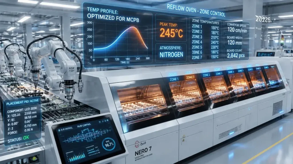
Smart Aluminum PCB SMT Reflow Soldering Line – 2026 Update
This guide walks through the thermal behavior of aluminum PCB boards, the reflow
controls that matter most, a workable 2026 reflow profile, and the DFM data a manufacturer
needs before your first prototype run. Shenzhen Hongda Circuit Technology Co., Ltd. put
this together based on the SMT defect patterns we see most often when a customer’s
Gerber package first lands on our line.
What Is an Aluminum PCB Board and Why Does It Need Special Soldering Care
An aluminum PCB — also called an alu PCB, aluminium PCB (UK spelling), or more
formally a metal core PCB (MCPCB) — replaces the standard FR-4 core with an aluminum
or aluminum-alloy substrate bonded to a thin dielectric layer and copper foil. The
aluminum layer isn’t there to carry signal; it’s there to pull heat away from LEDs, MOSFETs,
and other power components far faster than an epoxy-glass board ever could.
That same conductivity is what makes soldering an aluminum PCB board harder than it
looks. A copper-clad FR-4 board holds heat at the pad long enough for solder to wet
properly. An aluminum-core board acts almost like a heatsink sitting directly under the
joint, so the same reflow settings that work fine on FR-4 routinely produce cold, dull, or
partially wetted joints on aluminum.
Why Aluminum PCB Boards Are Prone to Cold Solder Joints
The Heat-Dissipation Problem Behind Weak Solder Joints
The core issue isn’t that aluminum PCB boards are heat-sensitive — most are rated for
continuous operation well above the temperatures used in reflow. The problem is that heat
is removed from the joint faster than it’s supplied. During reflow or hand soldering, thermal
energy diffuses sideways and downward into the metal core almost as quickly as the iron or
the oven delivers it, so the solder paste never fully reaches its liquidus temperature at the
pad surface. The result is a cold solder joint, sometimes called a weak joint, even though the
top-side reflow indicator on the board looks fine.
Common Defect Symptoms Found During SMT Inspection
Boards affected by this show up in a fairly predictable pattern during IPQC or AOI/X-ray
inspection:
1. Solder joints that look dull, grainy, or under-filled rather than smooth and concave
2. Poor wetting between the pad and component lead, visible as a thin meniscus or bare
metal edge
3. Elevated void rates on X-ray, particularly under QFN and thermal pads
4. Intermittent or unstable function-test results traceable back to a marginal joint rather
than a component failure
Catching these at incoming inspection is far cheaper than catching them after the board is
potted, mounted in a housing, or shipped.
Reflow Soldering vs Hand Soldering for Aluminum PCB Boards
Why Reflow Soldering Is the Standard for Aluminum PCB Board Mass Production
For any real production volume, reflow soldering is the correct process for aluminum PCB
assembly. A properly profiled reflow oven delivers heat uniformly and repeatably across the
whole panel, which is exactly what a fast-dissipating substrate needs — consistent thermal
input rather than a localized heat source fighting against the metal core.
When Hand Soldering Aluminum PCB Boards Still Makes Sense
Hand soldering has a place, but it’s a narrow one: small-batch rework, prototype touch-up,
or repairing a single component on an otherwise good board. When it’s used, temperature,
dwell time, and solder volume all need tighter control than on FR-4 — typically an iron tip
in the 300–350°C range, minimal contact time, and no repeated reheating of the same pad,
which oxidizes the surface and makes the next attempt at wetting even harder.
Critical SMT Reflow Control Points for Aluminum PCB Manufacturer Partners
Pad and Stencil Design for Aluminum PCB Boards
Pad geometry has to follow IPC land-pattern standards and match the component footprint
closely — pads that are oversized or undersized on an aluminum PCB board tend to
produce either starved joints or solder bridging more readily than on FR-4, because there’s
less thermal margin for error. Stencil apertures are typically opened 10–15% larger than the
pad to guarantee adequate paste volume, but on high-thermal-mass boards this needs to be
balanced carefully so components don’t float or tombstone from excess paste.
Solder Paste Selection and Aperture Control
Large thermal pads under heat-generating components deserve special attention at the
stencil stage. Rather than one large paste deposit, splitting the aperture into several smaller
windows reduces the risk of component float and paste-related tombstoning. For boards
with particularly high thermal conductivity, working with your SMT partner to select a
higher-activity, higher-heat-tolerance paste alloy helps maintain wetting even as the core
draws heat away from the joint.
Temperature and Dwell-Time Management
Because aluminum PCB boards dissipate heat so efficiently, the practical fix is a higher
peak temperature and a more deliberate ramp rate than you’d use on standard laminate —
not because the board can’t take the heat, but because the joint needs enough thermal
energy delivered over enough time to reach full wetting before the core carries it away.
Recommended Reflow Profile for Aluminum PCB Board Assembly in 2026
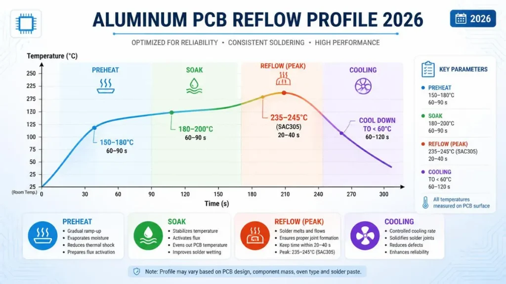
How to Solder Aluminum PCB – Recommended SMT Reflow Profile
The reflow profile below is a practical starting point for a typical aluminum PCB board
using lead-free SAC-alloy paste. It’s a baseline, not a fixed recipe — actual settings still need
to be tuned against board thickness, aluminum vs. aluminum-alloy core type, component
thermal mass, and the specific reflow oven.
| Zone | Temperature | Duration | Purpose |
|---|---|---|---|
| Preheat | 150-180°C | 60-90 s | Slowly drives off solvent in the paste |
| Soak | 180-200°C | 40-60 s | Improves wetting, reduces thermal shock |
| Reflow (peak) | 235-245°C (SAC lead-free) | 20-40 s | Full liquidus wetting at the pad |
| Cooling | ~2-3°C/s ramp down | — | Controlled solidification, prevents joint cracking |
Manufacturing lines running current-generation SMT equipment now lean on a few 2026
era process aids to hold this profile consistently across a full production panel rather than
just a test coupon:
1.Closed-loop, zone-adaptive reflow ovens that adjust each heating zone in real time
against thermocouple feedback from a representative aluminum-core panel, instead
of running a fixed static profile
2. Nitrogen-atmosphere reflow to reduce oxidation at the higher peak temperatures
aluminum boards often require, improving wetting without adding flux load
3. 3D SPI (solder paste inspection) measuring paste height and volume at every
aperture before the panel enters the oven, catching an under-printed thermal pad
before it becomes a cold joint
4. AI-assisted AOI and X-ray void analysis that flags void-rate drift under thermal pads
panel-by-panel rather than sampling a handful of boards per lot
None of this replaces good pad, stencil, and profile design — it just makes the target profile
actually repeatable across a full production run instead of only the engineering sample.
DFM Checklist Before Aluminum PCB Board Production
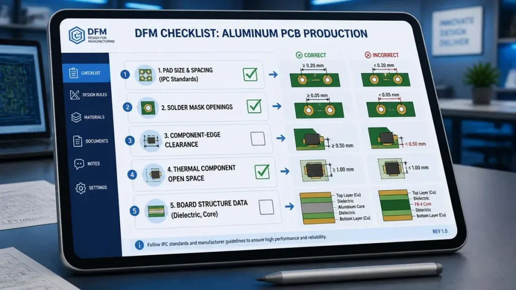
How to Solder Aluminum PCB – Factory DFM Checklist Interface
Design Data an Aluminum PCB Manufacturer Needs at the Prototype Stage
A DFM review before tooling saves far more time than fixing defects after the fact. At
minimum, check:
1.Pad size and spacing against IPC standards for the specific component package
2. Solder mask openings around thermal pads and high-current traces
3 Clearance between components and board edge, and between heat-sensitive parts
and heat sources
4. Adequate open space around high-power devices (power LEDs, MOSFETs) so heat
isn’t trapped locally
To get a useful DFM response back quickly, hand your manufacturer:
- Aluminum PCB board structure data — dielectric thickness, metal-core thickness,
and thermal conductivity of the dielectric layer - Datasheets for the key thermal components and your intended soldering process
- The product’s operating temperature range and expected service life, so the reflow
profile can be optimized around real-world conditions rather than a generic default
How Shenzhen Hongda Circuit Technology Builds Reliability Into Every Aluminum PCB Board
At Shenzhen Hongda Circuit Technology Co., Ltd., aluminum PCB board and aluminum
box PCB orders go through a DFM check before tooling starts, not after the first bad batch
comes back from SMT. Our process pairs laser direct imaging for pad accuracy with 3D SPI
and AOI/X-ray inspection at the reflow stage, so paste volume and void rate on thermal pads
are checked panel-by-panel rather than by spot sample. For customers moving from
prototype to volume, we work directly with your design team on dielectric thickness, metal
core selection, and the reflow profile itself — because on an aluminum PCB, the profile is
part of the design, not an afterthought handled solely on the SMT floor.
Whether you need a standard aluminum PCB manufacturer relationship for LED lighting
boards or a more specialized aluminum box PCB enclosure for a power module, getting the
thermal and soldering strategy right at the quoting stage is what keeps a pilot build from
turning into a rework project.
Frequently Asked Questions From Buyers Sourcing an Aluminum PCB Manufacturer
What should I look for when choosing an aluminum PCB manufacturer?
Beyond price and lead time, check whether the manufacturer runs a DFM review before tooling, what inspection methods they use for solder joint quality (AOI, X-ray void analysis), and whether they can share a reflow profile tailored to your specific board thickness and metal-core type rather than a generic one-size-fits-all setting.
How is an aluminum PCB made, and does that affect soldering results?
An aluminum PCB is built by bonding a copper circuit layer to an aluminum or aluminum-alloy base through a thermally conductive dielectric layer. That construction is exactly why soldering behaves differently than on FR-4 — the base pulls heat away from the joint quickly, so a manufacturer’s process (profile, paste choice, stencil design) has to account for it directly.
Can a standard PCB assembly line handle aluminum PCB boards, or does it need special equipment?
Most SMT lines can run aluminum PCB boards, but consistent quality
depends on process tuning rather than exotic equipment — a reflow oven capable of a higher, well-controlled peak temperature, SPI to verify paste volume at thermal pads, and AOI/X-ray inspection to catch void rate and wetting issues before the board ships.
What’s the difference between an aluminum PCB board and an aluminum box PCB?
An aluminum PCB board is the flat, single-layer metal-core circuit board itself. An aluminum box PCB typically refers to a board fabricated or housed within a metal enclosure structure — often for applications needing both thermal management and mechanical/EMI protection — and usually involves additional fabrication and assembly steps beyond a standard flat MCPCB.
Why do some aluminum PCB boards fail function testing even when they look fine visually?
A cold or partially wetted solder joint can look acceptable to the naked eye while still being electrically marginal or mechanically weak. This is common on aluminum PCB boards because the fast heat dissipation can leave a joint under-wetted without an obvious visual defect — which is why X-ray and AOI inspection at the reflow stage matter more here than on standard FR-4 assemblies.
About Author
David Chen https://www.linkedin.com/in/pcbcoming
David Chen boasts an extensive professional background in PCBA manufacturing, PCBA testing, and PCBA optimization, with specialized expertise in high-precision PCBA fault analysis and rigorous PCBA reliability testing. The author has worked with high-layer-count server PCB fabrication, ultra-low-loss backplane stackups, and thermo-mechanical reliability optimization for AI infrastructure projects involving 112G and 224G PAM4 architectures. Skilled in complex circuit design and cutting-edge advanced PCB manufacturing processes, he delivers solutions that elevate product durability and performance across industrial applications. His technical articles focusing on PCBA manufacturing workflows and testing methodologies are widely cited by industry peers, research institutions, and technical platforms, solidifying his reputation as a recognized technical authority in the global circuit board manufacturing sector.