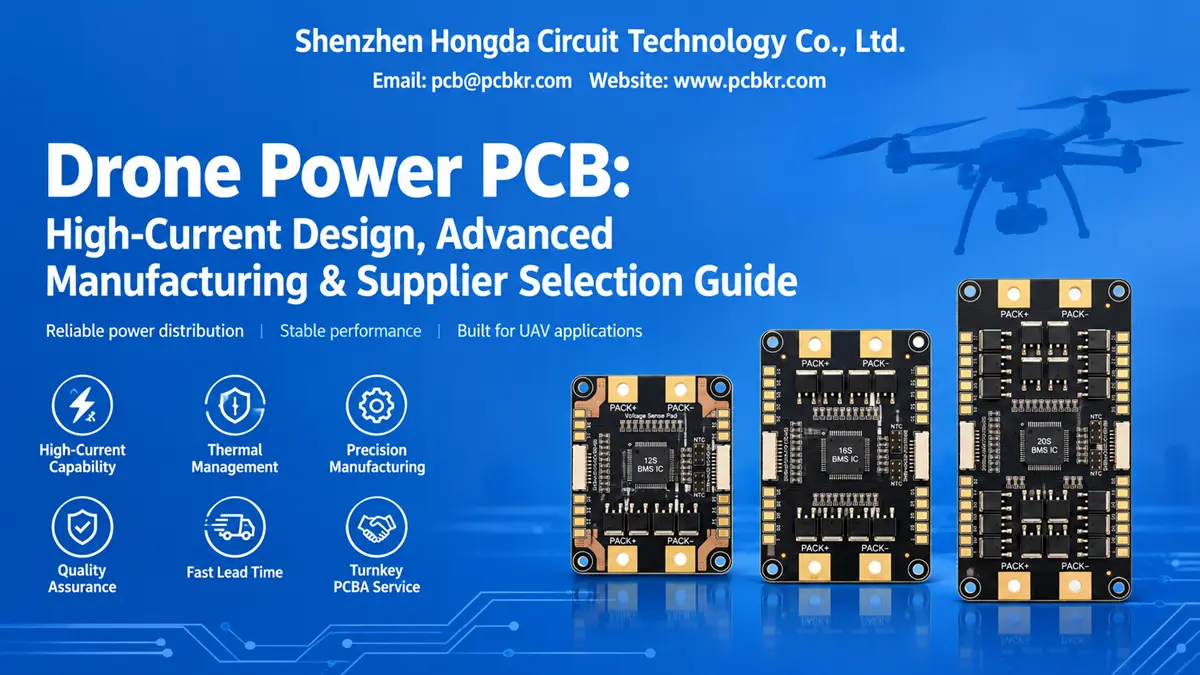
Drone Power PCB: High-Current Design, Advanced Manufacturing & Supplier Selection Guide
A drone power PCB takes battery power and sends it where it needs to go — to the ESCs, the flight controller, and whatever else is flying on that frame. How well it does that comes down to current capacity, voltage drop, heat, connector integrity, and how consistently it comes off the line. For OEMs and procurement teams, picking a PCB and PCBA supplier involves more than comparing copper thickness or unit price.
At Shenzhen Hongda Circuit Technology Co., Ltd. (PCBKR), we run drone power projects through engineering review, manufacturing feasibility, process control, assembly planning, and customer-defined verification. This guide covers what buyers should put in the RFQ, which manufacturing steps actually matter, and how to vet a supplier for both prototypes and production.
1. What Is a Drone Power PCB and How Does It Work?
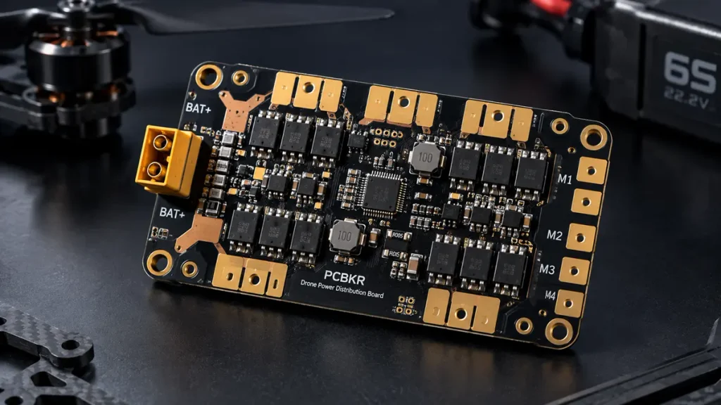
High-Current Drone Power Distribution Board (PDB) Layout Featuring Gold-Plated Pads, Integrated Power MOSFETs, and Heavy Copper Traces by PCBKR.
A drone power PCB is the set of copper traces and planes that carries battery power to the systems aboard a UAV. Depending on the design, it may also handle voltage regulation, current sensing, filtering, and protection.
A typical power-distribution architecture includes:
- Battery input — where the battery pack connects.
- Power distribution paths — routes current to the ESCs and other loads.
- Regulated power rails — supplies for electronics that need specific voltages.
- Monitoring circuits — measure current, voltage, or temperature when required.
- Protection circuitry — defined responses to electrical faults, when it’s part of the design.
- Connectors and terminals — the electrical and mechanical links between the PCB, battery, ESCs, and other assemblies.
What Is the Difference Between a Drone Power PCB, PDB, ESC, and Flight Controller?
These terms describe different jobs, even though some commercial products bundle several into one board.
| Board or assembly | Primary function | Key engineering concern |
|---|---|---|
| Drone Power PCB / PDB | Distributes electrical power | Current capacity, resistance, heat, and connections |
| ESC | Controls electrical power delivered to a motor | Switching losses, current, thermal management, motor control |
| Flight controller PCB | Processes flight-control inputs and sensor data | Signal integrity, noise immunity, stable power |
| Power management PCB | Regulates, monitors, or protects power | Conversion efficiency, voltage stability, protection behavior |
For procurement, the distinction matters because a passive distribution board doesn’t have the same component, assembly, or testing needs as a board carrying high-current MOSFETs, switching regulators, or integrated ESC functions.
2. Which Drone Power PCB Specifications Should Buyers Confirm Before Requesting a Quote?
Pin down the electrical load profile, board construction, mechanical interfaces, environmental conditions, and acceptance criteria before asking for a quote. If any of these are vague, supplier quotes are hard to compare, and you’ll pay for it in engineering changes after the first prototype.
Which Electrical Parameters Matter for a Drone Power Distribution PCB?
The RFQ should state:
- Battery chemistry, cell count, and operating voltage range.
- Continuous current for each output and for the supply as a whole.
- Peak current, peak duration, and load duty cycle.
- Required regulated outputs and their current ratings.
- Maximum permitted voltage drop.
- Acceptable temperature rise and operating ambient temperature.
- Connector types, terminal ratings, and wire-gauge requirements.
- Protection functions and monitoring interfaces.
- Expected operating life and environmental conditions.
A “4S” or “6S” battery is a useful starting point, but cell count alone doesn’t define the real voltage range or current need. The supplier needs the actual battery specs and the loads on each power path.
How Should Buyers Specify Drone Power PCB Copper Thickness and Layer Count?
Copper weight and layer count follow from current distribution, available routing area, resistance, thermal limits, board size, and cost.
Possible constructions:
- Standard copper for compact or moderate-current designs.
- Heavier copper where you need more conductor cross-section.
- Multilayer power planes when routing density and current justify the extra layers.
- Dedicated thermal structures or busbars when standard PCB copper can’t hit the electrical and mechanical targets economically.
Treat copper weight as a starting figure, not a standalone current rating. The finished trace geometry, plated thickness, vias, pads, connectors, and cooling all shape the real number.
What Mechanical Information Belongs in a Drone Power PCB RFQ?
Include the board outline, thickness, mounting-hole positions, connector orientation, component-height limits, enclosure clearances, and expected mechanical loads. For industrial, agricultural, and heavy-lift UAVs, also flag vibration, cable restraint, environmental temperature, moisture, and any ingress-protection requirement for the full assembly.
3. How Do Copper Thickness and Trace Geometry Affect High-Current Drone Power PCB Performance?
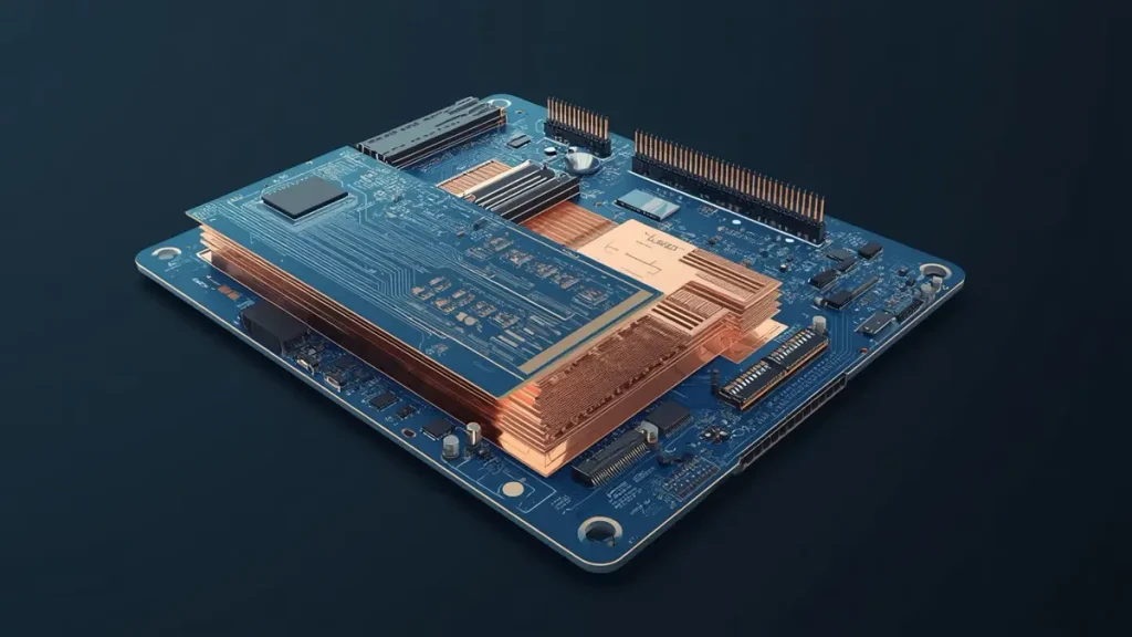
3D Cross-Sectional View of Heavy Copper Drone Power PCB Architecture Showing Thick Internal Copper Planes and Multi-Layer Stackup.
High-current performance comes down to resistance and heat along the entire current path — not just the nominal copper weight.
That path may include the battery connector, trace, pad, plated via, internal plane, component terminal, and return conductor. Any one of these can become a local bottleneck.
How Can Engineers Calculate Drone Power PCB Voltage Drop and Power Loss?
For a first engineering pass:
- Voltage drop: V = I × R
- Resistive power loss: P = I² × R
- Conductor resistance: R = ρ × L / A
I is current, R is resistance, ρ is resistivity, L is length, and A is cross-sectional area.
Take a path with 1 milliohm total resistance carrying 60 A:
- Voltage drop = 60 × 0.001 = 0.06 V.
- Resistive power loss = 60² × 0.001 = 3.6 W.
That’s why milliohm-level resistance matters in high-current circuits. This is a worked example, not a measured PCBKR result. Real numbers depend on temperature, trace geometry, connector resistance, solder joints, and the whole path.
When Should a Drone Power PCB Use Heavy Copper?
Heavy copper is worth a look when current, voltage drop, thermal performance, or routing limits can’t be met economically with a conventional construction.
The tradeoff: heavier copper is harder to etch, tightens minimum feature spacing, changes finished trace geometry, and complicates fine-pitch routing. Have the fab review feasibility before you release the design. Where high-current traces and fine-pitch parts sit on the same board, make sure the proposed layer stack and process can handle both.
4. How Can Engineers Prevent Drone Power PCB Overheating and Voltage Drop?
Look at current distribution, connection resistance, component losses, thermal paths, and operating conditions together. Adding copper doesn’t fix every heat problem.
Why Do Drone Power PCB Connectors and Solder Joints Become Hot?
Local heating usually traces back to high contact resistance, too little contact area, poor solder wetting, an undersized terminal, or mechanical movement that breaks the joint.
The review should cover connector current ratings under the actual installation conditions, pad geometry, solder-joint requirements, wire attachment, and strain relief. For high-current interfaces, ask for appropriate assembly inspection and, where justified, resistance or temperature readings under a defined load.
How Should Thermal Vias and Copper Planes Be Evaluated?
Thermal vias move heat between layers; larger copper areas spread it across the board. How well they work depends on via geometry, plating, plane connectivity, component placement, and whether heat can actually leave the assembly.
The analysis should consider the whole installation — enclosure airflow, nearby heat sources, mounting hardware, ambient temperature. A thermal simulation can point at likely hotspots, but you need physical testing under representative conditions to confirm the critical assumptions.
5. Which Advanced PCB Manufacturing Technologies Matter for Drone Power PCB Production?
The technology that matters is the one that controls a specific risk in your design. Heavy-copper process control, precision imaging, laser drilling, controlled lamination, and automated inspection each tackle a different problem.
Shenzhen Hongda Circuit Technology Co., Ltd. uses SCREEN Ledia laser direct imaging (LDI), Mitsubishi UV/CO₂ laser drilling, LAUFFER lamination, and automated inspection and electrical verification for applicable constructions. Whether any of these matter for a given drone power PCB depends on the design.
How Does SCREEN Ledia LDI Help Manufacture Drone Power PCBs?
LDI transfers circuit patterns without conventional phototool imaging. It can improve pattern registration and consistency where you have fine features, dense routing, or tight alignment tolerances.
For a drone power PCB, good imaging matters when power conductors share a board with fine-pitch control electronics, sensing circuits, and compact footprints. LDI doesn’t set current capacity or guarantee thermal performance — those come from finished geometry, copper construction, electrical design, and validation.
When Does Mitsubishi UV/CO₂ Laser Drilling Matter for a Drone Power PCB?
Laser drilling makes microvias and other interconnects in HDI constructions where mechanical drilling won’t work.
It’s useful when the design combines compact dimensions, dense routing, and multilayer connections. The via diameter, capture-pad geometry, copper plating, and interconnect reliability all have to be checked against the stack-up. A simple distribution board often doesn’t need HDI microvias. Pick the manufacturing route from the actual electrical and mechanical requirements, not from technology complexity for its own sake.
How Does LAUFFER Lamination Support Multilayer Drone Power PCBs?
Controlled lamination keeps layer bonding, stack-up integrity, and dimensional stability in check during multilayer fabrication.
That matters when a board needs multiple copper planes, dense interconnects, or demanding thickness and registration tolerances. Confirm the stack-up, material system, finished thickness, copper distribution, and lamination process before production.
When Are mSAP and Fine-Line PCB Processes Relevant to Drone Power PCB Manufacturing?
The modified semi-additive process (mSAP) is really for fine-line structures and high-density interconnects. It holds geometries that conventional subtractive etching struggles to maintain.
mSAP can be a fit for a compact, integrated assembly that packs dense control electronics with tight routing. It’s not automatically right for a high-current distribution board, where conductor cross-section, current paths, thermal behavior, and cost usually dominate.
PCBKR’s published capabilities include mSAP, HDI, precision laser processing, and fine-line. Match the process to the actual board design and production spec.
How Do AOI, X-Ray, and Electrical Testing Improve Drone Power PCB Quality?
Different methods catch different defects:
- AOI: checks accessible surface features, including visible circuit-pattern defects.
- X-ray: looks at hidden structures and solder joints, especially under parts like BGAs.
- Electrical testing: checks continuity and isolation against the test requirements.
- Microsection analysis: assesses internal copper, plating, and layer construction when required.
- Functional or load testing: verifies specified electrical behavior under defined conditions.
These are complementary. AOI won’t establish current capacity, and a continuity pass alone doesn’t prove thermal reliability. Match the inspection plan to the actual design risks and acceptance criteria.
6. How Should a Drone Power PCB Manufacturer Control Manufacturing Risks?
Reliable production needs a controlled process from engineering review through fabrication, assembly, inspection, and release. The procurement question is whether the supplier can show, repeatably, that the finished board meets the agreed requirements.
What Are the Main Drone Power PCB Manufacturing Pain Points?
- Copper geometry and plating variation. Heavy-copper circuits need careful etching and plating control. Review finished copper thickness, conductor dimensions, minimum spacing, and process tolerances.
- Layer registration and stack-up variation. Misalignment or dimensional drift hurts interlayer connections and finished geometry, especially in multilayer or HDI designs.
- Thermal and electrical bottlenecks. A board can pass continuity testing and still show excessive voltage drop or localized heating under load. Design review and load validation catch these.
- Assembly defects around high-current components. Large terminals, connectors, and heavy parts may need specific soldering, mechanical support, and inspection controls. Match the assembly process to the package and connection design.
- Uncontrolled engineering revisions. Changes to copper geometry, components, stack-up, or assembly drawings can invalidate earlier approvals. Revision control has to cover fabrication data, BOMs, assembly files, and test procedures.
How Should Drone Power PCB Prototype Validation Be Organized?
A practical plan looks something like this:
- Review the released design data and confirm manufacturing feasibility.
- Verify stack-up, copper construction, dimensions, and critical features.
- Inspect the fabricated board and run the agreed electrical tests.
- Assemble per the approved BOM and assembly documentation.
- Check polarity, solder joints, connector installation, and other critical features.
- Do a controlled power-up, voltage measurements, and the agreed load tests.
- Measure temperature rise, voltage drop, and protection behavior against your limits.
- Document deviations and approve the revision before production release.
The drone OEM still owns system-level integration and flight validation. PCB and PCBA acceptance testing isn’t a substitute for full UAV qualification.
7. How Can Buyers Evaluate a Drone Power PCB Supplier Before Placing an Order?
A qualified supplier should show relevant manufacturing capability, engineering support, inspection coverage, traceability, and a clear quotation scope. Compare evidence, not broad claims about quality or fancy equipment.
Which Supplier Capabilities Should Buyers Verify?
| Evaluation area | Questions to ask | Evidence to request |
|---|---|---|
| PCB fabrication | Can the supplier meet the specified copper, stack-up, and geometry? | Capability review and construction confirmation |
| Engineering support | Are design risks identified before production? | DFM comments and documented clarifications |
| PCBA services | Can the supplier handle the required components and soldering processes? | Assembly capability review and process plan |
| Inspection | Are critical defects covered by suitable methods? | Inspection plan and applicable test records |
| Electrical validation | Can the specified load and electrical tests be performed? | Test procedure, conditions, and acceptance limits |
| Traceability | Can material and revision changes be controlled? | Lot records, revision history, change-control procedure |
| Production planning | Can prototypes and production orders be quoted with clear assumptions? | Lead-time basis, quantity breaks, quotation scope |
Can One Manufacturer Supply Both Drone Power PCB Fabrication and PCBA Assembly?
A one-stop supplier can coordinate bare-board fabrication, component sourcing, assembly, inspection, and agreed electrical testing — if those services fall inside its qualified scope.
That can cut handoff delays and simplify who owns manufacturing issues. Still, confirm which processes get subcontracted, how component substitutions are approved, and who drives corrective action when a defect shows up.
Shenzhen Hongda Circuit Technology Co., Ltd. supports PCB manufacturing and PCBA-related projects. Confirm the exact scope, material availability, assembly requirements, and test coverage for each drone power RFQ.
8. What Determines Drone Power PCB Manufacturing Cost and Lead Time?
Cost and lead time follow the whole construction and scope, not just board dimensions.
Cost drivers include:
- Board size, layer count, and material selection.
- Copper weight and finished conductor requirements.
- Minimum trace width and spacing.
- Via structure and drilling requirements.
- Surface finish and dimensional tolerances.
- Component sourcing and BOM availability.
- SMT, through-hole, or mixed assembly.
- Inspection, electrical testing, and custom fixtures.
- Order quantity, panel utilization, and production yield.
- Engineering changes and qualification requirements.
A low bare-board price isn’t a low total procurement cost if it brings extra inspection, rework, outsourced assembly, or repeated revisions. To compare fairly, get quotes on the same released design files, quantities, quality requirements, test scope, packaging, and delivery terms.
9. What Should Buyers Include in a Drone Power PCB RFQ?
A complete RFQ lets the manufacturer judge feasibility, flag missing information, and quote the right scope.
PCB fabrication data
- Gerber or ODB++ files.
- NC drill files and board outline.
- Stack-up and finished board thickness.
- Copper weight and critical conductor requirements.
- Surface finish, solder mask, and applicable tolerances.
- Quantity and target delivery date.
Assembly data
- BOM with manufacturer part numbers.
- Pick-and-place file.
- Assembly drawings and polarity information.
- Approved alternatives or restrictions on component substitutions.
- Required SMT and through-hole processes.
Electrical and environmental requirements
- Battery voltage range.
- Continuous and peak current profiles.
- Required voltage-drop and temperature-rise limits.
- Regulated output requirements.
- Operating temperature and environmental conditions.
- Required protection, monitoring, and load-test functions.
Quality and commercial requirements
- Inspection and acceptance criteria.
- Required traceability and documentation.
- Prototype, pilot, and production quantities.
- Packaging and delivery requirements.
- Applicable compliance or certification requirements.
If something isn’t final, label it an open engineering item rather than letting the supplier assume.
10. Why Consider Shenzhen Hongda Circuit Technology Co., Ltd. for Drone Power PCB Projects?
Start with technical fit, not a generic “we can build anything” claim.
Shenzhen Hongda Circuit Technology Co., Ltd. (PCBKR) offers PCB manufacturing and PCBA-related services, with laser direct imaging, laser drilling, controlled lamination, HDI and fine-line processes, and inspection and electrical verification for applicable constructions.
For drone power projects, our engineering review focuses on:
- Whether the specified copper construction and current paths are feasible.
- Whether the layer stack-up and interconnect structure make sense.
- Manufacturing risks in trace geometry, drilling, plating, and registration.
- Assembly requirements for high-current terminals and electronic components.
- Appropriate inspection and electrical verification for the agreed design.
- Production documentation, revision control, and quotation scope.
Advanced equipment only helps when it solves a real design constraint. Sometimes the right answer is a conventional power PCB with a carefully engineered copper structure; sometimes it’s a denser multilayer assembly. The choice should follow the project’s electrical performance, mechanical needs, risk tolerance, and cost target.
To discuss a project, visit https://www.pcbkr.com/ or email pcb@pcbkr.com.
Request a Drone Power PCB Manufacturing and PCBA Quote
Whether you’re building an FPV drone, industrial UAV, agricultural drone, or heavy-lift platform, send your board files and electrical requirements so the construction and manufacturing scope can be reviewed before production.
Send your Gerber or ODB++ files, BOM, battery voltage range, continuous and peak current profile, copper requirements, target quantities, and testing criteria to:
Shenzhen Hongda Circuit Technology Co., Ltd. Email: pcb@pcbkr.com
Request a quotation for your drone power PCB prototype or production project.
Frequently Asked Questions About Choosing a Drone Power PCB Supplier
How do I choose a reliable drone power PCB manufacturer?
Look at the supplier’s copper and stack-up capability, engineering review process, inspection methods, electrical testing scope, material traceability, revision control, and ability to support your volumes. Ask for evidence tied to your design, not general quality claims.
What files should I send to a drone power PCB supplier for a quotation?
For bare-board fabrication: Gerber or ODB++ files, drill data, stack-up, copper requirements, board dimensions, quantity, and delivery requirements. For PCBA, add the BOM, pick-and-place file, assembly drawings, component restrictions, and required inspection and test criteria.
Can a drone power PCB supplier manufacture both the PCB and assembled board?
Yes, if the supplier has the fabrication and assembly capabilities. Confirm the actual scope, component sourcing arrangements, subcontracting policy, and who owns defect resolution before placing the order.
How can I compare drone power PCB supplier quotations fairly?
Compare quotations using the same design revision, board dimensions, layer stack-up, finished copper requirements, materials, surface finish, assembly scope, inspection plan, electrical test criteria, order quantity, and delivery terms. Ask each supplier to identify exclusions, component substitutions, subcontracted processes, and any assumptions affecting price or lead time. Evaluate total procurement cost and technical compliance rather than comparing bare-board unit prices alone.
What quality tests should I request before approving a drone power PCB supplier?
Depending on the design, request appropriate visual or AOI inspection, continuity and isolation testing, relevant solder-joint inspection, and documented voltage-drop, load, or thermal testing. Define conditions and acceptance limits up front. No single inspection method proves electrical, thermal, and flight reliability at once.
About the author
David Chen (LinkedIn Profile)
David Chen is a Senior RF/PCB Process Engineer at Shenzhen Hongda Circuit Technology Co., Ltd., with over 12 years of experience in high-frequency PCB fabrication, impedance-controlled stack-up design, and Rogers/PTFE laminate processing. He also boasts an extensive professional background in PCBA manufacturing, PCBA testing, and PCBA optimization, with specialized expertise in high-precision PCBA fault analysis and rigorous PCBA reliability testing. The author has worked with high-layer-count server PCB fabrication, ultra-low-loss backplane stackups, and thermo-mechanical reliability optimization for AI infrastructure projects involving 112G and 224G PAM4 architectures. Skilled in complex circuit design and cutting-edge advanced PCB manufacturing processes, he delivers solutions that elevate product durability and performance across industrial applications. His technical articles focusing on PCBA manufacturing workflows and testing methodologies are widely cited by industry peers and technical platforms, and have gained attention and recognition from industry colleagues.
This guide is meant to help engineering and procurement teams define requirements, evaluate manufacturing risks, and make evidence-based supplier decisions for custom drone power PCB projects.