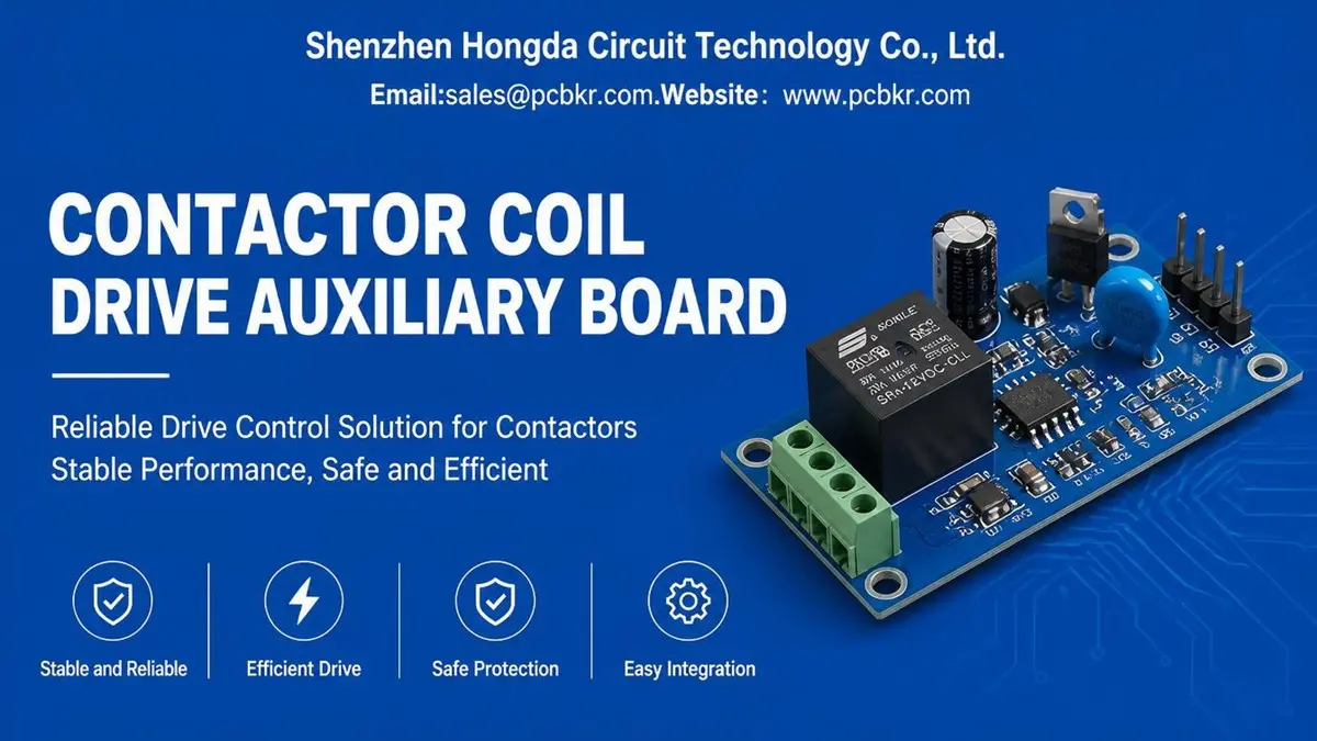
Contactor Coil Drive Auxiliary Board for Industrial Control Systems
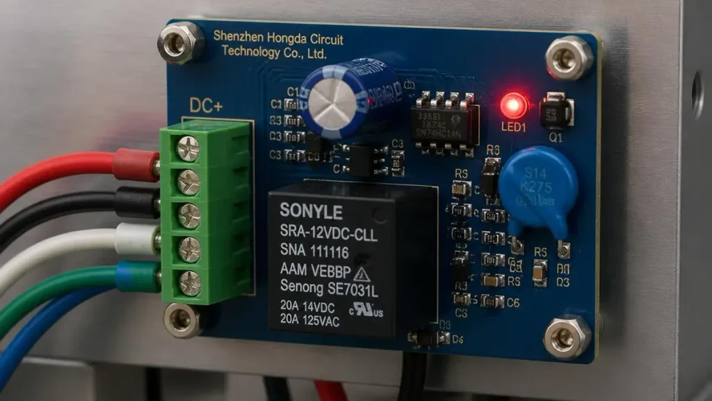
PCB Material:FR-4 / High-Tg FR-4
Layer Count:2–6 Layers
Board Thickness:1.0–2.0 mm
Copper Thickness:1–3 oz
Minimum Trace Width / Spacing:0.15 / 0.15 mm
Minimum Hole Diameter:0.20 mm
A Contactor Coil Drive Auxiliary Board provides the electronic interface between a control system and a contactor coil. It manages coil energization, switching, transient suppression and, where required, pull-in and hold-current control. For industrial OEM equipment, the board must be designed around the contactor’s electrical characteristics, switching frequency, operating environment and required release time. Reliable performance also depends on PCB layout, component selection, thermal management, assembly quality and functional testing.
For equipment manufacturers, the board is more than a simple switching circuit. An inadequately designed coil driver can cause MOSFET failure, excessive coil heating, delayed contactor release, electrical interference or damage to the upstream PLC and control electronics. A suitable PCB and PCBA manufacturing partner must therefore understand both the electrical requirements and the manufacturing factors that influence long-term reliability.
1. Contactor Coil Drive Auxiliary Board Overview
A Contactor Coil Drive Auxiliary Board is an electronic circuit board used to control the energization and de-energization of an electromagnetic contactor coil. It receives a control signal from a PLC, embedded controller, power management unit or other industrial control system and switches the required current to operate the contactor.
Depending on the equipment architecture, the board may integrate several functions:
- Coil switching through MOSFETs, transistors or relay-based drivers.
- Electrical isolation between control and power-side circuits.
- Flyback voltage or transient suppression.
- Pull-in and hold-current management for supported DC contactors.
- Coil current monitoring and fault detection.
- Auxiliary contact status feedback.
- Interface protection against electrical noise and control-line disturbances.
The actual configuration depends on the contactor model, coil voltage, coil current, control architecture and system safety requirements. Not every auxiliary board requires all these functions.
Typical Industrial Applications
Contactor coil driver circuits are used in equipment where an electrical control signal must operate a contactor reliably.
| Application | Typical board function |
|---|---|
| Industrial automation equipment | PLC-controlled contactor switching |
| Motor control cabinets | Motor power circuit activation and isolation |
| EV charging equipment | Contactor coil control and switching coordination |
| Battery energy storage systems | High-voltage DC contactor control |
| Power distribution equipment | Remote switching and control interlocking |
| Industrial power supplies | Controlled connection and disconnection of power circuits |
| HVAC and industrial machinery | Compressor, heater and motor contactor control |
In high-voltage DC applications, the coil driver may also be integrated with an economizer or diagnostic circuit. These functions must be designed according to the contactor manufacturer’s specifications rather than treated as universal requirements.
2. Contactor Coil Driver Circuit Architecture
A typical Contactor Coil Drive Auxiliary Board contains a control input, switching stage, coil connection, protection network and optional feedback circuit.
2.1 Control Signal Input
The control input receives the switching command from the host system. Common interfaces include digital control signals from PLC outputs, microcontrollers or dedicated industrial control modules.
The input circuit may include:
- Signal conditioning.
- Input current limiting.
- Optocoupler or other isolation components.
- Transient protection.
- Logic-level compatibility circuits.
Input voltage and isolation requirements must be determined from the host controller and the applicable system design. A 24 VDC control interface, for example, should not be assumed to be compatible with every contactor coil or driver architecture.
2.2 Coil Switching Stage
The switching stage controls the current supplied to the contactor coil.
For DC contactors, common switching components include:
- N-channel or P-channel MOSFETs.
- Bipolar junction transistors.
- Dedicated high-side or low-side driver ICs.
- Gate resistors and gate-protection components.
MOSFET-based switching is common in electronically controlled DC coil applications because it supports efficient switching and can be integrated with current monitoring or economizer functions.
Component selection must account for the coil’s pull-in current, steady-state current, switching transients, supply variation and operating temperature. The MOSFET voltage rating must also provide sufficient margin for the transient voltage produced when the coil is switched off.
2.3 Coil Current Path
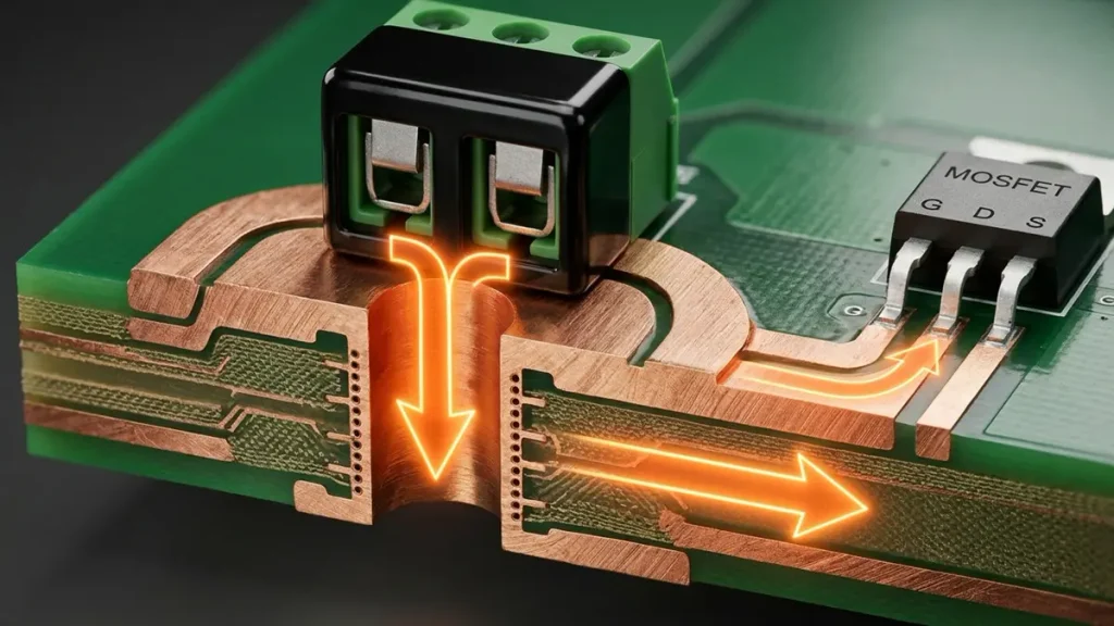
Heavy Copper PCB Cross Section Showing Coil Current Path and Via Design
The coil current path carries the current required to energize the contactor.Its PCB copper width, copper thickness, component terminals and connector ratings must be designed around the actual current profile.
The design should distinguish between:
- Initial pull-in current.
- Steady-state holding current.
- Transient current during switching.
- Abnormal current during fault conditions.
A board designed only around the nominal holding current may be inadequate if the coil draws a significantly higher current during pull-in.
2.4 Auxiliary Feedback and Monitoring
Some designs include feedback signals to report contactor status or driver operating conditions to the main controller.
Possible functions include:
- Auxiliary contact input monitoring.
- Coil current measurement.
- Driver overcurrent detection.
- Open-circuit or abnormal coil detection.
- Switching command and status comparison.
Auxiliary contact feedback is not the same as direct measurement of the main power contacts. The sensing architecture must be defined according to the contactor’s available auxiliary contacts and the system’s diagnostic requirements.
3. Coil Transient Suppression and Switching Reliability
Transient suppression is one of the most important design considerations in a Contactor Coil Drive Auxiliary Board.
A contactor coil is an inductive load. When the driver interrupts coil current, the collapsing magnetic field produces a voltage transient. Without suitable suppression, this transient can exceed the voltage tolerance of the MOSFET, transistor, driver IC or nearby control electronics.
It can also introduce electrical noise into PLC inputs, communication interfaces and other sensitive circuits.
3.1 Common Coil Suppression Methods
The suppression method must match the coil type and the required contactor release characteristics.
| Suppression method | Typical application | Main design consideration |
|---|---|---|
| Flyback diode | DC coil | Simple suppression, but may increase release time |
| TVS diode | DC coil and selected switching circuits | Clamp voltage, pulse energy and component rating |
| Zener-based clamp | DC coil driver | Balances transient voltage and current decay |
| MOV | AC or suitable transient-protection applications | Voltage rating, energy capability and aging |
| RC snubber | AC coil and selected switching circuits | Resistance, capacitance and dissipation |
| Integrated suppression module | Compatible contactor assemblies | Verify the actual built-in protection configuration |
An ordinary flyback diode must not be used across an AC coil. AC and DC coils require different suppression approaches.
3.2 Suppression Voltage and Contactor Release Time
A conventional flyback diode limits the voltage generated by a DC coil when the switching device turns off. However, the lower clamp voltage can cause the coil current to decay more slowly.
This may extend the contactor’s mechanical release time.
A TVS diode or Zener-based clamp can permit a higher controlled voltage during turn-off. This can accelerate current decay while keeping the switching device within its allowable voltage limits.
The correct suppression network must balance three requirements:
- Protect the MOSFET or driver from excessive voltage.
- Maintain the required contactor release time.
- Keep transient energy and thermal stress within component ratings.
The suppression design should be verified against the contactor datasheet and the switching device’s voltage and energy limits. The actual release time must be measured under representative operating conditions.
3.3 PCB Layout for Transient Control
The physical layout of the suppression circuit affects its performance.
Important layout considerations include:
- Place the suppression component close to the coil connection or the relevant switching current loop.
- Minimize the high-current switching loop area.
- Keep sensitive control signals away from high-current switching paths.
- Provide appropriate clearance between different voltage domains.
- Use suitable return paths to reduce unwanted coupling.
- Avoid unnecessary routing length between the switching device and its protection network.
The best suppression topology can still perform poorly if the PCB layout introduces excessive parasitic inductance or couples switching noise into sensitive control circuits.
4. Pull-In, Hold-Current and Coil Economizer Functions
Some DC contactors require a relatively high initial current to pull the armature into position. After the contactor has operated, a lower holding current may be sufficient to maintain the magnetic force.
A coil economizer uses this difference to reduce continuous coil power consumption and heat generation.
4.1 Pull-In and Hold-Current Control
A typical economizer control sequence includes:
- The controller receives a contactor activation command.
- The driver supplies the required pull-in current.
- The circuit transitions to a lower holding-current condition.
- The driver maintains the contactor in its energized state.
- When the command is removed, the driver de-energizes the coil and manages the resulting transient.
The pull-in interval, holding current and transition conditions must follow the contactor manufacturer’s requirements. A fixed timing value should not be applied to every contactor.
4.2 PWM-Based Economizer Design
A PWM-based economizer controls the average coil current by switching the drive stage at a selected frequency and duty cycle.
The design must consider:
- Coil inductance and resistance.
- Required pull-in current.
- Minimum holding current.
- PWM frequency.
- MOSFET switching losses.
- Current ripple.
- Thermal dissipation.
- Audible noise and electromagnetic interference.
- Fault response if the economizer fails.
An unsuitable PWM frequency or holding-current setting can cause unstable operation, excessive heating or unintended contactor release.
4.3 Economizer Fault Monitoring
For applications that require higher reliability, the driver may monitor coil current or operating status to identify abnormal conditions.
Potential diagnostic functions include:
- Failure to reach the expected pull-in current.
- Abnormal holding current.
- Driver overcurrent.
- Open-circuit coil detection.
- Economizer switching failure.
- Unexpected status feedback.
These functions should be defined at the system level. The auxiliary board’s diagnostic output must be compatible with the main controller’s fault-handling strategy.
5. PCB Design Requirements for Contactor Coil Driver Reliability
A Contactor Coil Drive Auxiliary Board must support the electrical, thermal and environmental requirements of the equipment in which it operates.
The PCB design should be reviewed as a complete electrical and manufacturing system rather than as an isolated schematic.
5.1 Current Capacity and Copper Design
Copper thickness and trace geometry must be selected according to the current profile, allowable temperature rise, copper characteristics and PCB construction.
The design review should include:
- Maximum pull-in current.
- Continuous holding current.
- Switching frequency.
- Copper thickness.
- Trace width and length.
- Connector and terminal ratings.
- Localized heating around MOSFETs and power components.
For boards with high current density, thermal simulation or prototype temperature measurement may be appropriate.
5.2 Insulation and Electrical Clearance
Industrial contactor systems may contain different voltage domains on the same PCB.
The design should define:
- Working voltage.
- Transient overvoltage.
- Required insulation level.
- Clearance and creepage distances.
- Pollution degree.
- Material group and operating environment.
- Applicable safety and product standards.
Clearance and creepage requirements cannot be established from board voltage alone. They depend on the equipment standard, insulation category, material properties and installation conditions.
5.3 Thermal Management
MOSFETs, current-sensing resistors, suppression devices and other power components may generate localized heat.
Thermal design considerations include:
- Component power dissipation.
- Copper area and thermal spreading.
- Thermal vias where appropriate.
- Component spacing.
- Enclosure temperature.
- Airflow and mounting orientation.
- Maximum ambient temperature.
- Expected operating duty cycle.
Thermal verification should use the actual component configuration and representative operating conditions. A nominal PCB copper specification by itself does not prove that the assembled board will meet its temperature limits.
5.4 Mechanical and Environmental Reliability
Industrial control boards may operate in environments with vibration, dust, humidity and temperature variation.
The design should consider:
- Connector retention.
- Terminal mechanical strength.
- Component anchoring.
- Board mounting points.
- Coating requirements, where applicable.
- Surface contamination control.
- Environmental testing requirements.
For equipment exposed to repeated vibration or mechanical shock, connector and component selection should be reviewed alongside PCB mounting and assembly design.
6. PCB Materials and Manufacturing Technologies
The reliability of a Contactor Coil Drive Auxiliary Board depends not only on circuit design but also on the PCB material, copper structure, drilling, lamination, pattern formation and assembly process.
The appropriate manufacturing route depends on the board’s layer count, current requirements, insulation design, operating temperature and mechanical constraints.
6.1 PCB Material Selection
FR-4 is commonly used for industrial control boards. High-Tg FR-4 may be considered when the operating environment, thermal requirements or assembly process demands greater thermal performance.
| Material option | Typical consideration |
|---|---|
| Standard FR-4 | General industrial control applications |
| High-Tg FR-4 | Higher thermal requirements and demanding assembly conditions |
| High-CTI material | Applications with specific insulation and tracking requirements |
| Specialized laminate | Applications with unusual thermal, electrical or environmental requirements |
Material selection must be based on the equipment’s operating conditions and applicable electrical safety requirements. A higher Tg value alone does not establish the insulation performance of a PCB.
6.2 Copper Thickness and Circuit Pattern Formation
The copper thickness should be selected according to current capacity, thermal performance and circuit geometry.
Heavy copper may be appropriate for boards carrying higher current, but it can affect etching compensation, trace definition and manufacturing tolerances.
For dense control circuits, the manufacturing process must also maintain the required trace width and spacing around switching, sensing and control sections.
6.3 Multilayer PCB Construction
A multilayer design may be used when the board requires more complex signal routing, power distribution, isolation zones or compact packaging.
The stack-up should account for:
- Layer allocation.
- Power and ground routing.
- Dielectric thickness.
- Copper distribution.
- Electrical clearance.
- Thermal spreading.
- Mechanical stability.
The layer count should be determined by the actual circuit and packaging requirements. A higher layer count is not automatically necessary for every contactor coil driver.
6.4 Drilling, Lamination and Registration
For multilayer PCBs, drilling accuracy, lamination control and layer-to-layer registration affect electrical connectivity and structural reliability.
Manufacturing controls may include:
- Controlled drilling and hole-wall quality.
- Lamination process control.
- Layer registration inspection.
- Plated-through-hole integrity.
- Copper thickness verification.
- Electrical continuity testing.
These controls are particularly relevant when the board uses multiple power and control layers or requires tighter routing constraints.
6.5 PCBKR Manufacturing Process Considerations
Shenzhen Hongda Circuit Technology Co., Ltd. provides PCB fabrication and PCBA manufacturing services for industrial and electronic equipment applications.
Relevant manufacturing technologies and inspection resources include:
- SCREEN Ledia LDI imaging equipment for controlled circuit pattern formation.
- LAUFFER vacuum lamination equipment for multilayer PCB construction.
- Mitsubishi UV/CO₂ laser drilling processes for microvia applications.
- 3D AOI inspection for assembly defect detection.
- X-ray inspection for suitable hidden solder joints and internal assembly features.
- Four-wire Kelvin and flying-probe electrical testing.
- VNA measurement capability for applications requiring high-frequency electrical verification.
These technologies support different manufacturing requirements and are not all necessary for a conventional contactor coil driver board. The manufacturing process should be selected according to the released Gerber or ODB++ data, stack-up, component package, current requirements and inspection plan.
7. PCBA Assembly and Functional Testing
PCB fabrication verifies the bare-board structure. PCBA assembly and functional testing verify whether the assembled board performs according to the electrical and mechanical requirements.
A suitable quality plan should cover incoming materials, component placement, soldering, inspection and application-specific functional verification.
7.1 SMT and THT Assembly
Contactor coil driver boards may use a combination of surface-mount and through-hole components.
Typical assembly requirements include:
- MOSFET and driver IC placement.
- Resistor and capacitor assembly.
- TVS, diode or suppression component installation.
- Connector and terminal block soldering.
- Mixed SMT and THT assembly.
- Polarity and orientation verification.
Power components and connectors require particular attention because poor solder joints or inadequate mechanical support can affect current handling and long-term reliability.
7.2 Assembly Inspection
Inspection methods should be selected according to component type and package structure.
| Inspection method | Main purpose |
|---|---|
| 3D AOI | Detect visible component placement and soldering defects |
| X-ray inspection | Inspect suitable hidden solder joints and internal connections |
| Visual inspection | Check polarity, orientation, workmanship and mechanical assembly |
| Electrical testing | Verify continuity and detect shorts or opens |
| Functional testing | Verify operation against defined electrical requirements |
AOI and X-ray inspection provide different types of evidence. Neither should be presented as a substitute for a complete functional test.
7.3 Functional Test Requirements
A functional test plan should be developed from the approved schematic, test specification and contactor datasheet.
Possible test items include:
- Control input response.
- Coil output voltage.
- Pull-in current profile.
- Holding current.
- Switching operation.
- Turn-off transient voltage.
- Contactor release time.
- Overcurrent response.
- Auxiliary feedback signal.
- Abnormal input and fault response.
For PWM economizer designs, the test plan may also include PWM frequency, duty cycle, current ripple and thermal behavior.
Test limits must be defined by the customer or approved engineering specification. A generic continuity test cannot demonstrate correct coil operation or release timing.
8. Contactor Coil Drive Auxiliary Board Manufacturer Selection
Selecting a PCB and PCBA manufacturer requires more than comparing unit prices. The supplier should be able to manufacture the board consistently, support engineering review and provide suitable inspection and testing evidence.
8.1 PCB Fabrication Capability
The manufacturer should be evaluated against the actual design requirements, including:
- PCB layer count and finished thickness.
- Copper thickness.
- Minimum trace width and spacing.
- Hole diameter and plating requirements.
- Material grade.
- Board dimensional tolerances.
- Surface finish.
- Electrical test requirements.
Suppliers should confirm the manufacturability of the released design rather than relying on general capability statements.
8.2 PCBA Manufacturing Capability
For assembled boards, procurement teams should also review:
- SMT and THT assembly capability.
- Component sourcing arrangements.
- BOM management.
- Package and footprint compatibility.
- Soldering process control.
- AOI and X-ray availability.
- Functional test support.
- Traceability and quality documentation.
The supplier should clarify which functions are included in the quotation and which require customer-supplied components, test fixtures or additional engineering work.
8.3 Engineering and Quality Support
A capable supplier should be able to review manufacturing risks before production.
Important review topics include:
- PCB layout and manufacturability.
- Power trace and copper design.
- Component spacing and soldering access.
- Connector and terminal block assembly.
- Insulation and clearance requirements.
- Thermal and mechanical constraints.
- Test-point accessibility.
- Production test coverage.
For OEM projects, early engineering communication can reduce prototype revisions, assembly defects and production delays.
9. Cost and Lead-Time Factors
The cost of a Contactor Coil Drive Auxiliary Board depends on the PCB construction, component configuration, assembly process, production quantity and testing requirements.
9.1 PCB Fabrication Cost Factors
The main PCB cost drivers include:
- Number of layers.
- Board dimensions.
- Material type.
- Finished copper thickness.
- Trace width and spacing.
- Hole size and drilling complexity.
- Surface finish.
- Special manufacturing requirements.
- Order quantity and panel utilization.
Heavy copper, tighter circuit geometry and additional process controls may increase manufacturing complexity.
9.2 PCBA Cost Factors
Assembly cost is influenced by:
- Total component count.
- SMT and THT ratio.
- Component package types.
- Component availability.
- Sourcing responsibility.
- Special soldering requirements.
- Inspection coverage.
- Functional test requirements.
- Production quantity.
A board with a small component count may still require additional assembly or testing effort if it contains high-current components, large terminals or application-specific test requirements.
9.3 Lead-Time Planning
Production lead time depends on engineering readiness, material availability, PCB complexity and assembly requirements.
For a more accurate schedule, OEM buyers should provide:
- Final Gerber or ODB++ files.
- Approved stack-up and fabrication notes.
- BOM with manufacturer part numbers.
- Assembly drawings.
- Quantity and delivery schedule.
- Inspection and testing requirements.
Incomplete design information or unavailable components can delay quotation and production planning.
10. RFQ Requirements for Custom Contactor Coil Driver PCB and PCBA
A complete RFQ package allows the manufacturer to evaluate design feasibility, estimate production cost and identify potential manufacturing risks.
10.1 Required Design Files
| RFQ item | Required information |
|---|---|
| PCB design files | Gerber or ODB++ |
| Drill data | Excellon drill files |
| PCB specifications | Layer count, thickness, copper weight and material |
| Stack-up | Layer structure and dielectric information, if multilayer |
| BOM | Manufacturer part number, description and quantity |
| Assembly data | Pick-and-place file and assembly drawings |
| Schematic | Circuit diagram and revision |
| Testing requirements | Electrical limits and functional test procedures |
| Order details | Prototype quantity, production quantity and target schedule |
10.2 Electrical Application Information
For a contactor coil driver, the following information is particularly important:
- Contactor manufacturer and model.
- AC or DC coil type.
- Rated coil voltage.
- Pull-in current or power.
- Holding current or power.
- Required contactor release time.
- Switching frequency or operations per hour.
- Suppression method, if already specified.
- Control input voltage and interface.
- Operating temperature range.
- Required diagnostic or auxiliary feedback functions.
If the design includes a coil economizer, provide the pull-in and holding-current requirements, PWM parameters and fault-monitoring expectations.
10.3 Prototype and Production Requirements
The RFQ should also identify whether the order is for:
- Bare PCB fabrication.
- PCB assembly.
- Turnkey PCBA.
- Prototype validation.
- Small-batch production.
- Volume manufacturing.
Where functional testing is required, the customer should provide the test procedure, acceptance limits and any necessary contactor or test fixture information.
A complete RFQ package helps reduce quotation assumptions and supports a more reliable transition from prototype to production.
11. Key Procurement Considerations and Engineering FAQs
What Is the Difference Between an AC and DC Contactor Coil Driver?
AC and DC contactor coil drivers require different switching and protection circuits. DC coil drivers commonly use MOSFETs or transistors with suitable flyback or TVS suppression. AC coil drivers require switching devices and bidirectional suppression methods compatible with AC operation, such as appropriately rated MOV or RC networks. The circuit must match the contactor coil specifications.
How Does Flyback Protection Affect Contactor Release Time?
Flyback protection limits the voltage generated when a DC contactor coil is switched off. A conventional flyback diode provides relatively low clamping voltage but may slow coil current decay and extend release time. A TVS or Zener-based clamp can allow faster current decay, provided the switching device remains within its voltage and energy ratings.
Can a Contactor Coil Drive Auxiliary Board Include a Coil Economizer?
Yes. A suitable DC contactor driver can integrate a coil economizer to provide higher pull-in current followed by reduced holding current. This can reduce continuous power consumption and coil heating. The control sequence, PWM parameters and holding current must follow the contactor manufacturer’s specifications.
What PCB Specifications Are Important for a Contactor Coil Driver Board?
Important specifications include PCB material, layer count, board thickness, copper thickness, trace width and spacing, insulation clearance, hole diameter and surface finish. These parameters should be determined by the coil current profile, operating voltage, thermal conditions and mechanical requirements.
What Files Are Required for a Custom Contactor Coil Drive Auxiliary Board Quote?
A complete RFQ package should include Gerber or ODB++ files, drill data, BOM, schematic, assembly drawings, PCB specifications, order quantity and delivery requirements. Contactor manufacturer and model, AC/DC coil type, rated voltage, pull-in current, holding current and required release time are also important for engineering review.
Custom Contactor Coil Drive Auxiliary Board Manufacturing Support
Shenzhen Hongda Circuit Technology Co., Ltd. supports PCB fabrication and PCBA assembly for industrial control and electronic equipment projects, from prototype development to production orders.
For a custom Contactor Coil Drive Auxiliary Board project, the manufacturing review can cover:
- PCB stack-up and fabrication requirements.
- Copper thickness and current-carrying layout.
- Component assembly and soldering requirements.
- SMT and THT production.
- AOI, X-ray and electrical inspection options.
- Customer-defined functional test requirements.
Send your Gerber or ODB++ files, BOM, schematic and technical specifications to discuss your PCB or PCBA manufacturing requirements.
RFQ Email: sales@pcbkr.com
Website: https://www.pcbkr.com/
About Author
David Chen LinkedIn Profile
David Chen is a Senior RF/PCB Process Engineer at Shenzhen Hongda Circuit Technology Co., Ltd., with over 12 years of experience in high-frequency PCB fabrication, impedance-controlled stack-up design, and Rogers/PTFE laminate processing. He also boasts an extensive professional background in PCBA manufacturing, PCBA testing, and PCBA optimization, with specialized expertise in high-precision PCBA fault analysis and rigorous PCBA reliability testing. The author has worked with high-layer-count server PCB fabrication, ultra-low-loss backplane stackups, and thermo-mechanical reliability optimization for AI infrastructure projects involving 112G and 224G PAM4 architectures. Skilled in complex circuit design and cutting-edge advanced PCB manufacturing processes, he delivers solutions that elevate product durability and performance across industrial applications. His technical articles focusing on PCBA manufacturing workflows and testing methodologies are widely cited by industry peers and technical platforms, and have gained attention and recognition from industry colleagues.
Shenzhen Hongda Circuit Technology Co., Ltd.
PCB Fabrication | PCB Assembly | Prototype and Production Manufacturing
Contactor Coil Drive Auxiliary Board – Data Sheet
Note: The PCB specifications are recommended reference values. Actual manufacturing capabilities and final specifications are subject to confirmation based on the Gerber files, BOM, coil electrical requirements, and customer technical specifications. Optional functions and inspection or testing items are configured according to project requirements and may not be included in every board.
| Item | Specification |
|---|---|
| Product Type | Contactor Coil Drive Auxiliary Board |
| Application | Industrial Control / Contactor Coil Driving |
| PCB Material | FR-4 / High-Tg FR-4 |
| Layer Count | 2–6 Layers |
| Board Thickness | 1.0–2.0 mm |
| Copper Thickness | 1–3 oz |
| Minimum Trace Width / Spacing | 0.15 / 0.15 mm |
| Minimum Hole Diameter | 0.20 mm |
| Coil Type | AC / DC (Application-Specific) |
| Drive Component | MOSFET / Transistor / Driver IC |
| Protection Circuit | Flyback Diode / TVS / MOV / RC Snubber |
| Control Function | Coil Switching / Pull-In and Hold Control (Optional) |
| Feedback Function | Auxiliary Contact / Coil Current Monitoring (Optional) |
| PCB Assembly | SMT / THT / Mixed Assembly |
| Inspection | 3D AOI / X-Ray / Visual Inspection |
| Electrical Testing | Continuity / Short-Circuit Testing |
| Functional Testing | Coil Switching / Current / Release-Time Verification (As Specified) |
| Production Type | Prototype / Small Batch / Mass Production |