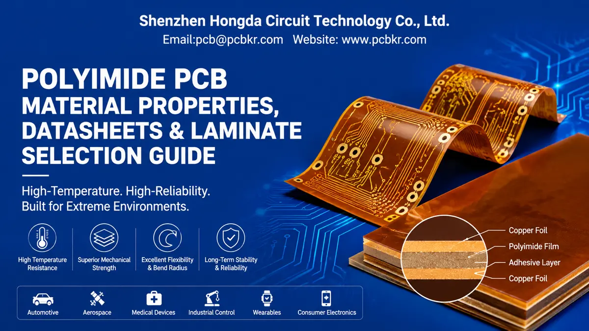
Polyimide PCB Material Properties, Datasheets & Laminate Selection Guide
If you are a hardware engineer or procurement manager staring at a stack of polyimide PCB material datasheets from Dupont, Isola, and Ventec—trying to decide which polyimide PCB laminate will survive your prototype’s thermal profile without delaminating—you are not alone. Most teams default to FR-4, discover it softens above 150 °C, and then scramble to find a high-temperature PCB material that can handle lead-free reflow, underhood automotive cycles, or the bend radius of a wearable device.
This guide is written from the factory floor perspective. At Shenzhen Hongda Circuit Technology, we process polyimide flex circuit material, rigid-flex polyimide material, and polyimide copper clad laminate daily across vacuum lamination presses, UV/CO₂ hybrid laser drills, and mSAP fine-line lines. We have seen what works in prototype volumes and what silently fails six months into a thermal cycling test. The parameters below are the ones our DFM engineers check first when a customer submits Gerbers for a polyimide PCB prototype manufacturing quote.
When Does Your Project Actually Need Polyimide PCB Material Instead of FR-4?
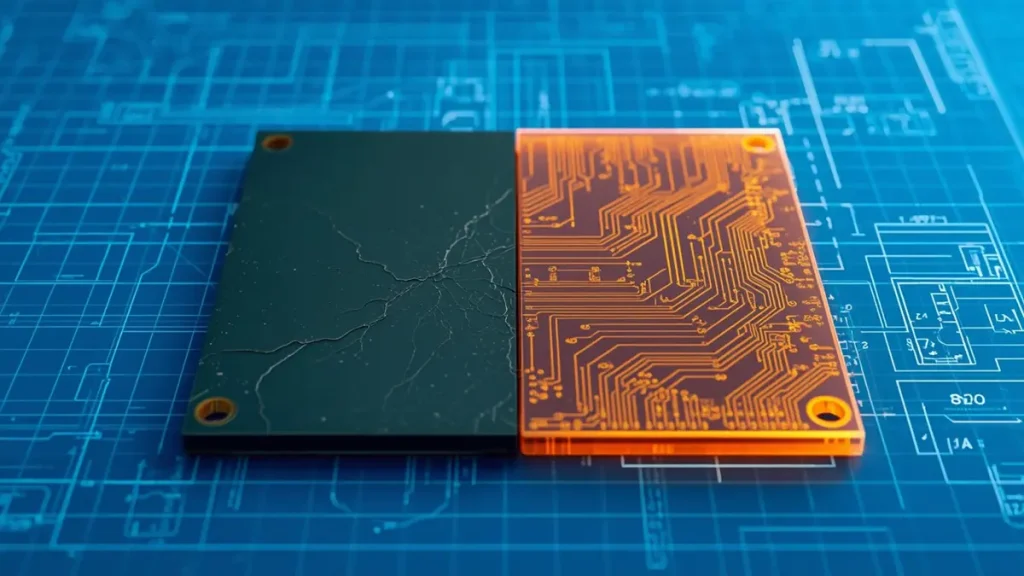
Thermal performance boundary comparison — Standard FR-4 substrate showing micro-cracks under elevated temperatures vs. heat-resistant Polyimide PCB material maintaining structural integrity.
Not every board justifies the cost jump from FR-4 to polyimide PCB substrate properties. The decision point usually arrives when at least one of these three conditions appears in your design review:
- Continuous operating temperature exceeds 150 °C. Standard FR-4 hits its glass transition temperature (Tg) between 130 °C and 170 °C. Above Tg, the epoxy resin softens, Z-axis expansion accelerates, and plated through holes begin to fracture. Polyimide PCB material maintains structural integrity well beyond 250 °C, with some formulations rated for 300 °C continuous operation and short-term exposure above 400 °C.
- Dynamic flexing or tight bend radius. If your assembly folds around a hinge, wraps inside a medical endoscope, or lives in a foldable smartphone, FR-4 will crack after a few cycles. Polyimide’s tensile strength—typically 230–350 MPa—and elongation at break of 6–8 % allow bend radii down to 5 mm or smaller without fatigue failure.
- CTE mismatch with ceramic components or metal housings. Polyimide’s in-plane CTE (12–20 ppm/°C below Tg) sits much closer to copper (17 ppm/°C) than FR-4 does. That matters when you are soldering large BGA packages or bonding the PCB to an aluminum heatsink; the closer the CTE match, the lower the shear stress on solder joints during thermal shock.
If your application checks any of those boxes, continuing with FR-4 is a risk. The polyimide PCB material vs FR4 comparison is not about luxury—it is about whether the board survives validation testing.
Polyimide PCB Material Properties Every Buyer Must Verify Before Placing a Prototype Order
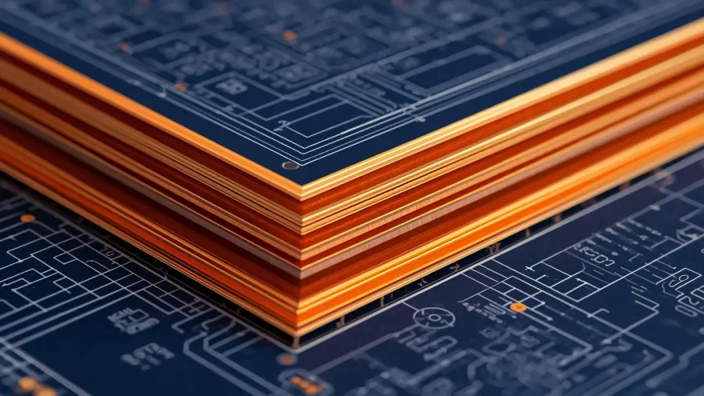
Micro-section view of a multilayer polyimide PCB laminate, illustrating precision copper foil integration and high-Tg dielectric layers.
A polyimide PCB material data sheet can run ten pages and still hide the one parameter that kills your design. Here are the three property clusters our engineering team validates before we even quote a build.
Thermal Endurance: Glass Transition Temperature and Z-Axis CTE
The Tg of polyimide PCB laminate is only the starting point. What separates a reliable board from a field failure is the thermal decomposition temperature (Td) and the Z-axis CTE above Tg.
| Parameter | Typical Polyimide Range | Why It Matters for Procurement |
|---|---|---|
| Glass Transition Temperature (Tg) | > 250 °C (some grades > 400 °C) | Determines the ceiling of your soldering profile |
| Thermal Decomposition (Td) | 550–600 °C | Indicates the point of irreversible chemical breakdown |
| Z-Axis CTE (< Tg) | 30–60 ppm/°C | Affects via barrel reliability during thermal cycling |
| T-288 Time | > 60 minutes | How long the laminate survives at 288 °C before delamination |
At Hongda Circuit, we run incoming material verification on every roll of polyimide PCB laminate using TMA (Thermomechanical Analysis) and TGA (Thermogravimetric Analysis). If the T-288 time falls below 60 minutes, the material lot is rejected before it reaches the vacuum press. That is the difference between a supplier who trusts the mill certificate and one who verifies it.
Electrical Performance: Dielectric Constant and Dissipation Factor at High Frequency
For RF engineers sourcing polyimide PCB material for 5G antenna designs or mmWave radar modules, electrical stability across temperature and humidity is non-negotiable.
| Parameter | Typical Value | Test Frequency / Condition |
|---|---|---|
| Dielectric Constant (Dk) | 3.2–3.6 | @ 10 GHz |
| Dissipation Factor (Df) | 0.001–0.005 | @ 10 GHz |
| Volume Resistivity | 10¹⁵–10¹⁷ Ω·cm | ASTM D257 |
| Dielectric Strength | 120–200 kV/mm | IEC 60243 |
The problem is that Dk drifts with temperature and moisture uptake. A polyimide PCB material with 0.3 % water absorption can see its Dk shift by 0.1–0.2 after humidity conditioning. For a 77 GHz automotive radar board, that shift detunes your patch antenna. We mitigate this by pre-baking panels at 120 °C for 4 hours before lamination and by specifying low-flow polyimide grades for high-frequency builds.
Mechanical Reliability: Peel Strength and Flexural Fatigue Life
Peel strength between copper foil and the polyimide flex circuit material determines whether your traces lift after the first reflow cycle or the 100,000th flex cycle.
| Parameter | Typical Value | Notes |
|---|---|---|
| Peel Strength (1 oz copper) | 0.7–1.2 N/mm | Adhesiveless constructions perform better |
| Tensile Strength | 230–350 MPa | 3× higher than FR-4 |
| Flexural Fatigue Life | > 100,000 cycles @ 5 mm radius | IPC-6013 Class 3 validation |
Adhesiveless polyimide copper clad laminate—where copper is sputtered or electroplated directly onto the film without an acrylic or epoxy bonding layer—delivers 30 % higher peel strength and lower Df. That is why Hongda Circuit defaults to adhesiveless Pyralux-type constructions for dynamic flex applications unless the customer explicitly requests a filled polyimide for rigidity.
Dupont Kapton vs Isola vs Ventec Polyimide PCB Laminate: A Procurement-Side Comparison
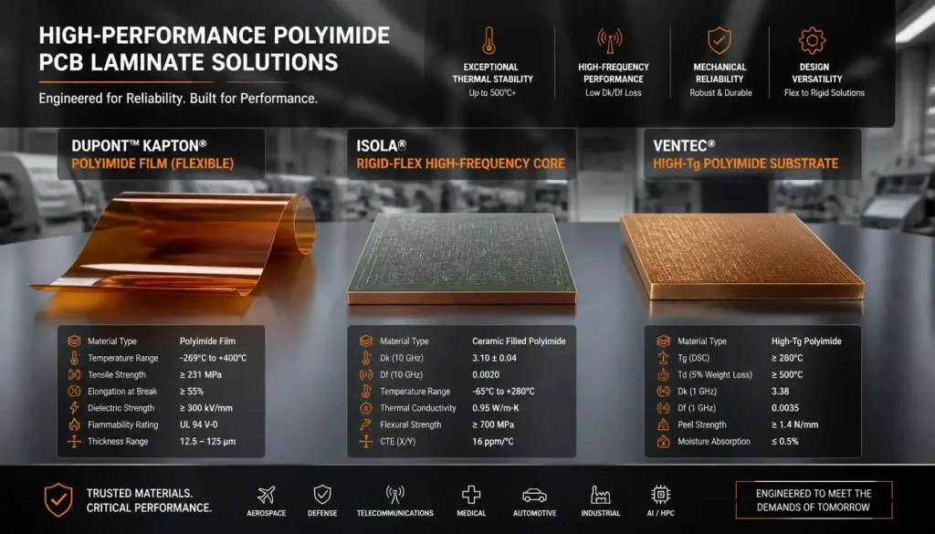
Material comparison chart of Dupont Kapton, Isola, and Ventec polyimide PCB laminates showing core thermal, electrical, and mechanical properties.
You have three dominant brands in the polyimide PCB laminate specification space. The choice is rarely about which is “best” in a laboratory sense; it is about which one aligns with your project’s certification requirements, volume forecast, and supply chain risk tolerance.
Dupont Kapton: The Aerospace Gold Standard with Longest Field Provenance
Dupont’s Kapton series—HN, FN, and the newer colorless CPI grades—sets the baseline for best polyimide PCB material for aerospace. Kapton HN offers Tg > 250 °C, Td > 360 °C, and a proven radiation resistance track record on NASA missions. The downside? Price and lead time. Kapton commands a 15–25 % premium over Asian-sourced alternatives, and mills often require 8–12 week order windows for non-standard thicknesses.
When to specify Kapton:
Your customer requires ESA or NASA certification, or your board operates in a radiation environment where material lot traceability back to DuPont’s Newark, DE facility is mandatory.
Isola Polyimide Laminates for High-Frequency Rigid-Flex Builds
Isola’s polyimide offerings—such as the 33N, 35N, and 37N families—target the rigid-flex polyimide material market where designers need rigid sections for component mounting bonded to flexible Kapton-like sections for interconnect. Isola optimizes these laminates for stable Dk/Df across broad temperature swings, making them popular in 5G base station and satellite communication modules.
When to specify Isola:
You are building a multilayer rigid-flex with controlled impedance traces and need the rigid core and flex core to come from the same certified supplier to simplify stackup management.
Ventec Polyimide Substrates: Balancing Cost and Performance for Volume Production
Ventec’s VT-901 and VT-90H series deliver high Tg polyimide PCB laminate performance (Tg = 250 °C, Td = 395 °C) at a price point that makes sense for automotive and industrial IoT volumes. Ventec has aggressively expanded its China distribution network, which means shorter lead times for Shenzhen-based fabricators like Hongda Circuit.
When to specify Ventec:
You need IPC-4101E-compliant polyimide PCB laminate for a production program where unit cost matters, but you cannot sacrifice Tg or CTE performance.
How to Read a Polyimide PCB Material Data Sheet Without Missing Critical Specifications
A polyimide PCB material data sheet is a legal document written by the material mill’s marketing team. It tells the truth, but not the whole truth. Here is what experienced buyers look for between the lines.
The Hidden Red Flags in Polyimide PCB Material Specifications
- “Typical” vs. “Guaranteed” values. If the Df is listed as “0.003 (typical)” without a tolerance band, assume it can drift to 0.006 in production. Demand a lot-specific certificate of analysis (CoA) for prototype builds.
- Missing T-288 or T-300 data. A polyimide PCB material data sheet that omits T-288 time is often hiding a material that will delaminate during your second lead-free reflow pass.
- CTE reported only below Tg. Z-axis expansion accelerates dramatically above Tg. If the datasheet only lists CTE < Tg, ask for the > Tg value before you commit to a blind via stackup.
Moisture Absorption and Its Impact on High-Frequency Performance
Polyimide absorbs 0.2–0.3 % moisture under 85 °C / 85 % RH conditioning. That seems trivial until you realize that water has a Dk of roughly 80. A 0.2 % moisture uptake can shift your effective Dk by 2–3 %, which is enough to push a 28 GHz 5G antenna off-frequency. For high-frequency builds, we specify pre-bake protocols and vacuum-desiccant packaging at Hongda Circuit to protect the polyimide PCB material between fabrication and assembly.
Polyimide PCB Laminate Manufacturing at Hongda Circuit: Equipment and Process Control
Sourcing a polyimide PCB material supplier in China is easy. Sourcing one that can prove its lamination void rate, laser registration accuracy, and impedance tolerance is harder. Here is how we handle polyimide PCB prototype manufacturing at our Shenzhen facility.
Vacuum Lamination Presses for Void-Free Polyimide Bonding
Polyimide resin flows differently than FR-4 epoxy. It requires slower heat ramps—1–2 °C per minute—and peak temperatures around 350 °C under vacuum to eliminate voids at the copper-to-substrate interface. Our vacuum lamination line uses segmented heating platens with ±2 °C uniformity across a 24 × 18 inch panel. Post-lamination, panels undergo a 200 °C curing cycle to complete imidization without exceeding the 260 °C degradation threshold.
UV and CO₂ Hybrid Laser Drilling for Microvias in Multilayer Polyimide Boards
For polyimide PCB laminate builds with microvias, we operate Mitsubishi UV DPSS lasers (355 nm) alongside CO₂ systems. The UV source handles copper opening and dielectric ablation for vias down to 50 µm in production, with positional accuracy of ±5 µm (3σ). For advanced interposer and substrate-like PCB (SLP) applications, our femtosecond laser platform achieves 20–30 µm vias with minimal heat-affected zone—critical when drilling through thin polyimide flex circuit material without charring the dielectric.
Controlled Impedance Testing and mSAP Process for Sub-15 µm Fine Lines
Modern polyimide PCB material for 5G antenna and high-speed flex designs demand trace widths below 30 µm. Our modified semi-additive process (mSAP) line produces lines and spaces down to 15 µm on polyimide copper clad laminate using sputtered seed layers and electrolytic copper plating. Every panel is verified on a TDR impedance test system before shipment, not just on a coupon.
Polyimide PCB Material Selection by Application: From 5G Antennas to Aerospace Harnesses
The “best” polyimide PCB material is the one that solves your specific failure mode. Here is how we guide customers at the quoting stage.
Aerospace and Satellite: Low CTE and Radiation-Hardened Polyimide Laminates
Satellite PCBs see 20,000+ thermal cycles between -150 °C and +125 °C during a 15-year mission. We recommend Dupont Kapton or UBE Upilex S-grade polyimide PCB substrate properties with Z-axis CTE < 50 ppm/°C and radiation resistance validated to ASTM D5204. Hongda Circuit builds these to IPC-6013 Class 3 with full lot traceability and microsection documentation.
Automotive Underhood: Thermal Cycling Resistance and Chemical Stability
Engine control modules and BMS boards live in environments with oil mist, salt spray, and 150 °C peak temperatures. A filled polyimide PCB laminate with low-flow resin restriction minimizes warpage during lamination and maintains peel strength after 1,000 hours of 85 °C / 85 % RH aging. We pair this with ENIG surface finish for wire-bond compatibility.
5G mmWave and RF Front-End: Stable Dk/Df Across Temperature and Humidity
At 28 GHz and 77 GHz, even a 0.05 shift in Dk changes your antenna beam angle. We specify polyimide PCB material with Df < 0.003 @ 10 GHz and pre-condition all material in a nitrogen dry box before fabrication. Our mSAP process ensures skin-effect copper roughness below 2 µm to minimize conductor loss at mmWave frequencies.
Download Polyimide PCB Material Datasheets and Request a Free Gerber Material Matching Review
You now have the polyimide pcb material properties framework to evaluate Dupont Kapton, Isola, and Ventec laminates against your thermal, electrical, and mechanical requirements. The next step is confirming that your specific stackup, via structure, and component placement actually work with the material you have chosen.
[Download Polyimide PCB Material Datasheet PDFs]
Fill in your name, company email, and application notes. We will send you the latest Dupont Kapton, Isola, and Ventec polyimide PCB material data sheet PDFs directly to your inbox, along with a polyimide PCB material procurement checklist our sourcing team uses for incoming inspection.
[Submit Your Gerber Files for a Free Material Matching & Cost Evaluation]
Upload your Gerber, drill, and stackup files. Within 30 minutes, our DFM engineers will:
- Verify whether your selected polyimide PCB laminate matches your thermal profile
- Flag impedance or via reliability risks
- Provide a firm prototype quote with polyimide PCB material lead time and polyimide PCB laminate thickness options
📧 Email:sales@pcbkr.com
🌐 Website:www.pcbkr.com
📍 Shenzhen Hongda Circuit Technology Co., Ltd.
Room 1608-1610, Research Development Comprehensive Building, Baoyunda Logistics Center, Baoan, Shenzhen, China
Frequently Asked Questions: Polyimide PCB Material Procurement
What is the typical lead time for polyimide PCB prototype manufacturing from a China supplier?
Standard polyimide PCB prototype manufacturing lead times from Shenzhen-based suppliers range from 5 days for simple 2-layer flex builds to 15–20 days for 8+ layer rigid-flex with stacked microvias. At Hongda Circuit, we stock Dupont Kapton, Isola, and Ventec polyimide PCB laminate in common thicknesses, which allows us to deliver standard 4-layer polyimide flex prototypes in 48 hours and complex 10–16 layer rigid-flex builds in 5–7 days. The critical path is usually material availability for non-standard thicknesses below 25 µm or above 125 µm, which can add 1–2 weeks if not inventoried.
How do I verify that a polyimide PCB material supplier actually uses authentic Dupont Kapton or Isola laminates?
Request a Certificate of Analysis (CoA) with lot numbers traceable to the mill, and cross-check the lot number directly with Dupont or Isola’s regional distributor. At Hongda Circuit, we maintain incoming material inspection records including TMA, TGA, and peel strength verification for every roll of polyimide copper clad laminate. We provide these CoA documents to customers upon request, especially for aerospace and medical projects where material authenticity is a contractual requirement. If a supplier cannot produce a mill CoA within 24 hours, that is a red flag.
What is the minimum order quantity (MOQ) for polyimide PCB laminate prototypes?
Most polyimide PCB material suppliers in China impose MOQs of 5–10 panels for prototype builds due to the setup time required for vacuum lamination and laser drilling. However, Hongda Circuit operates a dedicated quick-turn cell for polyimide PCB prototype manufacturing that accepts 1-panel orders for standard material gauges (25 µm, 50 µm, 75 µm PI film). For custom polyimide PCB laminate thickness options or specialized filled polyimide grades, the MOQ typically rises to 3–5 panels because the material must be slit from master rolls. We recommend consolidating prototype variants onto a single panel to optimize material utilization.
How does moisture absorption in polyimide PCB material affect assembly yield?
Polyimide absorbs 0.2–0.4 % moisture by weight under ambient humidity. During reflow soldering at 260 °C, that moisture vaporizes and creates internal pressure—leading to delamination, blistering, or “popcorning” in multilayer builds. The fix is simple but often skipped: pre-bake the bare boards at 120 °C for 2–4 hours before assembly, and store them in vacuum-sealed bags with desiccant until soldering. At Hongda Circuit, we ship all polyimide PCB material boards in moisture-barrier packaging with a humidity indicator card, and we document the bake-out time on the packing slip. Ignoring this step is the leading cause of prototype rework in our experience.
What certifications should a reliable polyimide PCB manufacturer hold for aerospace and automotive projects?
At minimum, look for ISO 9001, IPC-A-600, and IPC-6013 (for flexible boards). For automotive, IATF 16949 is mandatory. For aerospace and defense, AS9100D and ITAR registration (or equivalent export compliance) are required. Hongda Circuit holds ISO 9001, IATF 16949, and UL certifications, and we build to IPC-6013 Class 3 standards for mission-critical polyimide flex circuit material applications. If your project requires ESA or NASA material traceability, verify that the fabricator has direct purchasing agreements with Dupont or Isola—not just distributor receipts—because full lot traceability requires mill-direct documentation.
© 2026 Shenzhen Hongda Circuit Technology Co., Ltd. All technical data reflects actual production parameters and is subject to material lot variation. Contact pcb@pcbkr.com for the latest specifications.
About Author
David Chen https://www.linkedin.com/in/pcbcoming
David Chen boasts an extensive professional background in PCBA manufacturing, PCBA testing, and PCBA optimization, with specialized expertise in high-precision PCBA fault analysis and rigorous PCBA reliability testing. The author has worked with high-layer-count server PCB fabrication, ultra-low-loss backplane stackups, and thermo-mechanical reliability optimization for AI infrastructure projects involving 112G and 224G PAM4 architectures. Skilled in complex circuit design and cutting-edge advanced PCB manufacturing processes, he delivers solutions that elevate product durability and performance across industrial applications. His technical articles focusing on PCBA manufacturing workflows and testing methodologies are widely cited by industry peers, research institutions, and technical platforms, solidifying his reputation as a recognized technical authority in the global circuit board manufacturing sector.