Solar Light PCB Manufacturing for Reliable Outdoor Lighting
What Is a Solar Light PCB and What Does It Control?
A Solar Light PCB manages the charging, battery protection, lighting control, and LED power functions of a solar-powered lighting product. For OEM buyers, the right design depends on the solar panel, battery chemistry, LED load, operating environment, and required control features. Choosing a suitable manufacturing and assembly partner also helps reduce production defects and improve consistency between prototype and volume orders.
Solar light circuit boards are used in garden lights, wall lights, pathway lights, security lighting, solar street lights, and other off-grid lighting products. Depending on the design, a board may contain charging circuitry, a battery protection interface, an LED driver, a light sensor, a motion sensor, or a microcontroller.
For procurement teams, the important question is not simply whether a supplier can manufacture a PCB. It is whether the supplier can meet the project’s electrical, mechanical, thermal, assembly, testing, and delivery requirements.
A custom Solar Light PCB project may require one or more of the following services:
- Bare PCB fabrication from customer-supplied manufacturing files.
- SMT and through-hole component assembly.
- Component sourcing and turnkey PCBA production.
- Programming and functional testing, where applicable.
- Engineering review, prototype builds, and repeat production.
The manufacturing scope should be agreed before quotation so that board fabrication, components, assembly, and testing are not confused or unintentionally omitted.
Which Solar Light PCB Type Is Right for Your Product?
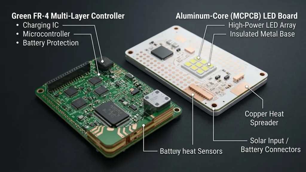
Solar Light PCB Material Comparison: FR-4 Controller vs Aluminum LED Board
The appropriate Solar Light PCB construction depends on the electrical load, heat dissipation requirements, available enclosure space, and target production cost. A low-power garden light and a high-output solar street light should not automatically use the same board structure.
When Is FR-4 Suitable for a Solar Light Controller PCB?
FR-4 is commonly used for controller boards that integrate charging control, battery monitoring, sensors, and other electronic functions. Its suitability depends on the operating temperature, required electrical insulation, mechanical constraints, and component power dissipation.
Single-sided or double-sided FR-4 may be sufficient for relatively simple circuits. More complex designs may require additional copper layers to accommodate routing density, ground returns, power distribution, and control circuitry.
The layer count should follow the circuit requirements rather than being increased without a technical reason.
Before selecting the board construction, buyers should confirm:
- Board dimensions and maximum available thickness.
- Copper thickness and current-carrying requirements.
- Component placement and connector locations.
- Operating temperature and expected power dissipation.
- Surface finish and solderability requirements.
- Mounting holes, mechanical tolerances, and enclosure clearances.
When Should You Choose an Aluminum PCB for Solar Lighting?
An aluminum-based metal-core PCB can be appropriate for solar lighting designs in which the LED board must transfer heat toward a heat sink or metal enclosure.
Unlike a conventional FR-4 board, an aluminum PCB uses a thermally conductive dielectric layer between the circuit copper and the metal base. Its thermal performance depends on the dielectric properties, copper pattern, LED layout, board-to-housing interface, and overall cooling design.
Aluminum is not automatically the best choice for every part of a solar light. The control circuit and LED array may have different thermal and electrical requirements.
For example, a design may use an FR-4 controller board and a separate aluminum LED board. This arrangement can simplify thermal management and make the controller easier to assemble or service.
Should the Controller PCB and LED Board Be Manufactured Separately?
A combined board may reduce connector count and assembly steps when the mechanical and thermal design permits it. A separate controller and LED board may provide greater flexibility when the LED load generates substantial heat or the controller requires independent servicing.
| Design consideration | Combined board | Separate controller and LED boards |
|---|---|---|
| Assembly | Potentially fewer interconnections | Additional connectors or wiring may be needed |
| Thermal management | Depends on the complete board design | Controller and LED thermal paths can be optimized separately |
| Mechanical integration | Requires compatible component and enclosure layouts | Allows more flexible placement |
| Maintenance | A fault may require replacing the combined assembly | Individual assemblies may be replaceable |
| Cost | Depends on board construction and production volume | Depends on connectors, wiring, assembly, and board complexity |
The best option should be evaluated using the complete product design rather than the PCB unit price alone.
Which Electrical Specifications Must Be Defined Before Solar Light PCB Manufacturing?
The electrical specification determines whether the PCB can safely manage the available solar energy, battery charging, and lighting load. A manufacturer needs the relevant electrical and mechanical requirements to assess manufacturability and provide a meaningful quotation.
How Should Solar Panel Input and Battery Charging Requirements Be Specified?
The solar charging circuit must be compatible with the photovoltaic panel and the selected rechargeable battery.
The design documentation should identify:
- Solar panel nominal operating voltage and open-circuit voltage.
- Expected input current and power range.
- Battery chemistry, nominal voltage, capacity, and cell configuration.
- Required charging profile and charge-current limits.
- Low-voltage cutoff and battery protection requirements.
- Reverse-polarity and reverse-current protection, where required.
- Operating temperature range and relevant abnormal conditions.
Battery chemistry matters because different battery systems require different charging limits and control strategies. A design intended for one battery chemistry should not be assumed compatible with another simply because their nominal voltages are similar.
The PCB manufacturer should fabricate and assemble the board to the approved design. Changes to charging algorithms, component values, or protection behavior should be reviewed and approved by the responsible design authority.
How Do You Calculate the Energy Budget for Nighttime Lighting?
The energy budget connects the battery, solar panel, LED load, and expected operating schedule.
For an initial estimate, the energy consumed by the lighting load can be expressed as:
Lighting energy per night = LED electrical power × operating hours
For example, a 6 W LED load operating for 8 hours consumes 48 Wh before accounting for driver losses and other system loads.
The battery must provide sufficient usable energy for the intended operating conditions. The final calculation should also account for conversion efficiency, battery operating limits, aging, temperature, and the expected variation in solar charging conditions.
A simplified battery energy estimate is:
Nominal battery energy = nominal battery voltage × rated capacity in ampere-hours
This is an initial sizing relationship, not a guarantee of usable energy. The battery’s discharge limits and the system’s actual operating conditions determine how much energy is available.
Procurement teams should confirm that the selected PCB and its components support the intended charging current, discharge current, LED power, and protection strategy. These requirements may affect component selection, copper thickness, connector ratings, and thermal design.
How Should LED Current, Copper Thickness, and Trace Width Be Selected?
Power-carrying traces must be designed for the expected current, allowable voltage drop, copper thickness, and temperature rise.
A trace that is adequate for a low-current sensor circuit may not be suitable for the LED power path. Likewise, a connector or solder joint can become a limiting factor even when the PCB traces are correctly sized.
During design review, consider:
- Continuous and peak current.
- Trace width, copper thickness, and copper geometry.
- Permitted voltage drop across power paths.
- Thermal interaction with nearby components.
- Connector, terminal, and solder-joint ratings.
- Current return paths and ground layout.
Trace dimensions should be determined from the actual design requirements and the applicable engineering calculation method. There is no single trace width that is appropriate for every Solar Light PCB.
When Is MPPT Necessary for a Solar Light Controller PCB?
Maximum power point tracking (MPPT) adjusts the operating point of a photovoltaic source to extract available power under changing conditions.
An MPPT controller may be useful when the solar panel, battery system, operating profile, and energy-harvesting objectives justify its additional complexity. Simpler charging approaches may be appropriate for lower-cost products with different performance requirements.
The decision should consider expected solar conditions, panel characteristics, charging efficiency, component cost, control complexity, and firmware requirements.
MPPT should be specified when it provides a meaningful system-level benefit, not added merely as a marketing feature.
Which PCB Materials and Thermal Design Options Work Best Outdoors?
Material selection must account for electrical performance, temperature, moisture exposure, mechanical construction, and the intended service environment. Outdoor reliability depends on the complete lighting product, not on the PCB material alone.
Is FR-4 or Aluminum PCB Better for Solar Lighting?
FR-4 and aluminum-core PCBs serve different design needs.
FR-4 is suitable for many control and signal-processing circuits. Aluminum-core construction is often considered for LED boards that need an effective path for conducting heat away from the LEDs.
The decision should be based on the board’s function, thermal load, electrical isolation requirements, mounting arrangement, and manufacturing cost.
For a controller PCB, the key issue may be stable operation of the charging circuit and microcontroller. For a high-power LED board, junction temperature and the thermal path into the housing may dominate the design.
A thermal review should examine the entire heat path, including the component package, solder interface, copper pattern, dielectric layer where applicable, board base, thermal interface material, and enclosure.
How Do Copper Thickness and Thermal Vias Affect Heat Dissipation?
Copper distributes heat and current across a PCB, but its effectiveness depends on the complete layout and construction. Thermal vias can transfer heat between copper layers when the stack-up and via arrangement provide a useful thermal path.
For aluminum-core boards, the metal base and dielectric layer are important parts of the thermal design. For FR-4 boards, copper planes, thermal vias, component placement, and external cooling can influence temperature distribution.
The design should be reviewed against the actual power dissipation and the available cooling conditions. Adding copper or thermal vias without considering the rest of the thermal path does not guarantee a specific temperature reduction.
How Should a Solar Light PCB Be Protected Against Moisture and Corrosion?
Outdoor lighting products may encounter rain, humidity, condensation, dust, temperature cycling, and contaminants. The level of protection required depends on the enclosure, installation environment, and intended operating life.
Possible design measures include:
- Appropriate conformal coating or encapsulation where justified.
- Suitable connectors, terminals, and cable-entry arrangements.
- Adequate spacing and layout around exposed conductive features.
- Corrosion-aware material and surface-finish selection.
- Drainage, ventilation, and condensation management at the product level.
- Validation of seals, enclosure interfaces, and coating coverage.
Conformal coating can reduce exposure of the assembly to selected environmental hazards, but it is not a substitute for a properly designed enclosure. A coated PCB alone does not establish an IP rating for the complete lighting product.
Coating compatibility with connectors, switches, sensors, test points, and repair requirements should also be reviewed before production.
How Can Solar Light PCB Design Prevent Field Failures?
Field reliability improves when foreseeable electrical, thermal, and environmental failure mechanisms are addressed during design review and verified through appropriate testing. A PCB supplier should understand the approved requirements and flag manufacturability concerns before production.
Why Do Solar Light PCBs Fail to Charge or Switch On at Night?
A solar light that does not charge or illuminate may have several possible causes.
| Observed symptom | Possible causes | Useful checks |
|---|---|---|
| Battery does not charge | Insufficient panel input, charging-circuit fault, wiring issue, or protection activation | Measure panel input and charging behavior against the design specification |
| Light does not turn on at night | Incorrect sensor threshold, depleted battery, control logic issue, or LED driver fault | Verify sensor response, battery state, control signals, and driver output |
| Light switches on during the day | Sensor placement, threshold setting, ambient light conditions, or wiring issue | Check sensor operation and the specified switching threshold |
| Runtime is shorter than expected | Insufficient stored energy, excessive LED load, conversion losses, or battery degradation | Compare measured consumption and available battery energy with the energy budget |
| Board operates intermittently | Loose connections, solder defects, thermal issues, or moisture-related damage | Inspect connections, solder joints, temperatures, and environmental exposure |
These are diagnostic possibilities, not definitive fault conclusions. Troubleshooting should follow measured evidence and the product’s approved circuit documentation.
How Can LED Flicker, Excessive Heat, and Short Runtime Be Diagnosed?
LED flicker may originate from unstable power conversion, current regulation, control behavior, poor connections, or a battery supply problem. Excessive temperature may result from insufficient thermal design, an unsuitable operating point, excessive current, or inadequate heat transfer to the enclosure.
Short runtime can arise from battery capacity, charging conditions, LED power consumption, driver efficiency, or the operating schedule.
A useful investigation compares the observed behavior with defined acceptance criteria. Relevant measurements may include input voltage, charging current, battery voltage, LED current, output stability, component temperature, and operating duration.
Where a fault is reproducible, documenting the operating conditions and test results helps the engineering team distinguish a PCB manufacturing defect from a design, component, battery, or enclosure issue.
Which Protection Circuits Should Be Evaluated?
Protection requirements depend on the product architecture and the consequences of a fault.
Potential functions include:
- Reverse-polarity protection.
- Overcurrent and short-circuit protection.
- Battery overcharge and over-discharge protection.
- Overtemperature protection.
- LED open-circuit and short-circuit response.
- Reverse-current protection between relevant power stages.
Not every product needs every protection function on the same PCB. Some functions may be implemented in the battery pack, charger IC, LED driver, firmware, or other subsystem.
The schematic and bill of materials should identify where each required function is implemented. Validation should then verify the expected behavior under the specified normal and abnormal conditions.
How Are Solar Light PCBs Manufactured and Assembled?
Solar Light PCB production generally involves engineering review, bare-board fabrication, component assembly where required, inspection, electrical testing, and shipment approval. The exact process depends on whether the buyer needs a bare PCB, an assembled board, or a more complete manufacturing service.
What Happens During PCB Fabrication and DFM Review?
Before manufacturing, the fabrication data should be checked against the approved specifications.
A design for manufacturability (DFM) review may cover:
- Gerber or ODB++ data and drill files.
- Board outline, dimensions, and mechanical features.
- Layer count, stack-up, finished thickness, and copper weight.
- Minimum trace and spacing requirements.
- Pad geometry, solder mask, and surface finish.
- Panelization and production handling.
- Critical tolerances and inspection requirements.
If a discrepancy is identified, the manufacturer should clarify the issue before changing the production data. Unapproved changes to the layout, materials, or dimensions can create problems during assembly or final product integration.
For OEM buyers, revision control is particularly important when the same Solar Light PCB will be manufactured repeatedly. The production files, BOM, assembly instructions, and acceptance criteria should refer to the correct revision.
How Are Components Sourced and Assembled?
PCBA assembly adds components to the fabricated circuit board using processes appropriate to the package types and design.
Depending on the project, assembly may include SMT, through-hole technology (THT), or a combination of both. Component sourcing may be handled by the customer or included in a turnkey manufacturing arrangement.
A clear PCBA specification should define:
- Approved BOM and component manufacturer part numbers.
- Component sourcing responsibility.
- Rules for substitutions and obsolete parts.
- Pick-and-place data and assembly drawings.
- Polarity, orientation, and special soldering requirements.
- Programming and functional testing, where applicable.
Substitutions should be reviewed for electrical, thermal, mechanical, and regulatory compatibility. A component with a similar footprint is not necessarily an acceptable replacement.
Which Manufacturing Details Affect Repeatability?
Consistent volume production depends on more than producing a functioning prototype. The manufacturing process must preserve the approved design, component selection, workmanship requirements, and inspection criteria across batches.
Important controls include first-article review, assembly inspection, controlled BOM revisions, traceable production records, and documented handling of nonconforming products.
AOI can help detect selected soldering and component-placement defects. Electrical tests can identify certain open or short circuits, while functional tests can verify specified operating behavior. Each method has limitations, so the inspection plan should reflect the risks of the particular board.
For repeat orders, the supplier should be able to identify the applicable production revision and document any approved engineering changes.
For a broader overview of manufacturing services, see the PCB Manufacturer page from Shenzhen Hongda Circuit Technology Co., Ltd.
Which Tests Should a Solar Light PCB Pass Before Shipment?
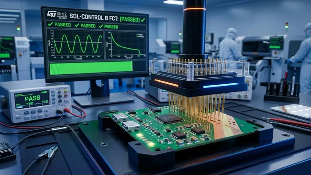
Solar Light PCBA Functional Testing (FCT) in Smart SMT Factory
Testing should be based on the approved design, product risk, and agreed acceptance criteria. A bare PCB and a fully assembled Solar Light PCBA require different test plans.
What Should Be Checked During PCB Electrical Testing?
Bare-board testing may include electrical continuity and isolation checks on the relevant networks, according to the fabrication requirements and test coverage.
Additional inspection may verify board dimensions, copper features, solder mask, surface finish, and other specified manufacturing characteristics.
The purchase order should identify which tests are included, the applicable acceptance requirements, and any reports or records required for shipment.
How Should PCBA Functional Testing Verify Charging and LED Operation?
Functional testing evaluates the assembled board under defined electrical and operating conditions.
Depending on the product, a test plan may include:
- Power-input and current-consumption checks.
- Battery charging behavior.
- LED driver output and lighting control.
- Day-night switching and sensor response.
- Required protection functions.
- Communication or programming checks, where applicable.
A dedicated fixture may improve repeatability when the board has defined test points and measurable operating states. Test limits should be derived from the approved product specification rather than invented during production.
Where the solar panel, battery, or complete lighting enclosure is not included in the assembly order, the buyer and manufacturer should agree how those system-level functions will be simulated or verified.
How Can Environmental and Thermal Risks Be Validated?
Environmental validation should reflect the intended installation and operating conditions.
Depending on the project, engineering validation may include temperature exposure, humidity or condensation evaluation, thermal measurements, vibration testing, or corrosion-related assessment.
These tests are not interchangeable. A PCB that passes a functional test at room temperature has not automatically demonstrated long-term outdoor reliability.
Buyers should distinguish between:
- Design validation, which evaluates whether the design meets its requirements.
- Production testing, which checks defined characteristics of manufactured units.
- Product-level validation, which evaluates the complete lighting assembly and enclosure.
The required test methods, sample quantities, acceptance criteria, and reporting responsibilities should be agreed before the project enters production.
How Much Does a Solar Light PCB Cost?
Solar Light PCB cost depends on the board design, manufacturing specifications, order quantity, component requirements, and delivery conditions. PCBA pricing also depends on sourcing, assembly complexity, programming, and the agreed test scope.
A meaningful quotation requires enough information to distinguish a simple bare board from a complete assembled controller.
Which PCB Specifications Have the Biggest Impact on Cost?
Key cost drivers include:
- Board dimensions and panel utilization.
- Number of layers and stack-up complexity.
- Base material and copper thickness.
- Finished board thickness and dimensional tolerances.
- Surface finish and any special fabrication requirements.
- Order quantity and production batch size.
- Inspection requirements and delivery schedule.
Aluminum-core LED boards and FR-4 controller boards have different construction and thermal requirements. Comparing their prices without considering their functions can lead to misleading purchasing decisions.
Similarly, a lower initial board price does not necessarily mean a lower total project cost if the design requires additional assembly steps, rework, or integration changes.
How Do PCBA Component Sourcing and Testing Change the Quote?
For assembled boards, the quotation may include component procurement, PCB fabrication, SMT or THT assembly, programming, testing, and packaging.
The BOM is especially important because component availability, manufacturer part numbers, package types, and approved alternatives can affect both price and lead time.
Testing also affects cost. A standard visual inspection is not equivalent to a dedicated functional test using a fixture, programmed controller, battery simulator, or LED load.
The quotation should state what is included and identify exclusions such as customer-supplied components, special tooling, third-party certification, or complete product assembly.
How Can Buyers Reduce Total Cost Without Increasing Failure Risk?
Cost optimization should focus on removing unnecessary complexity while preserving the product’s essential electrical, thermal, and environmental requirements.
Practical opportunities may include:
- Reviewing board dimensions and panel utilization.
- Using suitable standard materials and surface finishes.
- Simplifying the assembly where the electrical design permits.
- Selecting available components with approved alternatives.
- Combining production orders when demand and revision control allow.
- Defining test requirements according to actual product risks.
- Resolving DFM issues before production tooling and materials are committed.
Changes to copper thickness, protection circuits, component ratings, or environmental safeguards should not be made solely to achieve a lower quotation. Any engineering change must be reviewed against the product requirements.
How Do You Choose a Reliable Solar Light PCB Manufacturer?
A reliable Solar Light PCB manufacturer should demonstrate that it can meet the required board specifications, assembly scope, quality controls, and production schedule. Procurement teams should evaluate documented capabilities and project-specific evidence rather than relying on general marketing claims.
Which PCB and PCBA Capabilities Should You Verify?
Start by confirming whether the supplier can manufacture the required board construction and complete the necessary assembly processes.
Check the supplier’s capabilities against your actual requirements for materials, copper thickness, board dimensions, component packages, SMT or THT assembly, and testing.
If the project needs turnkey PCBA, establish who is responsible for component sourcing, approved substitutions, programming, and functional testing.
A supplier that can fabricate the bare PCB may not automatically offer every assembly or system-integration service required for the finished product.
What Quality Records and Test Evidence Should You Request?
Ask for quality records that relate directly to the product and the supplier’s stated manufacturing scope.
Useful evidence may include:
- Relevant process and inspection records.
- First-article or prototype inspection results.
- Electrical or functional test results, as applicable.
- Material and component traceability records.
- Approved revision and engineering change records.
- Corrective-action documentation when a nonconformance occurs.
- Certificates that apply to the relevant facility, process, and product scope.
Certification claims should be verified for their validity and applicability. A management-system certificate alone does not prove that a particular Solar Light PCB meets every product requirement.
Can One Supplier Support Prototype, Small-Batch, and Volume Production?
A supplier may support multiple production stages, but the buyer should verify the actual arrangements for each stage.
For prototypes, the priorities often include engineering communication, design review, and the ability to identify issues quickly. During pilot production, repeatability, assembly controls, and test coverage become more important. Volume production requires consistent revisions, material availability, process control, and delivery planning.
Ask how the supplier handles changes between prototype and production, including updated Gerber files, BOM revisions, component substitutions, and revised test limits.
These controls are important because a prototype that works correctly does not, by itself, prove that a production process is ready for repeated orders.
How Should You Compare Quotes from Different PCB Suppliers?
Compare quotations using the same technical specification and commercial assumptions.
| Comparison item | What to confirm |
|---|---|
| PCB construction | Material, layer count, thickness, copper weight, and finish |
| Manufacturing data | File revision, dimensions, tolerances, and panelization |
| PCBA scope | Assembly processes, components, and sourcing responsibility |
| Testing | Inspection coverage, functional tests, and reports |
| Component substitutions | Approval process and traceability |
| Delivery | Quoted lead time, quantity, and shipment terms |
| Quality management | Relevant records, acceptance criteria, and corrective actions |
| Commercial terms | Tooling, setup charges, packaging, and excluded costs |
The lowest quotation is not necessarily the best choice if it omits required tests, uses unapproved substitutions, or leaves important technical requirements undefined.
A comparable quotation should make the manufacturing scope and assumptions explicit so that purchasing decisions reflect both cost and project risk.
What Files Are Required for a Solar Light PCB Quote?
The information needed for a quotation depends on whether the buyer requires bare PCB fabrication, PCBA assembly, or a broader manufacturing service. Providing complete and consistent files helps the supplier evaluate the design and identify unresolved requirements.
What Should You Send for Bare PCB Manufacturing?
For a bare-board quotation, prepare the available manufacturing files and specifications, including:
- Gerber or ODB++ fabrication data.
- NC drill files and board outline.
- Layer count and stack-up information.
- Finished board thickness and copper weight.
- Surface finish and solder mask requirements.
- Critical dimensions and tolerances.
- Order quantity and requested delivery date.
If any specification is not yet finalized, identify it as an open item rather than assuming the manufacturer will select it without approval.
What Additional Files Are Needed for PCBA?
An assembly quotation generally requires additional information:
- Bill of Materials with manufacturer part numbers.
- Pick-and-place or centroid data.
- Assembly drawings and polarity information.
- Approved component alternatives, if any.
- Firmware or programming instructions, where applicable.
- Functional test requirements and acceptance limits.
- Packaging, labeling, and traceability requirements.
If the buyer needs turnkey PCBA, the quotation should distinguish supplier-sourced components from customer-supplied materials and identify how shortages or substitutions will be handled.
Can You Request a Quote Before All Specifications Are Final?
Yes. A preliminary quotation may be possible when the buyer provides enough information to define the approximate board construction, assembly scope, and order quantity.
However, missing electrical requirements, incomplete manufacturing data, or an unapproved BOM may prevent the supplier from confirming a final price or delivery schedule.
A useful preliminary RFQ should identify known requirements, unresolved design decisions, target quantities, and the expected next milestone. This allows the manufacturer to explain which missing details must be resolved before production.
Frequently Asked Questions About Choosing a Solar Light PCB Supplier
How Do I Find a Solar Light PCB Manufacturer for OEM Production?
Search for manufacturers that explicitly support the board construction and production scope required by your project. Review their PCB fabrication, PCBA assembly, component sourcing, testing, and revision-control capabilities. Before placing an order, provide the manufacturing files and request a quotation that clearly defines the included services, acceptance criteria, and delivery assumptions.
What Information Should I Send When Requesting a Solar Light PCB Quote?
For bare PCB fabrication, provide Gerber or ODB++ files, drill data, board dimensions, layer count, copper thickness, surface finish, quantity, and delivery requirements. For PCBA, also provide the BOM, assembly files, component sourcing requirements, and functional test specifications. Identify any unresolved design parameters so the supplier can explain their effect on price and manufacturability.
How Can I Verify the Quality of a Solar Light PCBA Supplier?
Request evidence relevant to the manufacturing scope, such as inspection records, electrical or functional test results, material traceability, and engineering change controls. Confirm which tests are performed on the bare PCB and which are performed on the assembled board. Verify any claimed certifications and determine whether they apply to the actual facility and process involved in your order.
Can a Solar Light PCB Manufacturer Handle Both Prototypes and Mass Production?
Some manufacturers support prototypes, small batches, and volume production. Buyers should confirm the supplier’s actual capacity and how it controls design revisions, BOM changes, component substitutions, and test procedures as production scales. A successful prototype is a useful starting point, but production readiness should also be supported by repeatable assembly processes and documented acceptance criteria.
What Should I Compare When Choosing Between Solar Light PCB Suppliers in China?
Compare the same technical specification across all quotations, including PCB construction, component sourcing, assembly scope, testing, traceability, delivery terms, and excluded costs. Evaluate the supplier’s engineering response and ability to identify technical gaps before production. A low price should not take priority over compliance with the approved design and the quality requirements of the finished lighting product.
Request a Solar Light PCB Manufacturing Quote from Hongda Circuit
Choosing the right Solar Light PCB manufacturing partner starts with a clear specification and a defined production scope. Whether your project requires bare PCB fabrication, assembled controller boards, or a turnkey PCBA arrangement, the quotation should reflect the electrical design, materials, components, inspection requirements, and intended production volume.
Shenzhen Hongda Circuit Technology Co., Ltd. works with customers on PCB manufacturing and PCBA requirements according to the agreed project specifications. Share the available design files and purchasing requirements so the manufacturing scope can be reviewed before the order is finalized.
To request a Solar Light PCB quote, prepare:
- Gerber or ODB++ files and the latest approved revision.
- BOM and assembly files, if PCBA is required.
- Board material, dimensions, thickness, and copper requirements.
- Order quantity and expected production schedule.
- Electrical, functional, and quality acceptance criteria.
- Any special environmental, packaging, or traceability requirements.
Contact: sales@pcbkr.com
Website: https://www.pcbkr.com/
For related manufacturing information, visit the PCB Manufacturer service page and submit your project requirements for review.
About Author
David Chen https://www.linkedin.com/in/pcbcoming
David Chen is a Senior RF/PCB Process Engineer at Shenzhen Hongda Circuit Technology Co., Ltd., with over 12 years of experience in high-frequency PCB fabrication, impedance-controlled stack-up design, and Rogers/PTFE laminate processing. He also boasts an extensive professional background in PCBA manufacturing, PCBA testing, and PCBA optimization, with specialized expertise in high-precision PCBA fault analysis and rigorous PCBA reliability testing. The author has worked with high-layer-count server PCB fabrication, ultra-low-loss backplane stackups, and thermo-mechanical reliability optimization for AI infrastructure projects involving 112G and 224G PAM4 architectures. Skilled in complex circuit design and cutting-edge advanced PCB manufacturing processes, he delivers solutions that elevate product durability and performance across industrial applications. His technical articles focusing on PCBA manufacturing workflows and testing methodologies are widely cited by industry peers and technical platforms, and have gained attention and recognition from industry colleagues.