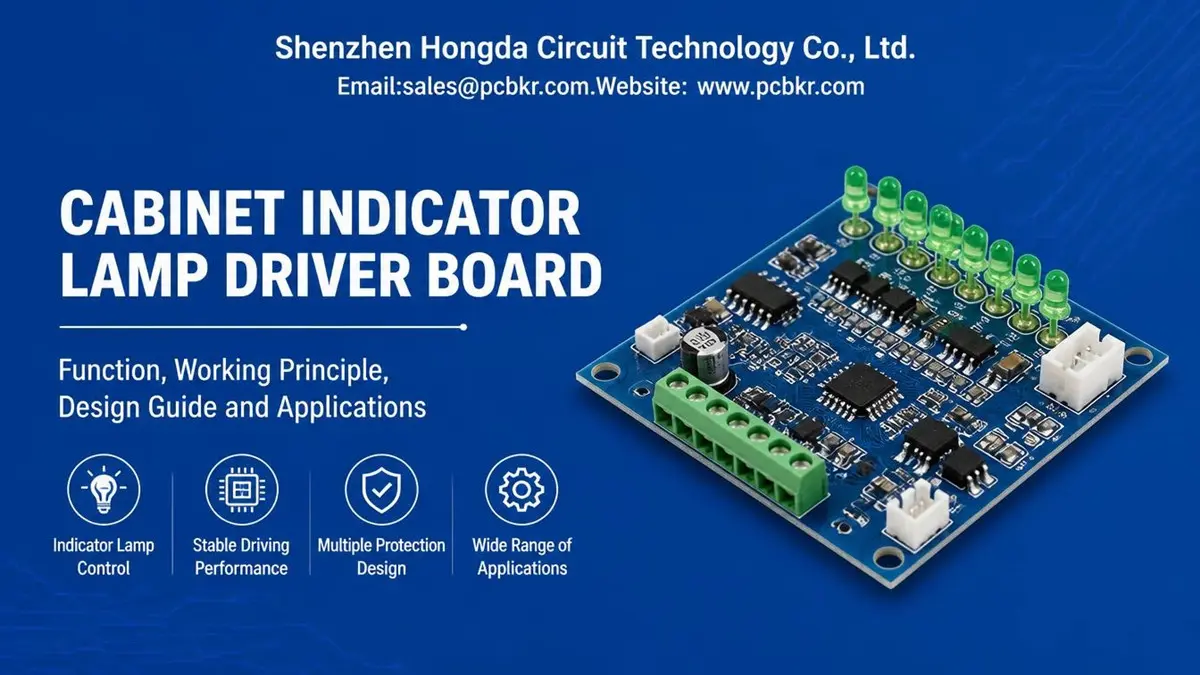
Cabinet Indicator Lamp Driver Board Manufacturer
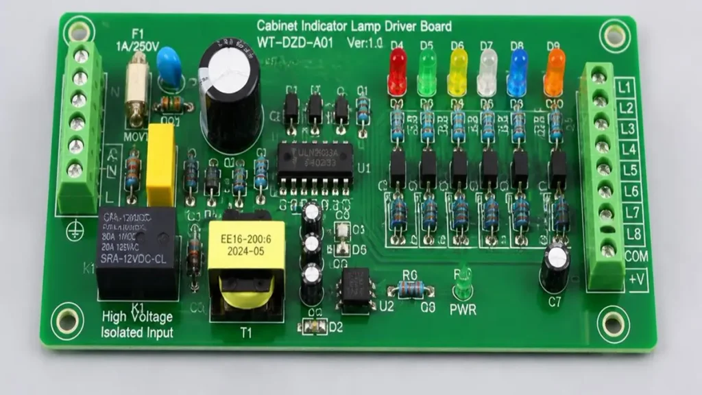
PCB Material:FR-4 / High-Tg FR-4
PCB Layers:2–4 Layers
Board Thickness:1.0–1.6 mm
Copper Thickness:1–2 oz
Minimum Trace Width / Spacing:0.15 / 0.15 mm
Minimum Finished Hole Diameter:0.20 mm
A cabinet indicator lamp driver board controls LED status lamps in industrial control cabinets, electrical distribution panels, and automation equipment. Its design must match the system’s input voltage, PLC output type, indicator channels, and operating environment. PCBKR provides PCB fabrication and PCBA assembly support for custom industrial control boards, from prototype builds to production orders, with manufacturing and inspection processes selected according to each project’s requirements.
What Is a Cabinet Indicator Lamp Driver Board?
A Cabinet Indicator Lamp Driver Board is an electronic control board that receives status or control signals and drives indicator lamps to display equipment operating conditions. Depending on the application, it may control individual LEDs, multiple indicator channels, or groups of panel-mounted status lamps.
Unlike a simple LED connection board, an industrial indicator driver board may need to handle different input signals, supply conditions, output currents, and fault conditions. Its circuit design should therefore be based on the electrical interface and operating requirements of the cabinet in which it will be installed.
Main Functions and Applications
A cabinet indicator lamp driver board may perform several functions:
- Status indication: Displays operating, standby, alarm, fault, and maintenance states.
- Signal conditioning: Adapts PLC or controller signals to the electrical requirements of LED indicator circuits.
- LED current control: Limits or regulates current to help maintain stable indicator brightness.
- Multi-channel control: Drives several independent indicator lamps from one PCB.
- Electrical protection: Provides appropriate protection against reverse polarity, voltage transients, and output faults.
- Signal isolation: Separates field-side signals from control electronics when the system design requires isolation.
Typical applications include:
- Industrial control cabinets
- Electrical distribution and switchgear panels
- PLC control panels
- Machine control systems
- Power supply and motor control cabinets
- Industrial automation equipment
- Monitoring and alarm indication units
The required functions vary by application. A board that only drives a few 24 V DC indicator LEDs may need a relatively simple circuit. A board connected to multiple PLC outputs or exposed to electrical disturbances may require additional signal conditioning, protection, and isolation.
Industrial Control Cabinet Indicator Configurations
The indicator arrangement should be defined before the PCB layout is finalized. Common configurations include:
| Configuration | Typical design consideration |
|---|---|
| Single-channel indicator | Input voltage, LED current, polarity, and protection |
| Multi-channel indicator | Number of channels, independent control, common connections, and channel spacing |
| PLC-controlled indicator | Output type, signal polarity, sourcing or sinking interface |
| Alarm indicator | Flashing logic, fault priority, and visible status differentiation |
| Isolated indicator interface | Isolation voltage, grounding arrangement, and signal-side power |
| Combined indicator and control board | Separation of control signals, power circuits, and indicator outputs |
The number of channels and the type of indicator lamps affect component selection, connector layout, copper routing, and the overall PCB dimensions. These requirements should be included in the initial design package rather than resolved after the board has entered production.
How Does a Cabinet Indicator Lamp Driver Board Work?
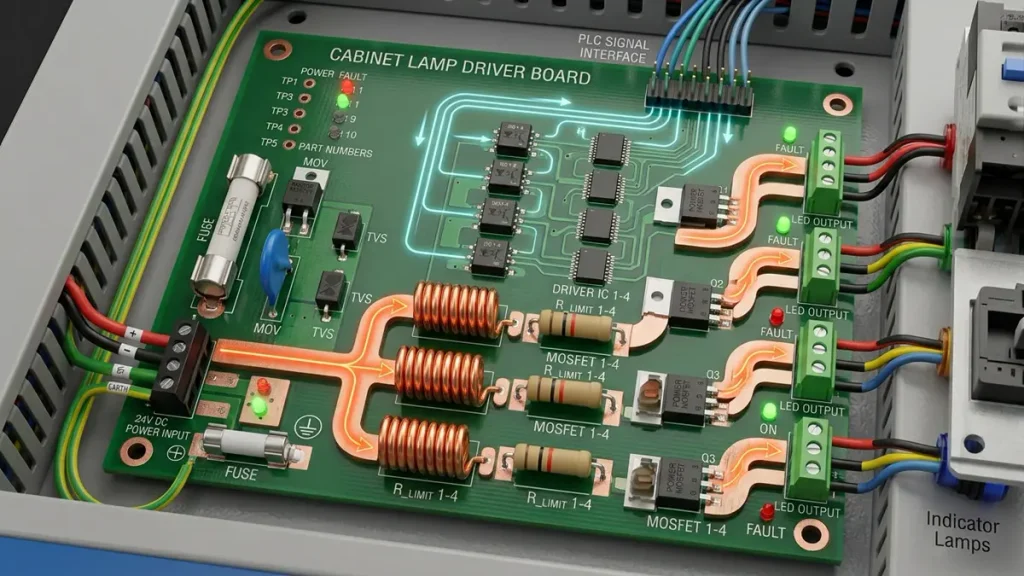
Cabinet Indicator Lamp Driver Board Circuit Design
A cabinet indicator lamp driver board receives an electrical input or control signal, processes it through the appropriate interface circuit, and supplies the required current to the indicator LED or lamp. The actual circuit architecture depends on the input supply, controller output, number of indicators, and required operating logic.
24V DC Input and Power Regulation
Many industrial control systems use 24 V DC control supplies. However, the board should not be designed on the assumption that every cabinet provides an identical voltage condition.
The design review should confirm:
- Nominal input voltage and permitted operating range
- Input polarity and connector pin assignment
- Expected voltage variation during equipment operation
- Input surge and transient conditions
- Whether the indicator circuit shares a supply with other loads
- Whether local voltage regulation is required
If the board includes logic devices, communication interfaces, or other components operating at lower voltages, a suitable DC/DC converter or linear regulator may be required.
The input protection and power regulation circuits should be selected according to the actual electrical environment. Component voltage ratings, power dissipation, PCB copper area, and thermal conditions should be checked together.
LED Current Control and Driver Circuits
An LED requires current control. Connecting an LED directly to a voltage source without an appropriate current-limiting method can cause excessive current and premature failure.
Depending on the LED characteristics and operating requirements, the board may use:
- Series current-limiting resistors
- Constant-current driver circuits
- Transistor or MOSFET output stages
- Integrated multi-channel LED driver ICs
- PWM control where adjustable brightness or flashing is required
A resistor-based circuit may be sufficient for a simple indicator application. A constant-current driver may be more suitable when consistent current is required across multiple LEDs or when supply and LED forward-voltage variations need to be managed.
The design should also consider resistor power ratings, driver IC dissipation, output current limits, and the effect of simultaneous channel operation.
Multi-Channel Indicator Control
A multi-channel board can control several indicator lamps independently. Each channel may correspond to a machine state, operating condition, alarm, or control signal.
The main design considerations include:
- Channel count: Confirm the total number of indicator outputs and whether future expansion is required.
- Output current: Calculate the maximum current per channel and the combined load when multiple indicators are active.
- Control logic: Define whether each channel is independently switched, dimmed, or configured for flashing.
- Fault behavior: Determine what happens when an LED is open-circuit, short-circuit, or disconnected.
- Connector assignment: Keep channel identification and wiring consistent with the cabinet drawings.
For larger channel counts, an integrated LED driver or shift-register-based architecture may reduce component count and simplify control. The selected solution must still meet the required output current, diagnostic, and thermal conditions.
PLC Signal Interface and Output Compatibility
PLC compatibility is a critical design issue. A driver board that is electrically incompatible with the PLC output may produce incorrect indication, fail to switch reliably, or remain partially illuminated when the output is inactive.
Before selecting the input circuit, confirm whether the PLC uses:
- PNP or NPN transistor outputs
- Sourcing or sinking output arrangements
- Relay outputs
- High-side or low-side switching
- Shared or isolated common connections
The board input circuit may use a resistor network, transistor stage, optocoupler, or other signal-conditioning circuit, depending on the interface requirements.
The design review should verify the input threshold, input current, polarity, common reference, and signal behavior in both active and inactive states. Solid-state PLC outputs may also have leakage current when switched off. If this leakage is sufficient to cause a low-current LED to glow, the board may need an appropriate input or output circuit to prevent false indication.
The PLC model, wiring diagram, output specifications, and expected signal logic should therefore be included in the RFQ documentation.
What Electrical Protection Features Should an Industrial Indicator Driver Board Have?
Protection requirements depend on the cabinet power system, connected loads, wiring length, and operating environment. A protection circuit should address identified electrical risks without adding unnecessary components or creating incompatibility with the control system.
Reverse Polarity and Overvoltage Protection
Reverse polarity can damage electronic components when the supply is connected incorrectly. Depending on the input voltage and available space, protection may use a series diode, MOSFET-based reverse-polarity circuit, or another suitable arrangement.
Overvoltage protection may include:
- Transient voltage suppressor (TVS) devices
- Input filtering
- Appropriate voltage-rated components
- Protection coordinated with the upstream power supply
- Circuit-level clamping where required
The protection design should be based on the expected transient waveform, energy level, and source impedance. A TVS component should not be selected solely by its nominal voltage; its clamping characteristics and power rating must also be checked.
LED Open-Circuit and Short-Circuit Protection
An open-circuit LED generally causes the affected indicator channel to stop illuminating. A short circuit can create excessive current or trigger protection in the output driver, depending on the circuit architecture.
Possible design measures include:
- Individual current limiting for each LED channel
- Output current limiting
- Driver ICs with open-load or short-circuit diagnostics
- Channel-level protection
- Fault feedback to the controller, where required
Not every indicator board needs electronic fault reporting. For a simple board, current limiting and suitable component ratings may be sufficient. For systems where an incorrect status indication could affect maintenance or operation, diagnostic feedback may be worth including.
EMI Filtering and Transient Suppression
Industrial cabinets can contain switching power supplies, contactors, relays, motors, and other sources of electrical noise. The indicator board should be reviewed for susceptibility to conducted and radiated interference.
Depending on the system, the design may require:
- Input filtering
- Local decoupling capacitors
- Suitable grounding and return paths
- Separation between noisy switching circuits and sensitive signal inputs
- Protection at external connector interfaces
- Appropriate routing of high-current and low-level signal paths
Filter components and PCB layout should be considered together. A filter placed far from the connector or protected circuit may not provide the intended result.
Thermal Management and Continuous Operation
Indicator boards may remain powered for long periods, even when the controlled equipment is not actively operating. Continuous operation makes component temperature and power dissipation important design considerations.
The engineering review should check:
- LED and driver current
- Resistor power dissipation
- Regulator and driver IC losses
- Copper area around heat-generating components
- Enclosure temperature and airflow
- Component derating under the expected operating conditions
The board should be evaluated under the intended combination of supply voltage, channel loading, and ambient temperature. If the application requires continuous operation, testing should reproduce a representative load condition rather than checking only whether the LEDs turn on.
How Should a Cabinet Indicator Lamp Driver PCB Be Designed and Manufactured?
PCB design and manufacturing decisions affect electrical performance, assembly quality, mechanical fit, and production consistency. The board stack-up and fabrication process should be selected from the circuit requirements rather than from a fixed layer count or material specification.
PCB Material and Layer Selection
FR-4 is commonly suitable for conventional industrial indicator driver boards. High-Tg FR-4 may be considered when the design or assembly process requires a higher glass-transition-temperature material or when the expected thermal conditions justify it.
The material decision should consider:
- Operating temperature
- Board dimensions and mechanical support
- Copper weight
- Component density
- Required electrical insulation
- Assembly thermal exposure
- Production cost and availability
Many straightforward indicator driver boards can be manufactured using a two-layer PCB. Additional layers should be considered only when required by routing density, grounding, isolation, signal integrity, or mechanical constraints.
PCBKR supports PCB fabrication for different layer counts and material requirements. For industrial control applications involving customized circuit layouts, material selection, and board construction, buyers can also explore our Intelligent Industrial Control PCBs manufacturing capabilities. The final material and stack-up should be confirmed against the Gerber data, electrical requirements, and approved manufacturing documentation.
Copper Thickness and Current Routing
Copper thickness and trace geometry should be selected according to the current carried by each path, allowable temperature rise, copper distribution, and available board area.
For a multi-channel driver board, the design review should distinguish between:
- Input power traces
- Shared supply and return paths
- Individual LED channel outputs
- Driver IC power connections
- Low-current control signals
The combined current through a shared power path may be higher than the current through any single LED channel. Connector ratings, copper thickness, trace width, vias, and terminal spacing should all be checked against the maximum expected load.
For higher-current designs, PCBKR’s fabrication process can support the required copper and board construction when the design is within the confirmed production specification. Final trace geometry and copper thickness must be reviewed against the customer’s current and temperature-rise requirements.
Trace Width, Clearance and Via Design
Trace width should be calculated from current, copper thickness, and the permitted temperature rise. Clearance should be determined from working voltage, transient conditions, applicable safety requirements, and the customer’s design rules.
Via design should consider:
- Current carried by the via
- Finished hole diameter
- Copper plating thickness
- Number of parallel vias
- Board thickness
- Thermal and mechanical requirements
For boards with fine-pitch components or dense routing, PCBKR uses SCREEN Ledia LDI direct imaging equipment. The stated process target is 8 µm imaging capability with ±10 µm process tolerance. This is a manufacturing-process capability, not a default trace-width or spacing guarantee for every board. The achievable geometry must be confirmed for the actual material, copper thickness, panel construction, and production process.
Where the design requires laser-drilled microvias, PCBKR has Mitsubishi UV/CO₂ laser drilling capability with a stated 75 µm ±5 µm process range, as well as picosecond laser processing down to 50 µm. These processes are relevant only when the board architecture requires the corresponding microvia or fine-feature construction. A conventional indicator driver board may not need them.
Grounding, Isolation and PCB Layout
The PCB layout should maintain clear separation between power switching paths, control signals, and sensitive input circuits.
Important layout checks include:
- Keeping high-current return paths away from sensitive signal references
- Avoiding unnecessary shared impedance between channels
- Providing local decoupling near driver IC power pins
- Maintaining suitable spacing around protection components
- Defining the isolation boundary where optocouplers or isolated power are used
- Placing connectors to match the cabinet wiring and mechanical arrangement
Where isolation is required, the design must define the working voltage, isolation rating, creepage, clearance, and relevant safety requirements. A PCB layout should not rely on an arbitrary slot or spacing value without considering the applicable system requirements.
For multilayer constructions, PCBKR uses controlled lamination processes. Its LAUFFER lamination equipment supports process pressures of 80, 150, and 200 psi, with a stated vacuum level below 50 mbar. These process controls support multilayer board fabrication where the selected stack-up requires them. They are not a requirement for every two-layer indicator board.
SMT Assembly and Component Placement
Component placement affects assembly yield, solder-joint reliability, electrical performance, and serviceability.
During assembly planning, the following should be reviewed:
- Component package and footprint compatibility
- Connector orientation and mechanical access
- Polarity marking for LEDs, diodes, and electrolytic capacitors
- Thermal spacing around power components
- Solder-joint accessibility
- Test-point placement
- Board edge and mounting-hole clearances
PCBKR provides SMT and THT assembly support according to the project BOM and assembly drawings. The assembly process should use approved component specifications, soldering profiles, and inspection criteria.
PCBKR provides SMT and THT assembly support according to the project BOM and assembly drawings. For projects requiring customized controller boards and integrated electronic assembly, buyers can also review our Embedded Control Board OEM manufacturing service. The assembly process should use approved component specifications, soldering profiles, and inspection criteria.
What Testing Is Required for Cabinet Indicator Lamp Driver PCBA?
Testing should verify the board’s electrical connections, assembly quality, and required operating functions. The appropriate inspection plan depends on the component packages, circuit complexity, order quantity, and customer acceptance criteria.
Incoming Component Inspection
Before assembly, the BOM and supplied components should be checked against the approved documentation.
Typical checks include:
- Part number and manufacturer verification
- Package and footprint confirmation
- Quantity and reference designator checks
- Polarity-sensitive component identification
- Review of approved alternative components
- Handling requirements for moisture-sensitive devices, where applicable
Component substitutions should not be made solely because a part has a similar package or nominal value. The replacement must meet the electrical and mechanical requirements of the original design.
SMT and THT Assembly Inspection
Assembly inspection checks whether components have been placed and soldered according to the assembly data.
PCBKR has 3D AOI inspection capability for checking visible component placement and solder-joint conditions. This is particularly relevant to SMT assemblies where polarity, orientation, missing components, and placement defects need to be identified.
For assemblies containing hidden solder joints, such as certain BGA or other bottom-terminated packages, X-ray inspection can be used when the package structure and inspection plan require it. X-ray is not necessary for every indicator driver board; its use should be determined by the actual component package and quality requirements.
THT connectors and other through-hole components should also be checked for correct orientation, seating, solder fill, and mechanical stability.
Electrical Continuity and Functional Testing
Electrical testing should be based on the approved schematic and test specification.
Depending on the design, the test plan may include:
- Power input polarity verification
- Supply voltage and current measurement
- Short-circuit checks on power rails
- Continuity checks on critical nets
- Individual LED channel activation
- Simultaneous multi-channel operation
- Input threshold and PLC interface verification
- Reverse-polarity or protection-circuit verification, where specified
- Open-circuit and short-circuit response, where diagnostic functions are included
PCBKR has four-wire Kelvin flying probe testing capability. This method can support electrical verification of PCB connections and resistance-sensitive measurements where the test setup and board design are suitable. It does not replace functional testing of the assembled indicator driver circuit.
For PCBA orders, a functional test fixture can be defined from the customer’s test requirements. The fixture should reproduce the required input signals, output loads, channel states, and acceptance limits.
LED Channel and Protection Circuit Verification
A functional test should confirm that each indicator channel responds to the correct control signal and produces the expected output.
A typical test matrix may include:
| Test item | Verification purpose |
|---|---|
| Input power check | Confirm the board powers up within the specified range |
| Channel-by-channel activation | Verify each LED output independently |
| Simultaneous channel operation | Check shared supply and return paths under combined load |
| PLC input compatibility | Confirm the expected response to the specified input type |
| Inactive-state check | Identify unintended illumination or false triggering |
| Reverse-polarity test | Verify protection behavior if required by the specification |
| Open/short fault test | Confirm the defined fault response if the circuit includes diagnostics |
| Temperature-related check | Evaluate component heating under the specified operating condition |
The test limits, sample size, and pass/fail criteria should be agreed before production. Tests involving abnormal input conditions should be performed using a controlled procedure that does not expose operators or equipment to unnecessary risk.
Production Consistency and Traceability
A successful prototype does not automatically establish production consistency. For repeat orders, the manufacturer should control the approved Gerber revision, BOM revision, assembly drawing, process instructions, and test specification.
Production records may include:
- PCB fabrication lot information
- Material and process records, where specified
- Assembly inspection results
- Electrical test records
- Functional test results
- Nonconformance and rework records
- Approved engineering changes
PCBKR’s inspection and manufacturing processes can be configured according to the customer’s quality plan. The applicable records and traceability level should be confirmed during the RFQ and order review.
How Can Buyers Select a Reliable Cabinet Indicator Lamp Driver Board Manufacturer?
A suitable manufacturer should be able to review the electrical design, fabricate the PCB, assemble the components, and perform the inspections required by the project. Buyers should evaluate the complete manufacturing process rather than compare suppliers only by quoted PCB price.
PCB and PCBA Manufacturing Capabilities
Check whether the supplier can support the required board construction and assembly process.
The review should cover:
- PCB layer count and finished board thickness
- Base material and copper thickness
- Minimum trace width and spacing
- Finished hole and via requirements
- Surface finish
- SMT and THT assembly
- Connector and mechanical requirements
- Inspection and functional testing
PCBKR supports PCB fabrication and PCBA assembly for prototype, small-batch, and production requirements. Its available processes include LDI imaging, multilayer lamination, laser drilling, SMT/THT assembly, 3D AOI, X-ray inspection, and four-wire Kelvin flying probe testing. The processes applied to a specific order depend on the board design and agreed inspection plan.
Component Sourcing and BOM Management
For turnkey PCBA projects, the manufacturer should review the BOM for part availability, package compatibility, lifecycle risks, and approved alternatives.
Buyers should provide:
- Complete BOM with manufacturer part numbers
- Approved vendor list, if applicable
- Restricted or prohibited component substitutions
- Critical component identification
- Customer-supplied versus manufacturer-sourced component allocation
Any proposed alternative should be submitted for approval when it changes the electrical specification, package, thermal behavior, or reliability of the original part.
Prototype and Mass Production Support
Prototype production is useful for checking mechanical fit, connector orientation, signal behavior, and indicator visibility before volume manufacturing.
Before moving to production, buyers should confirm:
- Whether the prototype uses the intended production materials
- Whether the PCB and PCBA revisions are controlled
- Whether the functional test procedure is repeatable
- Whether approved component sources are available
- Whether the manufacturer can maintain the required inspection records
PCBKR supports prototype, small-batch, and mass-production requirements. The production route and lead time should be confirmed after reviewing the actual files, component availability, and order quantity.
Engineering Documentation and Quality Control
A supplier’s ability to work from controlled technical documentation is important for repeatable manufacturing.
The buyer should confirm that the supplier can review and manage:
- Gerber or ODB++ fabrication data
- PCB stack-up and fabrication notes
- BOM and approved component alternatives
- Pick-and-place files
- Assembly drawings
- Electrical test requirements
- Functional test procedures
- Engineering change records
For PCB fabrication, PCBKR can review the design against its manufacturing processes and discuss potential DFM issues before production. For PCBA, the review should also cover component placement, soldering access, connector orientation, test points, and functional test requirements.
What Information Is Required for a Custom Cabinet Indicator Lamp Driver Board RFQ?
A complete RFQ package helps the manufacturer evaluate manufacturability, component sourcing, assembly requirements, and testing scope. Buyers should provide the following information wherever available.
Gerber, BOM and Pick-and-Place Files
The core manufacturing package should include:
- Gerber or ODB++ files
- PCB fabrication drawing
- Layer stack-up, if specified
- Bill of Materials (BOM)
- Pick-and-place or centroid file
- Assembly drawing
- Schematic, where available
- Existing test procedure, if applicable
If the design is still under development, provide the latest available schematic and PCB files together with the expected changes. The manufacturer can then identify information that needs clarification before quotation.
Input Voltage, Channel Count and Output Requirements
Electrical requirements should include:
- Nominal input voltage and operating range
- AC or DC input type
- Input polarity
- Number of indicator channels
- LED or lamp type
- Required current per channel
- Simultaneous channel loading
- Brightness or flashing requirements
- PLC output type: PNP, NPN, sourcing, sinking, or relay
- Isolation requirements
- Protection and diagnostic functions
If the board connects to an existing PLC or controller, include the relevant output specifications and wiring diagram. These documents are important for verifying interface compatibility.
Mechanical Dimensions and Connector Specifications
The mechanical package should identify:
- Finished PCB dimensions
- Board thickness
- Mounting-hole locations and sizes
- Connector part numbers and pin assignments
- Cable or terminal requirements
- Component height restrictions
- Enclosure clearance
- Indicator location and visibility requirements
Mechanical constraints should be confirmed before PCB fabrication. Changes to connector positions or mounting holes after production begins can result in board redesign and additional cost.
Testing and Delivery Requirements
The RFQ should also define:
- Prototype and production quantities
- Required delivery schedule
- PCB-only or complete PCBA requirement
- Turnkey or consigned component sourcing
- Required AOI, X-ray, electrical, or functional tests
- Test fixture requirements
- Inspection records and traceability expectations
- Packaging and shipping requirements
For a custom Cabinet Indicator Lamp Driver Board quotation, send the available technical files and project requirements to sales@pcbkr.com. PCBKR can review the PCB fabrication and PCBA assembly scope and clarify any missing information before confirming the manufacturing proposal.
Frequently Asked Questions
Can a Cabinet Indicator Lamp Driver Board Be Customized for Different PLC Systems?
Yes. The input circuit can be designed around the PLC output type, signal polarity, voltage range, and common connection arrangement. The PLC model and output specifications should be provided during the design review to confirm electrical compatibility.
Can One Indicator Driver Board Control Multiple LED Lamps?
Yes. A multi-channel board can control multiple indicator lamps independently. The channel count, output current, combined load, connector arrangement, and control logic must be defined before the PCB layout is finalized.
What PCB Material Is Suitable for an Industrial Indicator Driver Board?
FR-4 is commonly suitable for conventional indicator driver boards. High-Tg FR-4 may be considered when the operating temperature or assembly requirements justify it. The final material should be selected according to the board’s thermal, electrical, mechanical, and manufacturing requirements.
Does a Cabinet Indicator Lamp Driver PCBA Require X-Ray Inspection?
Not necessarily. 3D AOI can inspect visible SMT assembly conditions, while X-ray is useful for selected components with hidden solder joints. The inspection method should be selected according to the actual component packages and the customer’s quality requirements.
What Files Are Needed to Get a Custom Indicator Driver Board Quotation?
The main files are Gerber or ODB++ data, BOM, pick-and-place file, assembly drawing, and schematic where available. The RFQ should also specify input voltage, PLC interface, channel count, LED current, board dimensions, order quantity, and required testing.
Request a Custom Cabinet Indicator Lamp Driver Board Quote
PCBKR supports custom PCB fabrication and PCBA assembly for industrial control and indicator applications. Send your Gerber or ODB++ files, BOM, electrical specifications, and target quantity for an engineering and manufacturing review.
Email: sales@pcbkr.com
Website: www.pcbkr.com
About Author
David Chen https://www.linkedin.com/in/pcbcoming LinkedIn Profile(锚文本)
David Chen is a Senior RF/PCB Process Engineer at Shenzhen Hongda Circuit Technology Co., Ltd., with over 12 years of experience in high-frequency PCB fabrication, impedance-controlled stack-up design, and Rogers/PTFE laminate processing. He also boasts an extensive professional background in PCBA manufacturing, PCBA testing, and PCBA optimization, with specialized expertise in high-precision PCBA fault analysis and rigorous PCBA reliability testing. The author has worked with high-layer-count server PCB fabrication, ultra-low-loss backplane stackups, and thermo-mechanical reliability optimization for AI infrastructure projects involving 112G and 224G PAM4 architectures. Skilled in complex circuit design and cutting-edge advanced PCB manufacturing processes, he delivers solutions that elevate product durability and performance across industrial applications. His technical articles focusing on PCBA manufacturing workflows and testing methodologies are widely cited by industry peers and technical platforms, and have gained attention and recognition from industry colleagues.
The quotation scope can be reviewed for PCB fabrication, component sourcing, SMT/THT assembly, inspection, and functional testing according to the project requirements.
Cabinet Indicator Lamp Driver Board – Technical Data Sheet
| Parameter | Specification |
|---|---|
| Product Type | Cabinet Indicator Lamp Driver Board |
| Application | Industrial Control Cabinets, Electrical Distribution Panels, Automation Equipment |
| PCB Material | FR-4 / High-Tg FR-4 |
| PCB Layers | 2–4 Layers |
| Board Thickness | 1.0–1.6 mm |
| Copper Thickness | 1–2 oz |
| Minimum Trace Width / Spacing | 0.15 / 0.15 mm |
| Minimum Finished Hole Diameter | 0.20 mm |
| Surface Finish | HASL / Lead-Free HASL / ENIG |
| Solder Mask | Green / Blue / Black / Other Colors |
| Input Voltage | 12 V DC / 24 V DC / Customized |
| LED Driver Type | Current-Limiting Resistor / Constant-Current Driver / MOSFET Driver |
| Output Channels | Single-Channel / Multi-Channel |
| Control Interface | PLC Signal / PNP / NPN / Relay / Customized |
| Protection Features | Reverse Polarity / Overvoltage / Overcurrent / Short-Circuit Protection (As Required) |
| Assembly Technology | SMT / THT / Mixed Assembly |
| Inspection | 3D AOI / X-Ray (When Required) |
| Electrical Testing | Flying Probe Test / Continuity Test |
| Functional Testing | LED Channel Verification / Input-Output Signal Testing (As Specified) |
| Production Volume | Prototype / Small Batch / Mass Production |
Technical Note: The specifications above are indicative reference values for product development and quotation purposes, not fixed manufacturing guarantees. Final PCB materials, layer count, board thickness, copper weight, trace width/spacing, finished hole diameter, electrical functions, and inspection requirements must be confirmed based on the Gerber files, BOM, circuit design, LED load requirements, PLC interface specifications, and customer technical documentation.