How Can OEM Buyers Source a Reliable Fan PCB Manufacturer?
PCB Base Material: FR-4; High-Tg FR-4 according to operating temperature requirements
Layer Count: 2–6 layers, depending on circuit complexity
Board Thickness: 1.0–2.0 mm; customized thickness available
Copper Thickness: 1 oz (35 μm) standard; 2 oz (70 μm) for higher-current designs
Minimum Trace Width / Spacing: 0.10 / 0.10 mm (4 / 4 mil), subject to design review
Minimum Finished Hole Diameter: 0.20 mm, subject to aspect ratio and board thickness
A reliable fan PCB manufacturer must deliver more than a fabricated circuit board: the PCB, components, assembly process, and inspection plan must match the fan motor’s electrical and operating requirements. Shenzhen Hongda Circuit Technology Co., Ltd. (PCBKR) provides custom PCB manufacturing and PCBA assembly, including SMT and through-hole assembly, for OEM projects. Send your Gerber files, BOM, and project requirements to sales@pcbkr.com for a manufacturing review and quotation.
1. What Is a Fan PCB and What Does a Fan Control Board Do?
A fan PCB is the printed circuit board used to connect and manage the electronic functions of a fan. Depending on the product architecture, it may distribute power, switch or regulate a motor, receive user commands, monitor feedback signals, and interface with protection circuits.
For OEM manufacturers, the term fan PCB can refer to different board types:
- Fan power board: distributes or conditions electrical power for the fan system.
- Fan motor control PCB: carries the motor-drive and related control circuitry.
- Fan interface board: connects buttons, displays, remote receivers, sensors, or communication interfaces.
- Fan main control board: combines several of these functions on one PCB.
These functions do not necessarily require one board. Some fan products use a single integrated control PCBA, while others separate the power stage, motor drive, and user interface.
When sourcing a custom fan PCB, buyers should first establish whether they need bare PCB fabrication, assembled PCBA, or both. The distinction affects the quotation package, component procurement, assembly process, and testing requirements.
PCBKR supports PCB fabrication and PCBA assembly according to customer-supplied design data and project requirements. The actual circuit functions and product-level performance remain defined by the approved design and agreed validation plan.
2. Which Types of Fan Control PCBs Can Be Manufactured?
Fan control boards are not interchangeable simply because they are used in products that move air. Motor type, input voltage, current, control method, enclosure, and operating environment all affect the PCB construction and assembly requirements.
| Fan application | Typical electronic requirements | Manufacturing considerations |
|---|---|---|
| DC fan | DC power input, switching or speed-control circuit, motor interface | Current path, connector rating, polarity, and power-component placement |
| BLDC fan | Motor-drive stage, control signals, and feedback interfaces where required | Power-device footprint, gate-drive circuitry, sensing connections, and thermal layout |
| AC fan | Mains-related switching or control circuit, depending on motor topology | Voltage spacing, insulation requirements, component ratings, and applicable safety standards |
| HVAC or ventilation fan | Fan control interface, power connections, and application-specific signals | Operating temperature, vibration exposure, wiring connections, and enclosure constraints |
| Industrial cooling fan | Application-dependent motor drive and monitoring interfaces | Current capacity, environmental conditions, mechanical robustness, and maintainability |
The final architecture must follow the customer’s electrical design. An AC fan control board and a BLDC fan controller may have different power stages, isolation requirements, and component layouts. A supplier should not quote them as equivalent products based only on board dimensions.
For buyers sourcing multiple electronic boards across an appliance range, PCBKR also provides broader home appliance control board PCB and PCBA manufacturing. A dedicated fan PCB project should still be evaluated against its own motor and electrical specifications.
3. What Components Are Used in a Fan Motor Control PCB?
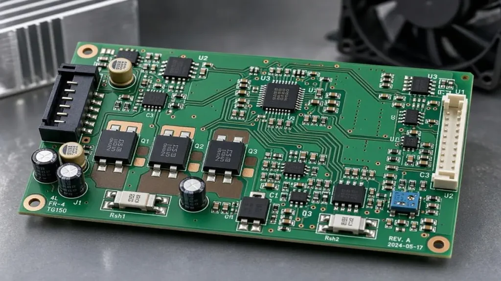
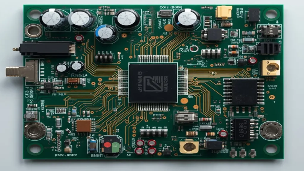
Key electronic components on a fan motor control PCB, including MOSFETs, capacitors, control ICs, and motor connectors.
The component list depends on the motor type and control architecture. A typical fan motor control PCBA may include the following groups:
| Component group | Typical examples | What buyers should confirm |
|---|---|---|
| Power input | Terminals, connectors, protection components | Input voltage, current, polarity, and connection method |
| Power conversion | Rectifiers, regulators, capacitors, inductors | Electrical ratings, temperature ratings, and approved part numbers |
| Motor drive | MOSFETs, switching devices, gate-driver ICs, relays, or triacs as applicable | Device rating, package, thermal conditions, and circuit topology |
| Control | MCU or dedicated control IC | Exact part number, package, and programming responsibility |
| Feedback and sensing | Current-sense resistors, Hall-sensor interfaces, tachometer inputs, temperature sensors | Signal level, routing, connector pinout, and test access |
| User interface | Buttons, LEDs, display connectors, remote receiver interfaces | Mechanical position, polarity, and interface compatibility |
| Interconnection | Wire-to-board connectors, headers, terminals | Pin assignment, retention, mating part, and mechanical loading |
A component name alone is not enough for procurement approval. The manufacturer should work from the approved BOM and manufacturer part numbers wherever possible.
For example, two MOSFETs with similar headline voltage ratings may differ in package, thermal resistance, gate characteristics, and footprint. Substituting one for another without engineering approval can affect both electrical behavior and assembly compatibility.
QFN and other small-outline packages also require attention to land patterns, stencil design, solder-paste volume, reflow conditions, and inspection access. Through-hole connectors may need additional mechanical consideration if the fan harness is frequently connected, disconnected, or exposed to vibration.
PCBKR can manufacture and assemble boards using the customer’s approved design and BOM. Component sourcing or alternative-part evaluation should be confirmed separately for each project; unapproved substitutions should not be treated as automatic production decisions.
4. What PCB Specifications Matter for Fan Control Applications?
A useful RFQ specification describes the actual electrical and mechanical conditions rather than relying on a generic request for a “high-quality fan PCB.”
The following information helps the manufacturer evaluate the design before quotation.
| Specification | Information to provide | Why it matters |
|---|---|---|
| Motor type | AC, brushed DC, BLDC, or other specified type | Determines the control and power-stage architecture |
| Input voltage | Nominal voltage and operating range | Defines component and insulation requirements |
| Operating current | Continuous current and peak or startup current | Affects copper sizing, power components, and connectors |
| PCB dimensions | Length, width, thickness, outline, and mounting holes | Confirms mechanical compatibility |
| Copper thickness | Required finished copper thickness | Influences conductor resistance and thermal behavior |
| Layer count | Required or proposed layer construction | Affects routing, return paths, and board cost |
| Material | FR-4 or another specified material | Must match temperature, electrical, and mechanical requirements |
| Surface finish | ENIG, lead-free HASL, or another specified finish | Depends on component pitch, assembly, and product requirements |
| Connectors | Part number, pinout, current rating, and mating details | Prevents harness and assembly mismatches |
| Operating environment | Ambient temperature, humidity, vibration, and enclosure conditions | Helps establish reliability and validation requirements |
Copper thickness and trace width should be evaluated together with current, conductor length, copper location, allowable temperature rise, and the surrounding thermal environment. A trace-width estimate without these inputs is not a sufficient design approval.
For compact fan controllers, board outline and connector location can be just as important as the electrical layout. A board that passes electrical inspection may still fail during product integration if mounting holes, terminal positions, or component heights do not match the enclosure.
Buyers should provide mechanical drawings or a sample board when dimensional constraints are critical.
5. How Should Fan PCBs Handle Current, Voltage, and Thermal Loads?
Motor-control boards often combine power components and low-level control signals in a limited area. The PCB must support the intended electrical load while keeping temperature rise and voltage drop within the design limits.
Current capacity should be evaluated from the real operating conditions. The review should consider:
- Continuous and peak motor current.
- Startup or transient current.
- Copper thickness and conductor width.
- Trace length and current-return path.
- Via count and current distribution between layers.
- Connector and terminal ratings.
- Permitted temperature rise inside the final enclosure.
A common sourcing mistake is to compare boards using copper thickness alone. Two boards with the same nominal copper weight can perform differently because of trace geometry, thermal paths, component placement, and airflow.
Thermal review should include the power devices, switching components, rectifiers, resistors, and other parts that dissipate significant heat. The enclosure also matters. A fan controller mounted in a confined plastic housing may experience different temperatures from the same PCB operating in an open test fixture.
For higher-power applications, the engineering review may need to assess copper distribution, thermal reliefs, via structures, component spacing, and the use of a metal-core construction where appropriate. PCBKR’s metal core PCB manufacturing capability may be relevant when the project requires a metal-core board structure, subject to the design and thermal requirements.
No universal copper thickness or trace width is suitable for every fan controller. The customer and manufacturer should agree on the operating conditions, acceptance limits, and validation method before production release.
6. How Can EMI and Electrical Noise Be Controlled in Fan PCBs?
Fan controllers may contain switching power circuits, motor-drive signals, sensor inputs, and communication interfaces. Poor layout or grounding can allow switching noise to interfere with control signals or connected electronics.
EMI performance depends on the complete electrical design and product configuration, not just the PCB material or layer count.
During design review, engineering teams should pay attention to:
- Power-current loops: Keep high-current switching paths compact where the circuit topology allows.
- Grounding strategy: Define return-current paths and avoid routing sensitive signals through noisy current-return regions.
- Switching-node copper: Control the area and routing of fast-switching nodes according to the circuit design.
- Decoupling: Place bypass and bulk capacitors according to the IC and power-stage requirements.
- Signal separation: Consider the routing relationship between motor-drive signals, current sensing, tachometer signals, and communication lines.
- Cable interfaces: Review connector pinout, cable length, shielding, and grounding where relevant.
- Enclosure integration: Evaluate the assembled fan product because wiring and mechanical structures can affect emissions and susceptibility.
For BLDC applications, current-sense signals and rotor-feedback signals may be sensitive to switching noise. Their routing should follow the control-circuit requirements rather than being treated as ordinary low-priority connections.
A PCB manufacturer can review manufacturability and assembly-related risks, but PCB fabrication alone cannot guarantee that a finished fan product will pass EMC testing. Compliance depends on the complete design, enclosure, cables, operating modes, and applicable test standards.
If EMC performance is a contractual requirement, buyers should provide the target-market standard, test configuration, and acceptance criteria before production approval.
7. What Are the Common Fan PCB Failure Modes and How Can They Be Prevented?
A reliable supplier should be able to discuss failure mechanisms and the production controls used to reduce manufacturing-related defects. It should also distinguish a PCB assembly defect from a circuit-design or product-integration problem.
| Potential failure mode | Possible cause | Recommended prevention or control |
|---|---|---|
| Overheated power components | Insufficient thermal margin, unsuitable component rating, or restricted airflow | Review component ratings, thermal paths, operating conditions, and enclosure temperature |
| Burned or discolored PCB area | Excessive local heating, poor connection, or unsuitable copper design | Review current paths, terminal connections, copper layout, and operating load |
| Intermittent motor connection | Weak solder joint, connector damage, or mechanical stress | Review connector footprint, soldering process, retention, and harness loading |
| QFN or fine-pitch solder defects | Inadequate paste volume, stencil design, placement, or reflow control | Verify land pattern, stencil aperture, placement, and reflow process |
| Incorrect component polarity | Assembly or documentation error | Check BOM, polarity markings, assembly drawings, and inspection criteria |
| Unstable sensor or feedback signal | Noise coupling, grounding issues, or incorrect interface wiring | Review signal routing, return paths, connector pinout, and test conditions |
| Electrical failure after substitution | Unapproved component alternative or footprint mismatch | Use approved BOM revisions and formal engineering change control |
| Corrosion or environmental damage | Unsuitable protection for the operating environment | Define humidity, contamination, coating, and environmental requirements |
Not every fan PCB failure originates in the manufacturing process. For example, a controller that resets when the motor starts may involve power-supply design, transient behavior, grounding, firmware, or motor characteristics. Replacing the PCB without identifying the cause may not solve the problem.
For supplier evaluation, buyers should ask whether the manufacturer can trace a reported defect to the production lot, assembly record, material batch, or approved design revision. A documented corrective-action process is more useful than a general claim of “zero defects.”
8. How Are Fan Control PCBs Manufactured and Assembled?
A typical fan PCB manufacturing and assembly project follows a controlled sequence. The exact process depends on whether the customer needs bare PCB fabrication, PCBA assembly, or both.
Step 1: Review the manufacturing package
The manufacturer checks Gerber or other accepted fabrication data, drill files, stackup requirements, BOM, assembly drawings, and special process instructions.
Step 2: Review manufacturability
The engineering review checks board outline, drill and annular-ring requirements, copper features, solder-mask clearances, component footprints, and assembly access. Any identified issue should be clarified before production release.
Step 3: Fabricate the PCB
The bare board is manufactured according to the approved material, layer structure, copper, thickness, surface finish, and dimensional requirements.
Step 4: Prepare components and assembly documentation
The approved BOM and component specifications are used to prepare the assembly process. Any proposed component alternative should be reviewed and approved by the customer before use.
Step 5: SMT and through-hole assembly
SMT components are placed and soldered using the process appropriate to the board design. Through-hole components, such as selected terminals or connectors, are assembled using the agreed soldering process.
Step 6: Inspect and perform agreed tests
The assembled board is checked against the inspection and test plan. AOI, X-ray, electrical inspection, and functional testing are selected according to the component packages and project requirements.
Step 7: Final review and shipment
The manufacturer checks the agreed acceptance criteria, packaging requirements, labeling, and shipment documentation.
PCBKR provides PCB manufacturing and PCBA assembly for OEM projects, including SMT and through-hole assembly. The scope of component sourcing, programming, and functional testing must be specified and confirmed in the project quotation rather than assumed to be included in every order.
9. How Are Fan PCB Assembly Quality and Electrical Performance Tested?
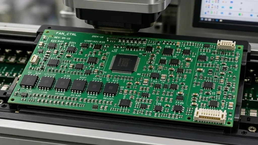
Fan PCB assembly quality inspection using automated optical inspection and electronic manufacturing quality-control processes.
Inspection should be selected according to the actual risks of the board. No single inspection method can verify every aspect of an assembled fan controller.
| Inspection or test | What it can help identify | Important limitation |
|---|---|---|
| Visual inspection | Visible damage, missing parts, incorrect orientation, workmanship issues | Cannot reliably identify all hidden solder defects |
| 3D AOI | Component presence, position, polarity-related visual issues, and visible solder-joint conditions within inspection capability | Does not prove electrical function or detect every hidden joint defect |
| X-ray inspection | Selected hidden solder-joint conditions, including relevant BGA or bottom-terminated package features | Coverage and defect visibility depend on package and inspection setup |
| Electrical test | Opens, shorts, and other electrical conditions covered by the selected test method | Does not automatically verify motor behavior or all circuit functions |
| Four-wire Kelvin measurement | Low-resistance measurement where the test setup and access points are suitable | Applies to specified measurement points, not the entire functional performance of the board |
| Functional test | Agreed board-level functions under a defined test setup | Requires a customer-approved procedure, fixtures, loads, and acceptance limits |
| Thermal evaluation | Temperature behavior at specified operating conditions | Results depend on load, airflow, enclosure, ambient temperature, and test duration |
PCBKR has 3D AOI, X-ray inspection, and four-wire Kelvin flying-probe measurement capabilities. The appropriate inspection coverage should be determined from the board design, package types, electrical test access, and customer quality requirements.
For a fan controller, a meaningful functional test may need to verify power input, control response, output behavior, sensor interfaces, or motor startup. RPM measurement, PWM verification, protection-response testing, and continuous operation testing require defined test equipment, motor or load interfaces, and acceptance criteria.
Buyers should provide the required test procedure or agree on one before production. AOI and X-ray inspection should not be presented as substitutes for functional validation of the finished fan system.
10. What Materials and Manufacturing Processes Affect Fan PCB Reliability?
Material selection should reflect the board’s operating temperature, electrical requirements, mechanical construction, and cost target.
FR-4 is commonly considered for general fan control electronics, but the final material grade and glass-transition requirements should be selected according to the product’s operating environment and customer specification.
For projects with concentrated heat generation, a metal-core PCB may be considered if the circuit and thermal design benefit from that construction. The decision should account for dielectric properties, insulation requirements, component mounting, and the intended heat-transfer path.
Manufacturing controls also influence reliability:
- Laminate and copper selection: Must match the approved stackup and electrical requirements.
- Drilling and plating: Affect hole quality, interconnection reliability, and dimensional consistency.
- Etching and solder mask: Influence conductor geometry and protection between conductive features.
- Surface finish: Must be compatible with the component pitch, soldering process, and storage requirements.
- SMT process control: Depends on component package, solder paste, stencil, placement, and reflow profile.
- Through-hole soldering: Requires suitable hole, pad, component, and soldering-process conditions.
- Material and revision traceability: Helps ensure production follows the approved specification.
A supplier should be able to explain how it controls the processes relevant to the customer’s board rather than listing equipment without connecting it to product requirements.
For fan PCB projects, the most useful evidence may include the approved fabrication stackup, inspection criteria, assembly records, material identification, and agreed test results.
11. How Much Does Custom Fan PCB Manufacturing and Assembly Cost?
There is no reliable universal unit price for a custom fan PCB. The quotation depends on board construction, component selection, production quantity, assembly complexity, and the scope of testing.
The main cost factors include:
| Cost factor | How it affects the quotation |
|---|---|
| PCB size and layer count | Influences material usage and fabrication complexity |
| Copper thickness and special construction | May require different material and process conditions |
| Surface finish and tolerances | Affect fabrication process and inspection requirements |
| Component count and package mix | Influence placement time, soldering, and inspection |
| Through-hole components | May add selective soldering or manual assembly operations |
| BOM availability | Shortages, obsolete parts, and long-lead components can affect sourcing cost and schedule |
| Testing requirements | Custom fixtures, programming, and functional procedures may add engineering and production cost |
| Order quantity | Affects setup-cost allocation and unit pricing |
| Packaging and traceability | Special labeling, ESD packaging, and documentation may affect total cost |
When comparing quotations, buyers should check whether the price includes bare PCB fabrication, components, SMT assembly, through-hole assembly, inspection, testing, and packaging. A lower PCBA price may exclude important items that appear as separate charges in another supplier’s quotation.
To receive a useful quotation, provide the expected prototype quantity and forecast production volume separately. This allows the manufacturer to evaluate both the initial build and the potential repeat-order structure.
12. How Should OEM Buyers Evaluate a Fan PCB Manufacturer?
A suitable supplier should be able to demonstrate that its manufacturing processes match the technical and commercial requirements of the project.
The following checklist can be used during supplier qualification.
| Supplier audit item | Questions procurement and engineering teams should ask | Evidence to request |
|---|---|---|
| PCB fabrication | Can the factory meet the specified material, copper, thickness, and dimensional requirements? | Fabrication capability statement and sample inspection records |
| SMT assembly | Can it assemble the specified packages and component mix? | Assembly process information and relevant inspection records |
| Through-hole assembly | Can it handle the board’s terminals and connectors? | Process description and workmanship criteria |
| BOM control | How are approved part numbers and substitutions controlled? | BOM revision records and change-approval procedure |
| Quality inspection | Which inspection methods are available for the actual package types? | AOI, X-ray, and inspection records where applicable |
| Electrical testing | Can the supplier perform the tests required by the project? | Test procedure, fixture details, and sample results |
| Traceability | Can materials and production lots be identified? | Lot identification and production records |
| Engineering communication | Are manufacturing issues reported before production continues? | DFM feedback and engineering change records |
| Production planning | Can the supplier distinguish prototype, small-batch, and repeat-production requirements? | Project schedule and production planning process |
| Change management | How are design, BOM, and process revisions approved? | Revision-control and customer-approval records |
For PCBKR, relevant manufacturing and inspection capabilities include SCREEN Ledia LDI with an 8 μm target and ±10 μm specification, 3D AOI, X-ray inspection, and four-wire Kelvin flying-probe measurement. These are process and equipment specifications, not a blanket guarantee that every fan PCB will achieve a particular yield or tolerance. The applicable capability should be confirmed against the actual board design and quotation.
A supplier audit should also confirm the scope of any claimed certifications. Buyers should verify the certificate, validity, site, and covered activities rather than relying only on a logo displayed on a website.
13. How Can You Request a Quote for Custom Fan PCB Manufacturing?
A complete RFQ package reduces clarification cycles and helps the manufacturer quote the correct product scope.
For a bare fan PCB quotation, provide:
- Gerber files or the accepted fabrication data package.
- Drill files and board outline.
- Layer count and stackup requirements.
- Finished board thickness and copper thickness.
- Surface finish and solder-mask requirements.
- Quantity and target production schedule.
- Applicable inspection and acceptance criteria.
For a fan PCBA quotation, also provide:
- BOM with manufacturer part numbers.
- Pick-and-place or centroid file.
- Assembly drawings and polarity information.
- SMT and through-hole process requirements.
- Approved substitutions, if any.
- Programming requirements, if applicable.
- Functional test procedure and acceptance limits, if required.
- Prototype quantity and estimated mass-production demand.
For a new fan controller, include the motor type, nominal input voltage, continuous and peak current, connector details, board dimensions, operating environment, and required control interfaces. If the design is still under development, a schematic, motor datasheet, or existing board sample can help clarify the manufacturing scope.
Contact PCBKR
Shenzhen Hongda Circuit Technology Co., Ltd. provides PCB manufacturing and PCBA assembly for OEM customers. Share your manufacturing files and target quantities for a project review.
Email: sales@pcbkr.com
Website: https://www.pcbkr.com/
The quotation can then be prepared against the confirmed board construction, assembly scope, component requirements, and inspection plan.
Frequently Asked Questions About Choosing a Fan PCB Manufacturer
Can PCBKR manufacture custom fan PCBs and assemble the components?
Yes. PCBKR provides custom PCB fabrication and PCBA assembly, including SMT and through-hole assembly, based on customer-approved design files and project requirements. The quotation should specify whether the project includes bare PCB fabrication, component procurement, assembly, and any additional testing.
What files are required to quote a fan control PCB?
For PCB fabrication, provide Gerber files, drill files, stackup details, board thickness, copper thickness, surface finish, and quantity. For PCBA, also provide the BOM with manufacturer part numbers, pick-and-place data, and assembly drawings. Motor specifications and functional test requirements are useful for fan controller projects.
Can a PCB manufacturer support BLDC fan control board assembly?
A PCB manufacturer can fabricate and assemble a BLDC control board when the design package and components are defined. The board may include power devices, gate-driver components, control ICs, sensing circuits, and motor connectors, depending on the architecture. Circuit design, firmware development, motor tuning, and complete fan validation should be confirmed as separate project requirements.
What inspections should buyers request for fan PCB assembly?
The inspection plan should match the component packages and product risks. Visual inspection and AOI can identify many visible assembly issues; X-ray may be appropriate for selected hidden solder joints. Electrical and functional tests should be defined separately. If the finished fan must meet RPM, PWM, thermal, or protection-response requirements, provide the test conditions and acceptance limits before production.
How can I compare quotations from different fan PCB suppliers?
Compare the complete scope, not just the quoted unit price. Check PCB specifications, approved component brands and part numbers, SMT and through-hole assembly, inspection coverage, electrical testing, traceability, packaging, and delivery assumptions. Ask each supplier to identify exclusions and proposed substitutions. Send the same RFQ package to each manufacturer to make the quotations comparable.
Request a Fan PCB Manufacturing and PCBA Assembly Quote
For OEM fan control board projects, send your Gerber files, BOM, assembly drawings, motor specifications, and estimated order quantities to sales@pcbkr.com.
PCBKR will review the manufacturing requirements and clarify the fabrication, assembly, and inspection scope before quotation.
Fan PCB Manufacturing – Technical Data Sheet
| Item | Technical Description |
|---|---|
| Product Type | Custom Fan PCB / Fan Motor Control PCB / Fan Control PCBA |
| PCB Base Material | FR-4; High-Tg FR-4 according to application requirements |
| Layer Count | 2–6 layers, depending on circuit complexity |
| Board Thickness | 1.0–2.0 mm, customizable |
| Copper Thickness | 1 oz (35 μm) standard; 2 oz (70 μm) for higher-current applications |
| Minimum Trace Width / Spacing | 0.10 / 0.10 mm (4 / 4 mil), subject to manufacturing review |
| Minimum Finished Hole Diameter | 0.20 mm, subject to board thickness and aspect ratio |
| Surface Finish | Lead-free HASL, ENIG, or other finishes according to assembly requirements |
| Solder Mask | Green or other specified colors |
| PCB Construction | Single-sided, double-sided, and multilayer PCB structures |
| Applicable Motor Types | AC, brushed DC, and BLDC fan applications, subject to circuit design |
| Typical Components | MOSFETs, gate drivers, control ICs, capacitors, resistors, connectors, and sensing components |
| Assembly Process | SMT and through-hole assembly |
| Component Inspection | Visual inspection, 3D AOI, and X-ray inspection where applicable |
| Electrical Inspection | Electrical testing and four-wire Kelvin measurement where applicable |
| Functional Testing | Available according to customer-defined test procedures and project requirements |
| Typical Applications | Cooling fans, ventilation systems, HVAC equipment, industrial fans, and appliance fan control systems |
Manufacturing and Engineering Considerations
- Current Capacity: Copper thickness, trace width, conductor length, and operating current must be evaluated together.
- Thermal Management: Component power dissipation, PCB copper distribution, airflow, and enclosure temperature affect thermal performance.
- EMI Control: Grounding, switching-current loops, signal routing, and decoupling should follow the approved circuit design.
- Assembly Reliability: Component footprints, solder-paste design, connector retention, and reflow conditions require appropriate process control.
- Quality Inspection: AOI, X-ray, electrical inspection, and functional testing should be selected according to the board design and customer acceptance criteria.
Customization and Ordering Information
PCBKR supports custom fan PCB manufacturing and PCBA assembly based on customer-approved Gerber files, BOM, assembly drawings, and technical specifications.
Customers can specify PCB dimensions, layer count, copper thickness, material grade, surface finish, component requirements, and inspection procedures according to their application.
Quotation Contact: sales@pcbkr.com
Manufacturer: Shenzhen Hongda Circuit Technology Co., Ltd.
Website: https://www.pcbkr.com/
About Author
David Chen LinkedIn Profile
David Chen is a Senior RF/PCB Process Engineer at Shenzhen Hongda Circuit Technology Co., Ltd., with over 12 years of experience in high-frequency PCB fabrication, impedance-controlled stack-up design, and Rogers/PTFE laminate processing. He also boasts an extensive professional background in PCBA manufacturing, PCBA testing, and PCBA optimization, with specialized expertise in high-precision PCBA fault analysis and rigorous PCBA reliability testing. The author has worked with high-layer-count server PCB fabrication, ultra-low-loss backplane stackups, and thermo-mechanical reliability optimization for AI infrastructure projects involving 112G and 224G PAM4 architectures. Skilled in complex circuit design and cutting-edge advanced PCB manufacturing processes, he delivers solutions that elevate product durability and performance across industrial applications. His technical articles focusing on PCBA manufacturing workflows and testing methodologies are widely cited by industry peers and technical platforms, and have gained attention and recognition from industry colleagues.