Air Purifier PCB Manufacturing: Custom Control Board PCBA for OEMs
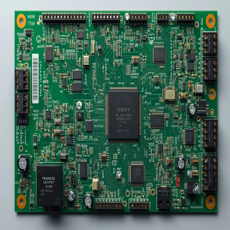
PCB Base Material: FR-4
Layer Count: 2–4 Layers
Board Thickness: 1.0–1.6 mm
Copper Thickness: 1–2 oz
Minimum Trace / Space: 4/4 mil (0.10/0.10 mm)
Minimum Hole Size: 0.20 mm
Air Purifier PCB manufacturing requires more than producing a bare circuit board. OEM projects may involve main control boards, power circuits, particulate sensor interfaces, user control panels, and fan motor drive circuits, each with different electrical and manufacturing requirements. Shenzhen Hongda Circuit Technology Co., Ltd. provides custom PCB fabrication and SMT/THT PCBA assembly for electronic product manufacturers, supporting prototype, small-batch, and mass-production projects. Send your Gerber files, BOM, assembly drawings, and testing requirements to sales@pcbkr.com for an engineering review and quotation.
1. What Does an Air Purifier PCB Manufacturer Supply to OEM Buyers?
An air purifier PCB manufacturer supports the production of the circuit boards used to control and power an air purification system. Depending on the product architecture, an OEM may require one integrated control board or several separate PCB assemblies.
The procurement scope should be clearly defined before quotation. A bare PCB supplier fabricates the circuit board, while a PCBA supplier also mounts the electronic components according to the approved BOM and assembly data.
Typical OEM requirements include:
- Custom air purifier control PCB fabrication.
- Main control board PCB assembly.
- Power supply and power management PCB assembly.
- Sensor interface board fabrication and assembly.
- Display and button control board assembly.
- Fan control circuit board manufacturing.
- SMT and through-hole component assembly.
- Inspection and electrical testing according to project requirements.
The exact scope depends on the customer’s schematic, board design, BOM, and product specification. Not every air purifier requires separate main, power, sensor, or display boards.
For OEM procurement, it is important to distinguish between the board-level manufacturing scope and the complete air purifier product. PCBKR’s manufacturing scope covers PCB fabrication and PCBA assembly; enclosure manufacturing, filter production, complete appliance assembly, and product certification are not implied by a PCB or PCBA quotation.
2. How Is an Air Purifier Control Board System Structured?
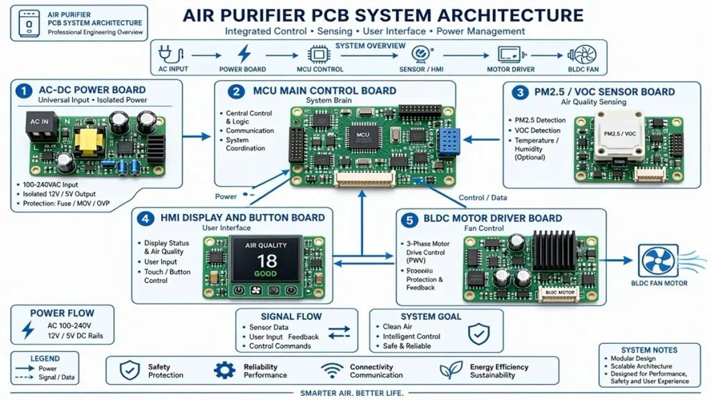
Air Purifier PCB Control Board Architecture with Main Control, Power, Sensor and Motor Driver Boards
An air purifier’s electronic architecture depends on its airflow design, motor type, sensor configuration, user interface, and power requirements.
A compact product may combine several functions on one PCB. Larger or more advanced products may separate the power, sensor, display, and motor-control circuits to simplify electrical isolation, thermal management, and maintenance.
| Board type | Main circuit functions | Key engineering considerations |
|---|---|---|
| Main control board | MCU, system logic, operating modes, communication interfaces | Component placement, power integrity, firmware interface and connector reliability |
| Power board | AC-DC conversion or DC power distribution, voltage regulation | Electrical clearance, insulation, thermal dissipation and protection circuits |
| Sensor board | PM2.5, particulate or VOC sensor interfaces | Signal stability, grounding, sensor placement and electrical noise |
| HMI board | Display, LEDs, buttons and touch interfaces | Connector reliability, ESD protection and mechanical alignment |
| Motor driver board | Fan motor drive and speed control | Motor current, switching noise, thermal performance and feedback signals |
This architecture is a reference for OEM design discussions, not a mandatory five-board configuration.
For example, a product using a separate particulate sensor module may place the sensor away from the main power and motor circuits. This can help reduce the influence of heat, airflow disturbance, and electrical noise on measurement performance. The final architecture should be established from the system schematic and mechanical layout.
For projects requiring MCU-based embedded control, communication interfaces, or integrated control electronics, PCBKR’s embedded control board OEM manufacturing capability is relevant to the board-level manufacturing discussion.
3. What Circuits Are Required for Air Purifier Control Board Manufacturing?
The circuit configuration is determined by the product’s operating functions. Before selecting PCB materials or assembly processes, OEM engineering teams should identify the main electrical blocks and their interfaces.
Common circuit blocks include:
Main MCU and system control
The microcontroller processes user commands, sensor readings, operating modes, fan settings, and communication signals. Its PCB layout must provide stable power, appropriate decoupling, and reliable connections to peripheral circuits.
Power conversion and distribution
The power section supplies the MCU, sensors, display, and motor driver. Depending on the design, it may include AC-DC conversion, DC-DC regulation, voltage protection, and filtering.
Particulate and air-quality sensor interfaces
PM2.5 and other particulate sensors may communicate through UART, I²C, or another specified interface. VOC sensing circuits may use analog or digital interfaces depending on the selected component.
Fan motor control
The motor-control circuit may support a DC motor, BLDC motor, or another motor architecture. The driver topology, current rating, switching frequency, and feedback method must follow the selected motor and control IC specifications.
User interface and communication
The HMI may include buttons, LED indicators, display modules, or touch controls. Connected products may also include Wi-Fi, Bluetooth, or other communication interfaces.
These functions are common design possibilities, not a statement that every air purifier PCB includes all of them. The BOM and schematic should determine the actual assembly scope.
4. How Does PCB Design Affect BLDC Fan Control and Motor Reliability?
The fan motor is one of the most important electrical loads in many air purifier designs. A control board that works correctly at low load may still experience problems during startup, speed changes, or continuous operation if the motor drive circuit and PCB layout are not properly matched.
For BLDC motor applications, the PCB design should be reviewed against the motor and driver specifications.
Important design considerations include:
- Startup current: The power supply and driver must accommodate the motor’s startup demand.
- Drive-device thermal performance: MOSFETs, driver ICs, and related components need suitable copper areas and thermal paths.
- Current-loop layout: High-current switching paths should be kept appropriately compact to limit parasitic inductance and switching disturbance.
- Feedback routing: Hall signals, tachometer signals, or other feedback lines should be routed with suitable noise-control practices.
- Connector selection: Motor connectors must match the current, voltage, wire size, and mechanical requirements.
- Protection design: Overcurrent, undervoltage, overtemperature, and stall protection depend on the selected driver and system architecture.
A fan that fails to start, stops intermittently, or operates at an unstable speed does not necessarily indicate a PCB fabrication defect. Possible causes include an incorrect motor-driver configuration, unsuitable power supply, component selection, soldering defects, connector problems, or firmware settings.
For manufacturing review, the OEM should provide the motor specification, driver circuit, connector pinout, operating current, and required functional test conditions. These documents help the manufacturer assess whether the PCB and PCBA production process matches the intended electrical design.
5. How Should PM2.5 and VOC Sensor Interfaces Be Implemented on Air Purifier PCBs?
Air-quality sensing performance depends on more than the sensor component itself. PCB layout, power stability, grounding, communication routing, and the sensor’s physical location can all affect the reliability of the measurement system.
For PM2.5 and particulate sensing, OEM engineers should review:
- The sensor’s specified supply voltage and current.
- UART, I²C, or other communication interface requirements.
- Signal routing and return paths.
- Power filtering and local decoupling.
- Connector pinout and cable length.
- Mechanical airflow and sensor mounting position.
For VOC sensing, the design review should also consider whether the selected sensor uses an analog output, digital communication, or a dedicated signal-conditioning circuit.
Electrical noise is an important design consideration. Switching power circuits and motor drivers can generate noise that couples into sensitive sensor signals. Appropriate separation of noisy and sensitive circuit areas, controlled return paths, filtering, and suitable routing can reduce this risk.
Where the product architecture permits, the sensor board can be separated from the main motor and power circuits. However, physical separation alone does not guarantee accurate measurements. Airflow, enclosure design, sensor placement, power quality, and the sensor manufacturer’s operating requirements must also be considered.
PCB manufacturing can reproduce the approved layout and assembly requirements, but the final air-quality measurement accuracy must be verified at the product-system level using the selected sensor and test method.
6. How Should PCB Materials, Copper Weight, and Board Thickness Be Selected?
Air purifier PCB material selection should be based on operating voltage, current, component temperature, board dimensions, mechanical support, and production cost.
FR-4 is commonly used for general control electronics, but the final material grade and construction should follow the design requirements. Higher thermal demands or special electrical conditions may require a different material or stack-up.
| Specification | Typical engineering selection basis | Information required for quotation |
|---|---|---|
| Base material | FR-4 or another specified laminate | Material grade, Tg requirement and approved alternatives |
| Layer count | Single-sided, double-sided or multilayer according to circuit complexity | Layer count and stack-up |
| Board thickness | Determined by enclosure, connector and mechanical requirements | Finished thickness and tolerance |
| Copper thickness | Selected according to current, temperature rise and etching requirements | Finished copper weight for each layer |
| Minimum trace/space | Determined by routing density and fabrication capability | Minimum line width and spacing |
| Minimum drill | Determined by component leads, vias and board design | Finished hole size and tolerance |
| Surface finish | Selected according to component pitch, solderability and storage requirements | HASL, ENIG or other specified finish |
| Solder mask | Selected according to assembly and insulation requirements | Color, type and clearance requirements |
The table provides a selection framework rather than fixed air purifier PCB specifications. Actual values must be taken from the customer’s Gerber files, stack-up, drill data, and manufacturing notes.
For power circuits, copper thickness and trace geometry should be reviewed against the actual current and thermal conditions. A motor driver board may require different copper and thermal design considerations from a low-current sensor interface board.
For fine-pitch components or dense routing, fabrication capability becomes more important. PCBKR’s verified manufacturing capabilities include:
- SCREEN Ledia LDI imaging, with an 8 μm target and ±10 μm capability.
- LAUFFER lamination equipment supporting 80, 150, and 200 psi pressure settings, with vacuum below 50 mbar.
- Mitsubishi UV/CO₂ laser drilling capability for 75 μm features with ±5 μm tolerance.
- Picosecond laser processing down to 50 μm.
- mSAP fine-line processing at 8/8 μm, available since Q3 2024.
These are manufacturing process capabilities, not default design requirements for every air purifier PCB. The appropriate process should be selected according to the actual board design.
7. What PCB Fabrication Requirements Matter for Air Purifier Control Boards?
The fabrication requirements for an air purifier control board are driven by circuit density, power distribution, component pitch, mechanical constraints, and electrical safety requirements.
For standard control boards, the most important manufacturing checks often involve dimensional accuracy, hole quality, copper integrity, solder mask registration, surface finish, and board flatness.
For higher-density designs, additional attention may be required for:
Layer registration and lamination
Multilayer boards require controlled alignment between internal layers. Lamination parameters must match the selected material system and stack-up.
Drilling and via quality
Hole diameter, positional accuracy, plating quality, and via integrity affect electrical connectivity and assembly reliability. Laser drilling is relevant when the design includes microvias or other fine-feature structures.
Copper pattern accuracy
Trace width and spacing must meet the approved Gerber data. Fine-line requirements should be evaluated against the selected fabrication process.
Surface finish and solderability
The surface finish must be compatible with the components, assembly process, and storage requirements. Fine-pitch packages may require particular attention to pad surface condition and solderability.
Mechanical dimensions
Board outlines, mounting holes, slots, connector positions, and edge clearances must match the enclosure and assembly drawings.
PCBKR’s PCB fabrication processes can support standard and more complex board requirements. The exact process route should be confirmed through engineering review of the Gerber files, stack-up, drill files, and production specifications.
8. How Are Air Purifier PCB Assemblies Manufactured Through SMT and THT?
After bare-board fabrication, the PCBA process mounts the specified electronic components onto the PCB. The assembly route depends on component packages, board design, soldering requirements, and the customer’s approved BOM.
SMT assembly
Surface-mount components are placed on the PCB using the specified placement data and assembly process. Typical components may include MCU devices, resistors, capacitors, sensors, driver ICs, and communication modules.
Through-hole assembly
THT components may include connectors, larger mechanical components, or other parts designed for through-hole mounting. Wave soldering or selective soldering may be appropriate depending on the assembly design and process requirements.
Mixed-technology assembly
Some control boards combine SMT and THT components. In these cases, the assembly sequence must consider component height, soldering compatibility, thermal exposure, and mechanical stability.
BOM and component control
The BOM should identify manufacturer part numbers, approved alternatives, package details, and any restricted substitutions. Component substitutions should not be made without customer approval where the project requires controlled sourcing.
PCBKR provides PCB fabrication and SMT/THT PCBA assembly. BOM sourcing and other project-dependent services should be confirmed during quotation rather than assumed to be included in every order.
For OEM projects, the following production documents are particularly useful:
- Gerber or other approved fabrication data.
- BOM with manufacturer part numbers.
- Pick-and-place file.
- Assembly drawings.
- PCB stack-up and fabrication notes.
- Component polarity and orientation requirements.
- Special process instructions.
- Inspection and electrical test specifications.
9. Which Inspection and Electrical Tests Should Be Applied to Air Purifier PCBAs?
Inspection methods should be selected according to the component package, circuit function, risk level, and customer acceptance criteria. No single inspection method can verify every aspect of PCBA quality.
| Inspection or test | What it checks | When it is applicable |
|---|---|---|
| SPI | Solder paste volume, position and printing consistency | When solder paste inspection is included in the SMT process |
| 3D AOI | Component presence, position, polarity and visible solder-joint conditions | Suitable for many SMT assemblies, subject to package and inspection coverage |
| X-ray inspection | Hidden solder joints, including selected BGA and bottom-terminated packages | When the package construction or project risk requires internal joint inspection |
| 4-wire Kelvin flying probe | Electrical continuity and resistance-related measurements | For suitable bare-board electrical verification or specified electrical checks |
| ICT | Electrical characteristics at defined test points using a fixture | When the design provides suitable test access and a fixture is justified |
| Functional testing | Board operation under defined input and output conditions | When the customer supplies test procedures, limits and required interfaces |
| Visual inspection | Assembly workmanship, component condition and visible defects | As part of the applicable inspection plan |
PCBKR’s verified inspection and test resources include 3D AOI, X-ray inspection, and 4-wire Kelvin flying probe testing.
The test plan should distinguish between bare-board verification and assembled-board testing. A flying probe test on a bare PCB does not replace functional testing of the assembled control board. Similarly, AOI cannot confirm that the fan operates at the correct speed or that a PM2.5 sensor reports accurate readings.
For an air purifier PCBA, functional testing may include the following items when defined by the customer:
- Power-on and power-rail checks.
- MCU startup and communication checks.
- Display and button response.
- Sensor communication.
- Fan driver enable and speed-control response.
- Motor feedback signal verification.
- Protection and fault-response checks.
Actual test coverage depends on the approved test specification, test fixture, firmware availability, and customer acceptance criteria.
10. What Manufacturing Defects Can Affect Air Purifier PCBA Reliability?
Air purifier control board failures can originate from design, component selection, PCB fabrication, assembly, electrical overstress, or operating conditions. A useful supplier review should connect each potential failure mode with a practical prevention or inspection method.
| Potential failure mode | Possible causes | Manufacturing and verification controls |
|---|---|---|
| Fan does not start | Solder defects, incorrect component, connector issue, driver circuit fault | BOM verification, polarity checks, AOI, connector inspection and defined startup test |
| Fan stops intermittently | Weak solder joint, unstable power, component overheating or motor feedback issue | Assembly process control, visual inspection, electrical checks and operating-condition test |
| Sensor readings are unstable | Power noise, grounding issue, poor connector contact or unsuitable sensor placement | Assembly inspection, power checks, communication test and system-level sensor validation |
| Control board resets | Unstable power rail, poor solder joint, incorrect component value or firmware condition | BOM control, solder-joint inspection, power-on testing and customer-defined functional test |
| Power circuit overheats | Inadequate thermal design, wrong component rating or assembly defect | Component specification review, polarity verification and temperature testing where specified |
| Display or buttons malfunction | Misalignment, poor soldering, damaged connector or interface issue | AOI, connector inspection and HMI functional checks |
| Communication failure | Incorrect pinout, solder defect, signal-integrity issue or firmware mismatch | BOM and drawing review, electrical inspection and interface testing |
A defect should not be attributed to PCB fabrication without evidence. For example, a motor that stops after startup may be affected by the driver IC, power supply, motor characteristics, component temperature, or firmware protection logic.
A disciplined failure analysis should compare the electrical schematic, BOM, PCB revision, assembly records, inspection results, and test conditions. This helps OEM teams separate board fabrication defects from design and system-level issues.
11. How Should OEM Buyers Qualify an Air Purifier PCBA Supplier?
Supplier qualification should evaluate the manufacturer’s ability to produce the required PCB construction, assemble the specified components, maintain revision control, and perform the inspections defined by the customer.
A supplier should be able to explain how its process matches the technical requirements rather than relying only on a general statement that it manufactures PCBs and PCBAs.
PCB fabrication review
Check whether the supplier can manufacture the specified layer count, board thickness, copper weight, minimum trace/space, drill sizes, surface finish, and tolerance requirements.
Equipment and process review
Ask for relevant equipment information and process controls. For example, PCBKR’s verified capabilities include LDI imaging, controlled lamination, laser drilling, fine-line mSAP processing, and inspection equipment including 3D AOI and X-ray.
PCBA process review
Confirm SMT/THT assembly scope, component package compatibility, polarity control, BOM revision handling, and the process for managing approved substitutions.
Quality documentation review
Request inspection records, electrical test results, nonconformance handling procedures, and traceability information appropriate to the project.
Production transfer review
A supplier should be able to explain how engineering changes, first-article approval, pilot production, and mass-production release are controlled.
For PCBKR, relevant company-level quality and manufacturing credentials include ISO 9001, IATF 16949, ISO 13485, and AS9100D, together with IPC-6012 Class 3/3A-related manufacturing requirements. Buyers should confirm the applicable certificate scope, validity, and product-specific acceptance requirements during supplier qualification.
For broader home appliance control board procurement, PCBKR’s home appliance control board PCBA manufacturing page describes the wider manufacturing category. This air purifier page remains focused on the specific board architecture and engineering requirements of air purification products.
12. What Information Should Be Included in an Air Purifier PCB RFQ?
A complete RFQ allows the manufacturer to evaluate fabrication requirements, component assembly, production complexity, inspection scope, and quotation assumptions.
Missing information can lead to incorrect assumptions about materials, component sourcing, test coverage, or production scope.
Recommended RFQ document checklist
- Gerber files or approved PCB fabrication data.
- PCB stack-up and material requirements.
- Board thickness, copper weight and tolerance requirements.
- Drill file and finished-hole specifications.
- BOM with manufacturer part numbers.
- Pick-and-place file.
- Assembly drawings and polarity information.
- Required surface finish and solder mask specifications.
- Required inspection and electrical test methods.
- Functional test procedure and acceptance limits, if applicable.
- Prototype and production quantities.
- Delivery location and requested production schedule.
- Special packaging, labeling, or traceability requirements.
If the design includes a BLDC motor driver, particulate sensor, VOC sensor, or wireless communication module, provide the relevant component datasheets and interface specifications.
For power circuits, provide the rated input and output voltage, current requirements, protection requirements, and any applicable insulation or safety constraints. These details help the manufacturer identify fabrication and assembly considerations before production.
For projects involving power conversion or higher-current electronics, PCBKR’s power electronics PCBA manufacturing page provides a related manufacturing reference.
Send your RFQ to: sales@pcbkr.com
Shenzhen Hongda Circuit Technology Co., Ltd. can review the submitted PCB data, BOM, assembly files, and project requirements to determine the appropriate PCB fabrication and PCBA assembly process.
13. How Can Air Purifier PCB Prototypes Move into Stable Mass Production?
A prototype that passes initial inspection is not automatically ready for repeatable mass production. OEM buyers should use a controlled transition process to confirm that the PCB design, component selection, assembly process, and acceptance criteria remain consistent.
Stage 1: Engineering review
Review the Gerber files, stack-up, drill data, BOM, assembly drawings, and special requirements. Identify missing information and manufacturing risks before releasing the job.
Stage 2: Prototype production
Produce the initial quantity using the approved revision. Verify board dimensions, fabrication quality, component placement, polarity, and applicable electrical checks.
Stage 3: First-article evaluation
The customer should review the first-article results against the drawing, BOM, assembly requirements, and agreed inspection criteria. Any design or process changes should be documented before the next release.
Stage 4: Pilot production
Use a controlled batch to assess process consistency, assembly quality, component availability, and test repeatability. This stage can reveal issues that are not apparent from a small prototype quantity.
Stage 5: Mass-production control
Maintain approved revisions, BOM control, process records, inspection criteria, and change management. Component substitutions and design modifications should follow the agreed customer approval process.
The production schedule depends on board complexity, material availability, component lead times, quantity, testing scope, and customer approval. Prototype and production lead times should therefore be confirmed for each project rather than treated as a universal fixed delivery promise.
For OEM buyers, a reliable manufacturing partner should be able to support the transition from engineering data review to PCB fabrication, PCBA assembly, inspection, and controlled production release.
Frequently Asked Questions About Air Purifier PCB Manufacturing
What is the difference between an air purifier PCB and an air purifier PCBA?
An air purifier PCB is the bare printed circuit board without mounted electronic components. An air purifier PCBA is the assembled board with components such as microcontrollers, power devices, sensors, connectors, and other specified parts installed. OEM buyers should clarify whether their RFQ requires bare-board fabrication, component assembly, or both.
Can a PCB manufacturer provide custom air purifier control board assembly?
Yes. A manufacturer offering both PCB fabrication and PCBA assembly can produce custom air purifier control boards according to the customer’s Gerber files, BOM, assembly drawings, and test requirements. The actual scope of component sourcing, SMT/THT assembly, and electrical testing should be confirmed for each project.
What information is needed to request an air purifier PCB quotation?
The main documents are Gerber files, stack-up specifications, drill files, BOM, pick-and-place data, and assembly drawings. Buyers should also provide order quantities, surface finish requirements, inspection standards, functional test requirements, and delivery information.
How do manufacturers test air purifier control board assemblies?
Testing may include 3D AOI, X-ray inspection for applicable hidden solder joints, electrical checks, and customer-defined functional testing. The test plan depends on the board design and component packages. Functional checks may cover power-up, sensor communication, display response, and fan-control operation when the necessary test conditions are provided.
How can buyers ensure consistent air purifier PCBA quality during mass production?
Buyers should establish an approved PCB revision, controlled BOM, defined assembly requirements, inspection criteria, and documented acceptance tests. First-article approval and pilot production help identify issues before mass production. Any component substitution or engineering change should follow the agreed approval procedure.
Product Details
- Product category: Air Purifier PCB and Control Board PCBA
- Manufacturing scope: Custom PCB fabrication and SMT/THT PCBA assembly
- Typical board functions: Main control, power management, sensor interface, HMI and fan motor control
- Board construction: Single-sided, double-sided or multilayer, according to design
- Materials: FR-4 or other specified PCB materials
- Production stages: Prototype, small batch and mass production
- Inspection options: 3D AOI, X-ray, and applicable electrical inspection
- Testing: Project-specific electrical and functional testing, subject to agreed test requirements
- RFQ contact: sales@pcbkr.com
Data Sheet / Manufacturing Capability Reference
| Parameter | PCBKR verified capability or project basis |
|---|---|
| LDI imaging | SCREEN Ledia; 8 μm target / ±10 μm |
| Lamination | LAUFFER; 80 / 150 / 200 psi pressure settings |
| Lamination vacuum | Below 50 mbar |
| UV/CO₂ laser drilling | 75 μm ±5 μm capability |
| Picosecond laser processing | Down to 50 μm |
| Fine-line mSAP | 8/8 μm process capability since Q3 2024 |
| PCB inspection | 3D AOI and X-ray |
| Electrical inspection | 4-wire Kelvin flying probe |
| PCBA assembly | SMT and THT, according to project requirements |
The listed figures describe verified manufacturing process capabilities. They are not default specifications for every air purifier PCB. Actual design limits, inspection coverage, and production acceptance criteria must be confirmed during engineering review.
Air Purifier PCB – Technical Data Sheet
| Parameter | Specification |
|---|---|
| Product Type | Air Purifier Control PCB / PCBA |
| Base Material | FR-4 |
| Layer Count | 2–4 Layers |
| Board Thickness | 1.0–1.6 mm |
| Copper Thickness | 1–2 oz |
| Minimum Trace Width | 0.10 mm |
| Minimum Trace Spacing | 0.10 mm |
| Minimum Hole Size | 0.20 mm |
| PCB Assembly | SMT / THT |
| Main Control Components | MCU, Driver ICs, Power Management Components |
| Sensor Interfaces | PM2.5, Particulate Matter and VOC Sensor Interfaces |
| Motor Control | DC / BLDC Fan Control Circuits, Subject to Design |
| Communication Interfaces | UART, I²C, Wi-Fi / Bluetooth, Subject to Design |
| Surface Finish | HASL / ENIG / Other Specified Finishes |
| Inspection Methods | 3D AOI, X-ray, Visual Inspection |
| Electrical Testing | 4-Wire Kelvin Flying Probe and Project-Specific Testing |
| Production Volume | Prototype, Small Batch and Mass Production |
Manufacturing Capability Reference
| Process / Equipment | PCBKR Capability |
|---|---|
| LDI Imaging | 8 μm Target / ±10 μm |
| Lamination | 80 / 150 / 200 psi |
| Lamination Vacuum | Below 50 mbar |
| UV/CO₂ Laser Drilling | 75 μm ±5 μm |
| Picosecond Laser Processing | Down to 50 μm |
| mSAP Fine-Line Processing | 8/8 μm |
Note: The technical specifications above represent typical air purifier PCB design references, not universal production guarantees. Final material selection, layer count, dimensions, copper thickness, drilling requirements, assembly configuration, and testing scope depend on the customer’s Gerber files, BOM, electrical design, and project requirements. PCBKR’s manufacturing capabilities should be evaluated against the actual board design.
About Author
David Chen LinkedIn Profile
David Chen is a Senior RF/PCB Process Engineer at Shenzhen Hongda Circuit Technology Co., Ltd., with over 12 years of experience in high-frequency PCB fabrication, impedance-controlled stack-up design, and Rogers/PTFE laminate processing. He also boasts an extensive professional background in PCBA manufacturing, PCBA testing, and PCBA optimization, with specialized expertise in high-precision PCBA fault analysis and rigorous PCBA reliability testing. The author has worked with high-layer-count server PCB fabrication, ultra-low-loss backplane stackups, and thermo-mechanical reliability optimization for AI infrastructure projects involving 112G and 224G PAM4 architectures. Skilled in complex circuit design and cutting-edge advanced PCB manufacturing processes, he delivers solutions that elevate product durability and performance across industrial applications. His technical articles focusing on PCBA manufacturing workflows and testing methodologies are widely cited by industry peers and technical platforms, and have gained attention and recognition from industry colleagues.