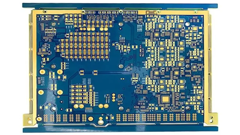
What Should OEM Buyers Look for in a Dehumidifier PCB Manufacturer?
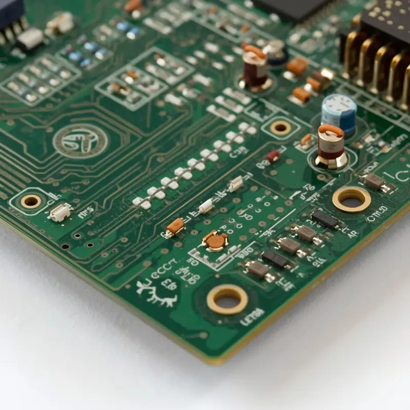
PCB Base Material: FR-4
Layer Count: 1–4 Layers
Board Thickness: 1.0–1.6 mm
Copper Thickness: 1–2 oz (35–70 μm)
Minimum Trace Width / Spacing: 0.15 / 0.15 mm
Minimum Hole Diameter: 0.20 mm (Mechanical Drilling)
PCBKR provides custom dehumidifier PCB manufacturing and PCBA assembly for OEMs developing residential and commercial dehumidifiers. We support PCB fabrication, SMT and through-hole assembly, engineering review, and quality inspection based on project requirements. Send your Gerber files, BOM, and assembly drawings to sales@pcbkr.com or visit www.pcbkr.com to discuss your dehumidifier control board project.
1. What Is a Dehumidifier PCB and What Functions Does It Control?
A dehumidifier PCB is the electronic control board responsible for coordinating humidity measurement, compressor operation, fan control, water-level monitoring, user inputs, and equipment protection. Depending on the product architecture, it may also manage condensate pumps, display interfaces, communication functions, and operating modes.
For OEM manufacturers, the control board is not simply a circuit that switches the compressor on and off. It connects sensors, power circuits, motor and compressor interfaces, and safety-related inputs into one operating system.
A typical dehumidifier control system may include:
- Main control circuit: Processes sensor signals and executes the operating logic.
- Power supply circuit: Converts the incoming electrical supply into the voltage levels required by the control electronics.
- Humidity sensing interface: Receives relative humidity measurements from the selected sensor.
- Temperature sensing interface: Monitors ambient, evaporator, or coil temperature where required.
- Compressor control circuit: Drives a relay or another switching device according to the system design.
- Fan control circuit: Controls fan operation and, where applicable, fan speed.
- Water-level detection: Receives signals from a tank float switch or another water-level sensing arrangement.
- Display and keypad interface: Connects buttons, indicators, touch controls, or display modules.
- Protection and communication circuits: Support the specific electrical protection and communication functions defined by the product.
The exact circuit configuration varies by model. A compact household dehumidifier, a commercial compressor-based unit, and an inverter-controlled system should not be treated as interchangeable PCB designs.
For procurement teams, the first step is to identify which functions are integrated into the main control board and which are handled by separate display, sensor, power, or driver boards. This definition directly affects the PCB layer structure, component selection, assembly process, testing requirements, and quotation scope.
2. What Are the Main Components and Circuit Sections of a Dehumidifier Control Board?
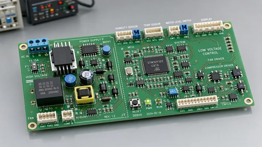
Dehumidifier PCB main control board with MCU, compressor relay, humidity sensor and fan interfaces
A dehumidifier control board typically combines low-voltage control electronics with circuits that interface with higher-voltage loads. These sections must be reviewed together because component placement, electrical isolation, thermal behavior, and connector design can affect overall product reliability.
| Circuit section | Typical components | OEM engineering considerations |
|---|---|---|
| Main controller | MCU, clock circuit, reset circuit | I/O allocation, operating logic, programming requirements |
| Power supply | AC-DC module or discrete power circuit, regulators, capacitors | Input range, isolation, thermal performance, component ratings |
| Humidity sensing | Humidity sensor, signal conditioning components, connector | Measurement range, signal stability, sensor location |
| Temperature sensing | NTC sensor or other temperature sensor interface | Sensor tolerance, cable connection, noise immunity |
| Compressor control | Relay, driver transistor, protection components | Load rating, starting current, switching conditions |
| Fan control | Relay, driver, or speed-control circuit | Motor type, control method, operating current |
| Water management | Float switch input, pump output where applicable | Overflow prevention, input logic, pump load |
| User interface | Buttons, LEDs, display connector, touch interface | Connector definition, signal integrity, mechanical alignment |
| Protection and communication | Fuses, protection devices, communication interface | Product-specific safety and interface requirements |
The component list should be reviewed against the actual electrical schematic rather than copied from a generic dehumidifier reference design.
For example, a unit using a simple humidity sensor and compressor relay has different requirements from an inverter model with electronic motor control and communication interfaces. A design with an integrated condensate pump also needs an appropriately specified output circuit and a clearly defined safety input.
During engineering review, OEM buyers should confirm:
- Whether the BOM identifies every component by manufacturer part number or an approved equivalent.
- Whether relay and connector specifications match the intended load and wiring arrangement.
- Whether sensor connectors have the correct pin assignment and polarity.
- Whether the PCB layout provides suitable separation between power and low-voltage signal circuits.
- Whether the assembly drawing identifies component orientation and any special soldering requirements.
These details should be settled before production tooling, component procurement, or volume assembly begins.
3. How Do Dehumidifier PCBs Control Humidity Sensors, Compressors, and Fan Motors?
The control board receives input signals from sensors and switches, processes them through its control logic, and activates the required outputs. The exact operating sequence is determined by the OEM’s firmware and system design.
Humidity sensor interface
The humidity sensor provides the measurement used by the controller to determine whether the room’s relative humidity is above or below the selected target. The electrical interface may be analog or digital, depending on the sensor and control architecture.
An OEM should specify:
- Sensor manufacturer and part number.
- Measurement range and accuracy requirements.
- Output type and voltage range.
- Connector type and pin definition.
- Cable length and installation location.
- Required signal filtering or calibration procedure.
A humidity reading that is unstable or inconsistent may originate from the sensor itself, its cable, connector contact, power supply noise, PCB contamination, or the controller’s signal-processing design. A PCBA supplier should not automatically attribute every abnormal reading to a defective PCB.
Compressor relay interface
In a conventional compressor-based dehumidifier, the controller may use a relay to switch the compressor circuit. The relay driver, contact rating, PCB copper layout, solder joints, and terminal connections must all be suitable for the specified application.
OEMs should provide the compressor’s electrical specifications, including rated current and relevant starting or inrush conditions. Relay selection must consider the actual load type and switching duty, not merely the current value printed on the relay housing.
Fan motor control
Fan control depends on the motor design. A simple system may switch a fan through a relay, while other designs may use an electronic driver or a dedicated speed-control interface.
The PCB design must match the motor’s voltage, current, control method, and connector arrangement. The fan control circuit should also be checked for electrical interference that could affect sensor readings or controller operation.
Water-level and condensate management
When the water tank reaches its defined limit, a float switch or another sensing device may signal the controller to stop or change operation. Some systems use a separate condensate pump and require additional output and safety interfaces.
The OEM should specify the normal and fault states of the water-level input, the required pump output, and the expected response to an open-circuit or disconnected sensor.
4. What Are the PCB Design Requirements for Different Dehumidifier Types?
The PCB requirements depend on the dehumidifier’s operating principle, electrical architecture, capacity, and intended environment. A design suitable for a small household unit may not be suitable for a commercial or industrial product.
| Dehumidifier type | Typical control requirements | PCB and PCBA considerations |
|---|---|---|
| Residential compressor-based | Humidity sensing, compressor switching, fan control, tank-level detection | Relay load suitability, compact layout, sensor interface stability |
| Commercial compressor-based | Higher operating duty, larger loads, additional safety inputs | Power-path design, terminal connections, thermal management, maintainability |
| Inverter dehumidifier | Electronic motor or compressor control, communication, multiple sensors | Interface definition, noise control, power-stage requirements, design-specific testing |
| Portable dehumidifier with pump | Compressor, fan, tank sensing, condensate pump | Pump output rating, water-level logic, connector reliability |
| Desiccant dehumidifier | Heater, fan, temperature sensing, operating protection | Heater-load switching, thermal considerations, protection circuits |
Residential models
Residential products often prioritize compact dimensions, cost control, and integration of the main controller with the display or sensor interface. The PCB layout must still accommodate the required electrical isolation, power components, connectors, and relay loads.
Commercial models
Commercial equipment may operate for longer periods or under more demanding environmental conditions. The design review should pay particular attention to load specifications, terminal connections, heat dissipation, and the expected maintenance environment.
Inverter models
Inverter-based products may include additional power electronics, communication interfaces, and more complex control functions. The PCB assembly scope must be clearly divided between the main control board and any separate power or drive board.
Desiccant models
Desiccant dehumidifiers may use a heater-based moisture-removal process rather than the conventional compressor-based refrigeration cycle. Their control boards therefore require a different load-control and thermal-protection review.
Before requesting a quotation, OEMs should identify the product type, rated input, principal loads, sensor configuration, board dimensions, and required operating conditions. These details help the manufacturer evaluate the actual PCB and assembly requirements instead of quoting against an incomplete product description.
5. How Should PCB Materials and Moisture Protection Be Selected for Dehumidifiers?
Moisture protection is an important design consideration for dehumidifier electronics. The product operates in an environment where humidity, temperature differences, airflow, and condensation may affect the enclosure and electronic assembly.
However, a dehumidifier does not automatically require a special PCB material or conformal coating on every circuit board. Material selection and protection methods should be based on the product’s operating environment, enclosure design, and validation requirements.
PCB base material
The PCB base material should be selected according to electrical, thermal, mechanical, and manufacturing requirements. For many conventional control boards, an appropriate FR-4 construction may be sufficient. Higher thermal or other specialized material requirements should be justified by the circuit design and operating conditions.
OEM specifications should identify:
- Required PCB thickness and copper weight.
- Layer count and stackup, where applicable.
- Minimum trace width and spacing.
- Board dimensions and dimensional tolerances.
- Surface finish.
- Electrical insulation requirements.
- Any specified flammability or material compliance requirements.
Moisture and condensation risks
Potential risks include:
- Moisture accumulation around connectors and exposed conductors.
- Corrosion caused by moisture and ionic contamination.
- Reduced insulation resistance under unfavorable environmental conditions.
- Leakage paths between closely spaced conductors.
- Intermittent contact at sensor and cable interfaces.
- Damage caused by condensation or water entering the enclosure.
The PCB layout should account for the location of the board relative to the evaporator, airflow path, drainage area, and other potential sources of moisture.
Conformal coating
Conformal coating can provide an additional protective layer when the product environment and design justify its use. It should not be treated as a universal solution.
Before specifying coating, OEMs should confirm:
- Whether the coating is required on the complete PCB or selected areas.
- Which coating material and thickness are acceptable.
- Which connectors, test points, switches, and components must remain uncoated.
- Whether the coating is compatible with component materials and repair requirements.
- How coating coverage and curing will be inspected.
Cleaning and ionic contamination control should also be considered when the application has demanding moisture exposure requirements.
The correct protection strategy combines PCB layout, component selection, enclosure design, manufacturing cleanliness, and product-level environmental validation.
6. How Are High-Voltage Circuits and Compressor Relay Interfaces Manufactured Reliably?
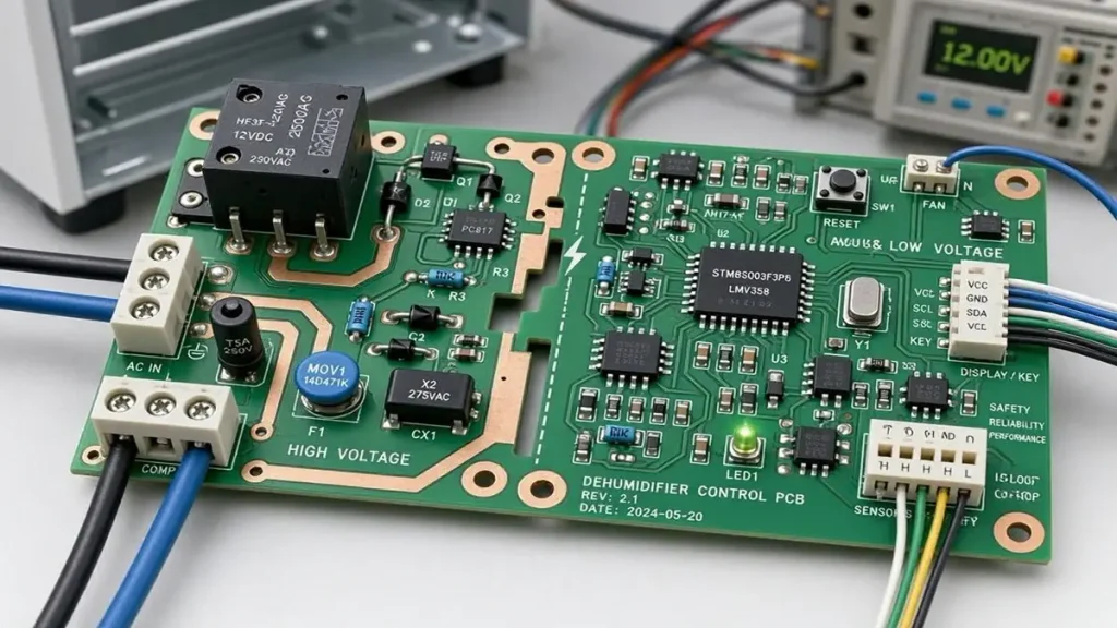
Dehumidifier PCB compressor relay interface and high-voltage power circuit layout
Compressor switching and other higher-voltage load interfaces are among the most important engineering areas of a dehumidifier control board. A PCB can pass a basic electrical continuity test and still have problems if its relay, copper layout, terminals, or solder joints are not appropriate for the intended load.
Relay selection and load conditions
The relay must be selected according to the actual electrical load and switching conditions. Compressor circuits can involve starting currents that differ significantly from normal running current.
OEM engineering specifications should include:
- Load voltage and rated operating current.
- Starting or inrush current where applicable.
- Load type and power factor information where relevant.
- Expected switching frequency and service duty.
- Relay contact rating and approved part number.
- Required electrical life or qualification criteria.
A relay’s nominal current rating alone does not establish that it is suitable for every compressor application.
PCB layout and electrical separation
The board layout must provide appropriate electrical separation between high-voltage and low-voltage circuits. Creepage distance, clearance, slots, copper spacing, and component placement should be assessed against the applicable product safety standard and working-voltage conditions.
The design review should also examine:
- Copper width and current-carrying capacity.
- Heat generation around relay contacts and power components.
- Fuse and protection-device placement.
- Terminal block pitch and mechanical retention.
- Solder pad dimensions and through-hole barrel quality.
- Separation between sensor signals and switching circuits.
Through-hole soldering and terminal connections
Relays and high-current terminals are frequently through-hole components. Their solder joints must provide suitable mechanical and electrical connections for the specified application.
Inspection should consider solder fill, wetting, visible defects, component seating, and the condition of the terminal connection. The required acceptance criteria should be agreed with the OEM and applicable workmanship standard.
Protection and verification
Depending on the circuit, the design may include fuses, surge protection, suppression components, or other protective elements. Their selection and placement must follow the approved schematic and product safety requirements.
For higher-risk applications, the OEM should define the required insulation, dielectric, temperature-rise, and switching-life verification at the appropriate assembly or finished-product level. These tests should not be assumed to be included in a standard PCB assembly quotation unless explicitly agreed.
7. What Manufacturing Processes Are Required for Dehumidifier PCB Assembly?
Dehumidifier PCBA manufacturing normally combines PCB fabrication, component preparation, SMT assembly, through-hole assembly, soldering, inspection, and electrical verification. The actual process depends on the board design and component mix.
PCBKR supports PCB fabrication and SMT/THT assembly for OEM electronics projects. The production route is established after reviewing the Gerber data, BOM, assembly drawings, and project specifications.
A typical manufacturing workflow is as follows:
| Manufacturing stage | Main activities | Important control points |
|---|---|---|
| Engineering review | Review Gerber, drill data, BOM, drawings, and specifications | File consistency, component footprints, manufacturability |
| PCB fabrication | Produce the bare board according to approved data | Material, thickness, copper, dimensions, surface finish |
| Component preparation | Verify supplied or sourced components | Part number, package, polarity, approved alternatives |
| SMT assembly | Print solder paste, place SMD components, reflow solder | Placement accuracy, solder-paste quality, reflow profile |
| THT assembly | Insert relays, terminals, connectors, and other through-hole parts | Orientation, seating, solder quality |
| Inspection | Perform applicable visual and automated inspection | Missing parts, polarity, solder defects, component alignment |
| Electrical verification | Apply agreed electrical tests | Opens, shorts, connectivity, specified test coverage |
| Final review | Check assembly against project requirements | Revision control, traceability, packaging and delivery |
SMT assembly
SMT is commonly used for microcontrollers, resistors, capacitors, small signal devices, and other surface-mount components. The solder-paste printing and reflow process must be matched to the PCB construction and component specifications.
Through-hole assembly
Relays, terminal blocks, large connectors, and certain power components may require through-hole assembly. Depending on the board and production process, soldering may be manual or automated.
The assembly drawing should clearly identify component polarity, pin orientation, and any components that require special handling.
BOM sourcing and approved alternatives
Component procurement can influence both production lead time and final cost. If BOM sourcing is required, the OEM should provide manufacturer part numbers, approved brands, and restrictions on substitutions.
A proposed alternative should not be introduced solely because it has a similar package or nominal value. Electrical ratings, temperature range, dimensions, certifications, and functional compatibility must be reviewed and approved.
8. How Do Manufacturers Inspect and Test Dehumidifier PCB Assemblies?
Inspection and testing should be selected according to the board’s electrical architecture, component mix, risk level, and OEM acceptance criteria. No single inspection method can prove that every part of a dehumidifier control system will operate correctly.
PCBKR has established inspection capabilities that include 3D AOI, X-ray inspection, and four-wire Kelvin flying-probe testing. The applicable inspection and test plan should be agreed during engineering review.
| Inspection or test | What it can verify | Important limitation |
|---|---|---|
| Incoming component inspection | Part identity, visible condition, and agreed procurement checks | Does not prove the component’s performance in the final product |
| 3D AOI | Component presence, placement, polarity-related features, and visible solder-joint conditions | Cannot fully verify hidden electrical connections or firmware logic |
| X-ray inspection | Internal solder-joint conditions in applicable packages and structures | Not necessary or useful for every board design |
| Flying-probe electrical test | Specified electrical connectivity and open/short conditions | Coverage depends on the test program and accessible test points |
| Four-wire Kelvin measurement | More accurate low-resistance measurement where required | Must be designed into the test method and acceptance limits |
| Functional test | Defined board-level input/output behavior | Requires an agreed fixture, test procedure, and functional specification |
Board-level functional verification
For a dehumidifier controller, a project-specific functional test may include:
- Simulating humidity sensor input signals.
- Checking temperature sensor input responses.
- Verifying the specified compressor relay output.
- Checking fan control outputs.
- Verifying display and keypad communication.
- Simulating water-tank or float-switch input conditions.
- Checking condensate pump output where fitted.
- Confirming defined fault responses.
These tests require the OEM to provide the expected operating logic, signal ranges, output conditions, and acceptance limits.
Board testing versus complete appliance testing
A PCBA functional test is not the same as a complete dehumidifier performance test. It does not independently prove moisture-removal capacity, refrigeration performance, airflow, noise, drainage performance, or long-term product reliability.
Those characteristics require product-level validation using the complete appliance and its defined test conditions.
OEM buyers should request inspection records that correspond to the agreed production and acceptance plan rather than assuming that a supplier’s list of equipment automatically means every test is performed on every board.
9. What Causes Dehumidifier Control Board Failures and How Can OEMs Reduce These Risks?
Dehumidifier control board problems can originate from the PCB, components, assembly process, wiring, sensors, firmware, power supply, or the surrounding appliance. Effective failure prevention starts by identifying the actual failure mechanism instead of treating every product malfunction as a PCB defect.
| Reported symptom | Possible causes to investigate | Recommended engineering or manufacturing controls |
|---|---|---|
| Compressor does not start | Relay failure, driver issue, power supply fault, sensor input, wiring or control logic | Verify relay specification, driver circuit, output behavior, and system wiring |
| Fan operates but no water is collected | Compressor circuit, refrigeration system, humidity conditions, sensor input, or control logic | Separate board-level output verification from appliance-level refrigeration diagnosis |
| Humidity display is inaccurate or unstable | Sensor fault, cable connection, noise, contamination, power instability, or calibration | Check sensor specification, connector quality, signal conditioning, and test conditions |
| Compressor does not stop as expected | Relay contacts, driver circuit, sensor signal, or firmware logic | Review switching device selection, control conditions, and defined fault response |
| Unit does not power on | Input power, fuse, power supply, protection component, or damaged connection | Check power-path design, component ratings, and electrical test coverage |
| Water tank overflow protection fails | Float switch, connector, input circuit, or control logic | Verify normal and fault-state input behavior |
| Intermittent operation | Solder defects, loose connectors, thermal stress, moisture, or unstable supply | Review assembly quality, connector retention, environmental exposure, and power stability |
These symptoms are useful starting points for troubleshooting, not proof that a particular component or PCB has failed.
Relay-related failures
A relay that is not suitable for the actual load may experience contact degradation or abnormal switching behavior. OEMs should review compressor starting conditions, relay specifications, suppression components, and switching duty during design approval.
Sensor and connector problems
A sensor may report incorrect values because of a defective sensing element, incorrect wiring, poor contact, contamination, or electrical interference. Connector selection and signal-interface design should therefore be reviewed alongside the sensor itself.
Moisture-related damage
Condensation and contamination can contribute to corrosion, leakage paths, and intermittent electrical behavior. The board location, enclosure protection, drainage design, cleaning process, and coating requirements should be considered as one system.
Assembly-related defects
Insufficient soldering, poor wetting, component misalignment, or incorrect polarity can cause failures that may only appear during operation. Inspection coverage should be based on the actual components and failure risks.
For OEMs, the most effective prevention method is a documented control plan linking design requirements, component specifications, process inspection, electrical testing, and product validation.
10. How Should OEMs Evaluate a Dehumidifier PCB Manufacturer?
Choosing a dehumidifier PCB manufacturer requires more than comparing unit prices. The supplier must understand the board’s electrical requirements, support the intended manufacturing process, and provide inspection evidence that matches the OEM’s quality expectations.
A practical supplier evaluation should cover the following areas.
1. PCB fabrication capability
Check whether the manufacturer can meet the required layer count, board dimensions, copper specifications, thickness, surface finish, and design tolerances.
2. SMT and through-hole assembly
Dehumidifier boards often combine small SMT components with relays, connectors, and terminal blocks. Confirm that the supplier can support the required assembly mix and soldering process.
3. Engineering and DFM review
Ask whether the supplier reviews the Gerber data, BOM, component footprints, drill files, assembly drawings, and design revisions before production.
4. Inspection and testing
Confirm which inspection methods are available and which will actually be applied to the project. Request sample reports or agree on the records to be delivered with production lots.
5. Component procurement controls
If the supplier is responsible for BOM sourcing, clarify approved manufacturers, component traceability, substitution approval, and handling of obsolete or unavailable parts.
6. Quality management
Review the supplier’s relevant quality-management certifications, documented procedures, nonconformance handling, and traceability practices. Certification should be checked against the actual legal entity, manufacturing site, scope, and validity period.
7. Prototype-to-production support
A supplier should be able to explain how engineering changes, first-article approval, production revisions, and repeat orders will be controlled.
8. Communication and quotation clarity
A reliable quotation should identify the board revision, material, assembly scope, component sourcing responsibility, testing requirements, lead-time assumptions, and any exclusions.
PCBKR supports OEM PCB fabrication and PCBA assembly projects, including SMT and through-hole assembly, with engineering review and inspection based on the agreed project requirements. Buyers developing multiple household appliance electronics products can also review our home appliance control board PCBA manufacturing capabilities.
11. What Files and Specifications Are Required for a Dehumidifier PCBA Quote?
A complete RFQ package helps the manufacturer evaluate the design accurately and reduces delays caused by missing files or unclear technical requirements.
For a dehumidifier PCB or PCBA quotation, OEM buyers should prepare the following documents.
| RFQ document or specification | Required information | Why it matters |
|---|---|---|
| Gerber or fabrication data | Copper layers, solder mask, silkscreen, board outline | Defines the bare PCB manufacturing requirements |
| NC drill file | Hole locations and finished hole requirements | Defines drilling and plated-hole requirements |
| BOM | Reference designator, manufacturer part number, quantity, approved alternatives | Supports component verification and sourcing |
| Assembly drawing | Component placement, polarity, orientation, special instructions | Defines the assembly requirements |
| PCB specifications | Material, thickness, copper weight, surface finish, dimensions | Establishes the fabrication scope |
| Electrical schematic | Power, sensor, relay, motor, and interface circuits | Helps engineering review the design |
| Functional test specification | Input conditions, expected outputs, limits, test sequence | Defines board-level verification |
| Annual or forecast quantity | Prototype quantity, pilot quantity, and production forecast | Supports pricing and production planning |
| Quality requirements | Applicable standards, inspection records, traceability requirements | Establishes acceptance criteria |
| Delivery requirements | Destination, packaging, required delivery schedule | Supports logistics and lead-time planning |
For projects involving custom component sourcing, also provide approved manufacturer lists and any restrictions on equivalent parts.
Important information for dehumidifier projects
The following details are particularly useful:
- Product type: residential, commercial, inverter, or desiccant.
- Input voltage and frequency.
- Compressor and fan electrical specifications.
- Humidity and temperature sensor models.
- Relay and terminal block part numbers.
- Water-level switch and pump requirements.
- Display, keypad, and communication interfaces.
- Required environmental conditions.
- Whether conformal coating or special cleaning is required.
- Whether firmware programming or functional testing is part of the requested scope.
If the design is still under development, provide the latest available schematic, preliminary BOM, board dimensions, and project requirements. The manufacturer can then identify missing information before issuing a production quotation.
12. What Affects Dehumidifier PCB Manufacturing Cost and Production Lead Time?
The cost and lead time of a dehumidifier PCBA depend on the bare PCB design, component selection, assembly complexity, procurement conditions, testing requirements, and order quantity.
A low-cost quotation may not represent the same manufacturing scope as a higher-priced one. OEM procurement teams should compare quotations against an identical revision and a clearly defined list of included services.
Main cost factors
| Cost factor | What changes the cost |
|---|---|
| PCB construction | Layer count, dimensions, thickness, copper weight, material, and surface finish |
| Component selection | Component quality, package type, availability, and approved manufacturer |
| SMT complexity | Component count, fine-pitch packages, placement density, and process requirements |
| Through-hole assembly | Number and type of relays, connectors, terminals, and other THT components |
| BOM sourcing | Procurement quantity, supplier availability, minimum order quantities, and approved alternatives |
| Testing requirements | AOI, X-ray where applicable, electrical testing, and project-specific functional testing |
| Special processes | Cleaning, conformal coating, special handling, or additional inspection |
| Order quantity | Prototype setup, production efficiency, material purchasing, and repeat-order planning |
Lead-time considerations
The production schedule is affected by several stages:
- Engineering review and clarification of incomplete data.
- Bare PCB fabrication.
- Component availability and procurement.
- SMT and through-hole assembly.
- Inspection and agreed electrical testing.
- Final packing and shipment.
Component shortages can delay production even when PCB fabrication is straightforward. A complete BOM and approved alternative list can help reduce procurement uncertainty.
OEMs should also distinguish manufacturing lead time from total delivery time. Shipping, customs clearance, and destination handling may add time after production is complete.
When requesting a quotation, provide the required delivery date and the target production quantity. The manufacturer can then assess whether the proposed schedule is feasible based on the actual PCB data, component availability, and testing scope.
13. Why Choose PCBKR for Custom Dehumidifier PCB Manufacturing and Assembly?
Dehumidifier OEMs need a manufacturing partner that can evaluate both the bare PCB and the assembled control board. PCB fabrication, component placement, through-hole soldering, inspection, and electrical verification must follow the same approved design and revision requirements.
PCBKR, operated by Shenzhen Hongda Circuit Technology Co., Ltd., supports custom PCB fabrication and PCBA assembly for overseas OEM customers.
PCB fabrication and assembly in one project workflow
PCBKR supports PCB manufacturing together with SMT and through-hole assembly. This enables OEM buyers to coordinate bare-board specifications and assembly requirements within one manufacturing project.
Engineering review before production
Gerber files, BOMs, assembly drawings, and project specifications can be reviewed to identify manufacturability issues and missing information before production proceeds.
Inspection capabilities
PCBKR’s established inspection capabilities include:
- 3D AOI for applicable assembly inspection.
- X-ray inspection for suitable component and solder-joint structures.
- Four-wire Kelvin flying-probe testing for specified electrical measurements.
The actual inspection plan is determined by the board design and agreed project requirements.
Quality-system experience
PCBKR has stated quality-system certifications including ISO 9001, IATF 16949, ISO 13485, and AS9100D. OEM buyers should confirm the applicable certificate, manufacturing site, scope, and validity for their project before placing an order.
Support for prototype and production requirements
PCBKR can review prototype and production requirements according to the available design data, component supply conditions, and requested manufacturing scope. Production quantities, delivery schedules, component sourcing, and testing arrangements should be confirmed during quotation.
Start your dehumidifier PCB project
To request a quotation, send the following information:
- Gerber and NC drill files.
- BOM with manufacturer part numbers.
- Assembly drawing.
- Required quantity and forecast.
- PCB material, thickness, and copper requirements.
- Required inspection and testing specifications.
- Target delivery date and shipping destination.
Contact the PCBKR engineering and sales team:
Email: sales@pcbkr.com
Website: https://www.pcbkr.com/
A complete RFQ package allows our team to review your design and provide a quotation based on the actual manufacturing and assembly requirements.
Frequently Asked Questions About Dehumidifier PCB Manufacturing
Can PCBKR manufacture custom dehumidifier PCBs based on OEM designs?
Yes. PCBKR supports custom PCB fabrication and PCBA assembly based on customer-supplied design files and project specifications. OEMs can provide Gerber data, BOMs, assembly drawings, and electrical requirements for engineering review and quotation.
What files are required for a dehumidifier PCBA quotation?
The main files are Gerber data, NC drill files, BOM, and assembly drawings. A schematic and functional test specification are also recommended, particularly for boards with compressor relays, humidity sensors, fan control, water-level detection, or condensate pump interfaces.
Can a dehumidifier control board use both SMT and through-hole components?
Yes. Many dehumidifier control boards combine SMT components such as microcontrollers and passive devices with through-hole relays, terminal blocks, and connectors. The required assembly process depends on the component packages and approved production design.
Does a dehumidifier PCB require conformal coating?
Not in every application. Conformal coating should be specified according to the actual moisture exposure, condensation risk, enclosure design, and product validation requirements. The coating material, coverage, thickness, and areas that must remain uncoated should be confirmed before production.
How are compressor relays and humidity sensor interfaces tested?
Testing depends on the approved design and functional specification. Electrical inspection can verify specified connectivity, while a project-specific functional test may simulate humidity sensor inputs and check relay output behavior. Compressor load performance and complete appliance operation require additional system-level validation.
About Author
David Chen LinkedIn Profile
David Chen is a Senior RF/PCB Process Engineer at Shenzhen Hongda Circuit Technology Co., Ltd., with over 12 years of experience in high-frequency PCB fabrication, impedance-controlled stack-up design, and Rogers/PTFE laminate processing. He also boasts an extensive professional background in PCBA manufacturing, PCBA testing, and PCBA optimization, with specialized expertise in high-precision PCBA fault analysis and rigorous PCBA reliability testing. The author has worked with high-layer-count server PCB fabrication, ultra-low-loss backplane stackups, and thermo-mechanical reliability optimization for AI infrastructure projects involving 112G and 224G PAM4 architectures. Skilled in complex circuit design and cutting-edge advanced PCB manufacturing processes, he delivers solutions that elevate product durability and performance across industrial applications. His technical articles focusing on PCBA manufacturing workflows and testing methodologies are widely cited by industry peers and technical platforms, and have gained attention and recognition from industry colleagues.
Dehumidifier PCB – Technical Data Sheet
| Specification | Description |
|---|---|
| Product Type | Custom Dehumidifier Control PCB / PCBA |
| Application | Residential and Commercial Dehumidifiers |
| PCB Base Material | FR-4 |
| PCB Layer Count | 1–4 Layers, depending on circuit design |
| Board Thickness | 1.0–1.6 mm, project-dependent |
| Copper Thickness | 1 oz (35 μm) standard; 2 oz (70 μm) optional |
| Minimum Trace Width / Spacing | 0.15 / 0.15 mm, subject to design review |
| Minimum Mechanical Hole Diameter | 0.20 mm, subject to aspect ratio and fabrication requirements |
| Surface Finish | Lead-Free HASL / ENIG |
| Solder Mask Color | Green, Blue, Black, or White |
| Flammability Rating | UL 94V-0, subject to material specification |
| Assembly Technology | SMT and Through-Hole Assembly |
| Main Control Components | MCU, power supply components, relays, drivers, and passive components |
| Sensor Interfaces | Humidity Sensors, Temperature Sensors, and Water-Level Switches |
| Load Control Interfaces | Compressor Relay, Fan Control, and Condensate Pump Output, as required by design |
| User Interface | Display, LED Indicators, Keypad, or Touch-Control Interface |
| Communication Interface | Project-specific |
| PCB Inspection | 3D AOI, X-ray Inspection, and Electrical Testing, as applicable |
| Electrical Testing | Four-Wire Kelvin Flying-Probe Testing, according to test requirements |
| Functional Testing | Sensor Input Simulation, Relay Output, Fan Control, Display Interface, and Water-Level Input Verification, subject to project agreement |
| Moisture Protection | Conformal Coating and Specialized Cleaning, when specified |
| Manufacturing Service | Custom PCB Fabrication and PCBA Assembly |
| Production Volume | Prototype, Small Batch, and Mass Production, subject to project review |
Engineering Note: Final PCB specifications depend on the dehumidifier architecture, input voltage, compressor and motor load characteristics, sensor configuration, operating environment, and applicable safety requirements. High-voltage clearance, creepage distance, copper capacity, thermal performance, and insulation requirements must be verified against the approved design and relevant product standards.