How Do You Choose a Reliable Microwave Oven PCB Manufacturer?
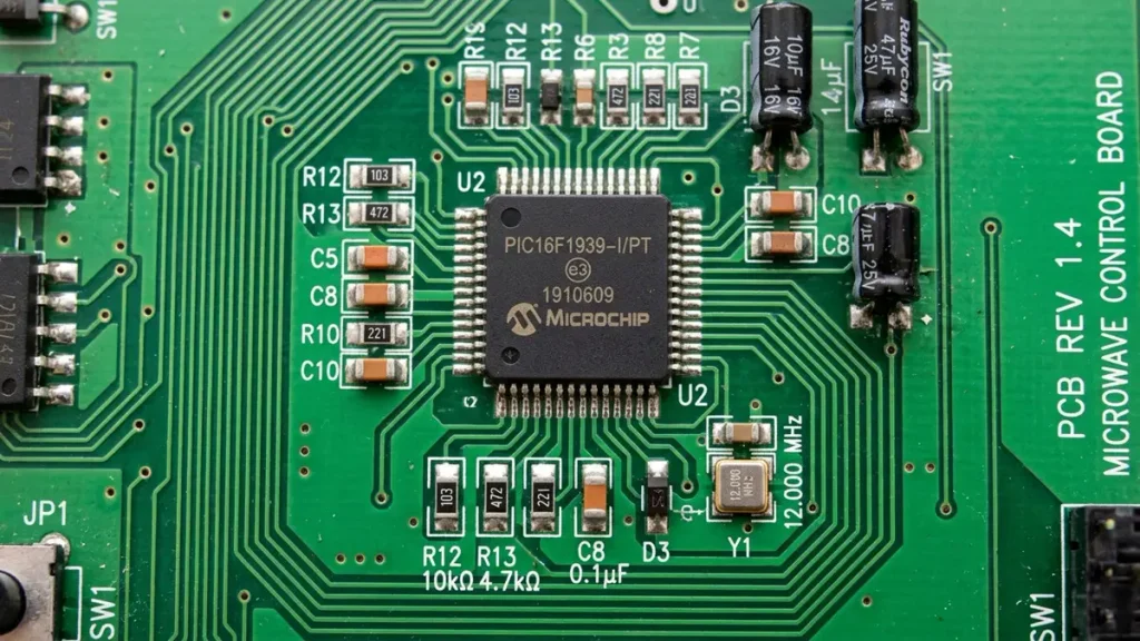
PCB Material: FR-4
Layer Count: 1–4 Layers
Board Thickness: 1.0–1.6 mm
Copper Thickness: 1 oz (35 μm)
Min. Trace / Space: 0.10 / 0.10 mm
Min. Hole Size: 0.30 mm
A reliable microwave oven PCB manufacturer must understand more than standard circuit board fabrication. The board must match the appliance’s electrical design, mechanical layout, component requirements and production specifications. Shenzhen Hongda Circuit Technology provides PCB fabrication and PCBA assembly for home appliance control boards, including microwave oven applications. Send your Gerber files and BOM to sales@pcbkr.com for a project review and quotation.
Microwave Oven PCB Manufacturing for Appliance OEMs
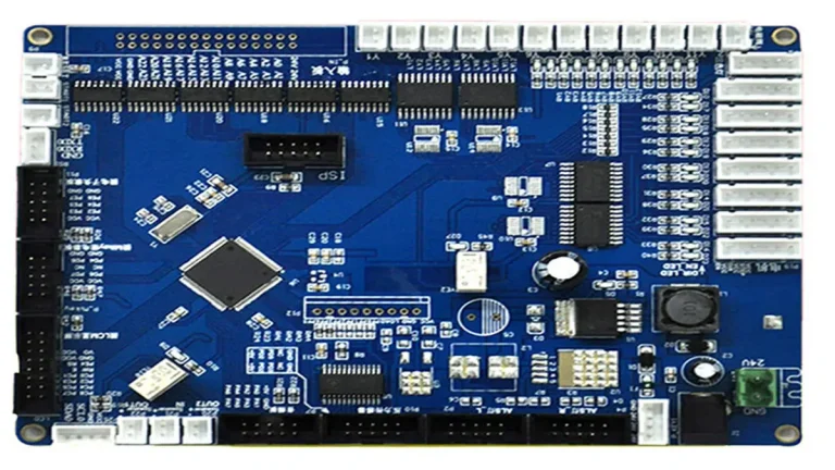
A microwave oven PCB is part of the appliance’s electronic control system. Depending on the product architecture, the control electronics may include a main controller, display interface, keypad or touch interface, power-control circuitry, relay interfaces and connectors for other appliance subsystems.
For an appliance manufacturer, the manufacturing challenge is not simply producing a board with the correct outline. The PCB must be fabricated and assembled to the approved design, fit the intended enclosure and connector arrangement, and meet the customer’s inspection and production requirements.
Hongda Circuit supports microwave oven PCB projects through two core manufacturing services:
- PCB fabrication: Manufacturing bare boards from customer-approved Gerber data and fabrication specifications.
- PCBA assembly: SMT and through-hole assembly according to the approved BOM, assembly drawings and process requirements.
The production scope can be configured for prototype orders, small batches or mass production. Component sourcing, firmware programming and functional testing can also be discussed as optional, project-dependent services.
This page focuses on microwave oven control PCB manufacturing and assembly. For a broader overview of control boards used across different household appliances, see our home appliance control board PCBA manufacturing page.
What Should a Microwave Oven PCB Manufacturer Understand?
Microwave oven control boards are often designed within strict mechanical and cost constraints. These requirements influence board construction, component placement, assembly methods and inspection planning.
Board Size and Mechanical Integration
The PCB outline is usually determined by the appliance enclosure and the positions of its mounting points, display, buttons, switches and wiring interfaces. A board that meets the electrical netlist but does not match the approved mechanical drawing can create assembly and installation problems.
Before production, buyers should confirm:
- Board outline and dimensional tolerances
- Mounting-hole positions and diameters
- Connector locations and orientations
- Component height restrictions
- Display, keypad and user-interface alignment
- Required board thickness and surface finish
Gerber data should be checked against the latest mechanical drawing. If the enclosure or mounting structure has changed, the manufacturing data should be reviewed before the production release.
Single-Layer, Double-Layer or Multilayer Construction
The appropriate layer count depends on the circuit design, routing density, electrical requirements and cost target. A single-layer PCB with components mounted on both sides may be suitable for some cost-sensitive appliance designs. However, it can make routing and component placement more restrictive than a double-layer design.
For procurement teams, the practical requirement is to select the construction that satisfies the approved electrical and mechanical design without adding unnecessary manufacturing cost. Hongda Circuit can manufacture according to the customer’s specified layer count, material, thickness and copper requirements.
Power-Control and Relay Interface Areas
Some microwave oven control designs include relay interfaces or other circuits connected to appliance power-control functions. These areas require careful attention to the approved copper layout, pad geometry, component footprint, soldering requirements and spacing defined by the design.
During manufacturing review, buyers and engineers should pay particular attention to:
- Copper width and copper thickness specified for relevant connections
- Pad dimensions and component footprint compatibility
- Solder-joint requirements for through-hole components
- Connector and terminal mechanical retention
- Clearance and creepage requirements specified by the product design
- Assembly drawing consistency and component polarity
PCB fabrication and PCBA assembly must follow the customer’s approved design and applicable product requirements. The PCB manufacturer should not independently change safety-related spacing, copper geometry or component ratings without engineering approval.
Critical Manufacturing Considerations for Microwave Oven PCBs
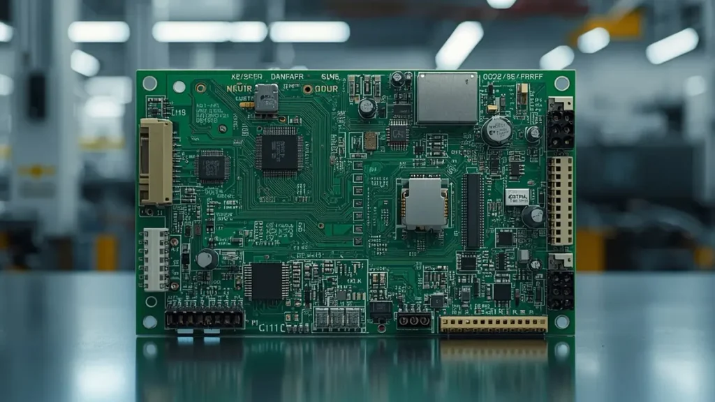
Critical Manufacturing Considerations for Microwave Oven PCB
Material, Copper Thickness and Board Thickness
FR-4 is commonly specified for many conventional appliance control boards, but the final material selection must follow the customer’s electrical, thermal, mechanical and regulatory requirements.
A procurement specification should identify the exact material grade or approved equivalent, board thickness, copper thickness and surface finish. These details should not be left to assumptions during quotation.
The following information helps avoid differences between the quoted product and the released production design:
| Specification | What the buyer should confirm |
|---|---|
| Base material | FR-4 grade or customer-approved material |
| Layer count | Single-layer, double-layer or multilayer |
| Board thickness | Nominal thickness and tolerance |
| Copper thickness | Finished copper requirement for each relevant layer |
| Minimum trace/space | Design minimums and manufacturing requirements |
| Minimum hole size | Finished hole diameter and tolerance |
| Surface finish | HASL, lead-free HASL, ENIG or another specified finish |
| Solder mask | Color, coverage and defined openings |
These are quotation inputs rather than fixed specifications for every microwave oven PCB. The final values should come from the released Gerber, stack-up and technical specification.
Component Availability and BOM Control
A complete BOM helps the manufacturer check component part numbers, package types, quantities and sourcing requirements before assembly. It also helps identify potential supply risks, obsolete components and proposed substitutions.
For microwave oven PCBA projects, the buyer should identify:
- Manufacturer part numbers and approved alternatives
- Component package and polarity information
- Customer-supplied versus manufacturer-sourced parts
- Any restricted or controlled component substitutions
- Special handling or storage requirements
- Programming files and test instructions, if applicable
A component substitution should never be treated as automatically acceptable because two parts share a similar package. Electrical ratings, pin assignments, operating characteristics and customer approval must be considered.
Hongda Circuit can discuss BOM and component sourcing support as an optional service based on project requirements. The approved BOM and substitution rules remain the basis for production.
Connector and Through-Hole Assembly Quality
Connectors, terminals, switches and other through-hole components can be important mechanical and electrical interfaces on an appliance control board. Their position, orientation, solder fill and mechanical stability should be checked against the assembly drawing and applicable acceptance criteria.
A loose or poorly connected interface can cause intermittent operation that may be difficult to reproduce during a brief inspection. For this reason, the inspection plan should identify critical connectors and solder joints rather than relying only on a general visual check.
The exact acceptance criteria should be agreed with the customer before production.
Microwave Oven PCBA Assembly Process
The PCBA process should follow the released manufacturing package and the assembly technology required by the board.
1. Engineering and Manufacturing Data Review
Before production, the manufacturer reviews the Gerber files, BOM, drill data, assembly drawings and relevant technical requirements. The review should identify missing information, footprint inconsistencies, unclear polarity markings and potential manufacturing conflicts.
For turnkey projects, component sourcing requirements and approved alternatives should also be confirmed.
2. Bare PCB Fabrication
The PCB is manufactured according to the approved material, layer structure, board thickness, copper thickness, drilling, solder mask and surface-finish specifications.
Dimensional requirements and electrical connectivity should be checked against the released manufacturing data. Any proposed deviation requires customer approval before it is introduced into production.
3. SMT and Through-Hole Assembly
Surface-mount components are assembled using the required solder-paste printing, component placement and reflow processes. Through-hole components are installed and soldered according to the assembly drawing and process requirements.
The assembly plan should account for component orientation, connector positions, soldering access and any special process instructions.
4. Inspection and Electrical Verification
Inspection methods should be selected according to board design, component package, production volume and customer requirements. Depending on the project, available inspection methods may include:
- Automated optical inspection (AOI)
- X-ray inspection for applicable hidden solder joints
- Flying-probe electrical testing
- Visual inspection of critical solder joints and connectors
- Customer-defined functional testing, when the test procedure and equipment are agreed
Hongda Circuit has 3D AOI, X-ray and four-wire Kelvin flying-probe inspection capabilities. The applicable inspection plan is determined by the product design and quotation scope; these methods should not be interpreted as tests automatically included in every order.
For more details about the assembly service scope, visit our PCB assembly service page.
EMC, ESD and Electrical Reliability: What Buyers Should Verify
Electromagnetic compatibility should be considered during product design, not treated as a problem that can always be solved after PCB fabrication. Component selection, circuit protection, power distribution, grounding, signal routing and functional grouping can all affect the final system’s immunity.
For a microwave oven PCB project, the engineering team should define the relevant test requirements before production. These may include applicable ESD, EFT, surge, electrical and system-level verification requirements, depending on the product and target market.
A PCB or PCBA supplier can manufacture to approved design data and perform agreed board-level inspections or tests. However, passing a board-level inspection does not establish that the complete microwave oven complies with all appliance safety, EMC or regulatory requirements.
Buyers should distinguish between:
- PCB manufacturing verification: Board dimensions, drilling, copper, surface finish and electrical connectivity.
- PCBA assembly verification: Component placement, solder quality, polarity, assembly workmanship and agreed electrical tests.
- Product-level compliance: Testing of the complete appliance, including its enclosure, wiring, power system, firmware and safety-related functions.
The product manufacturer remains responsible for defining and validating the complete appliance’s applicable compliance requirements.
Quality Inspection and Testing for Microwave Oven PCBA
A useful quality plan connects each inspection method to a specific manufacturing risk. It should be agreed before mass production so that the buyer and manufacturer share the same acceptance criteria.
| Inspection or test | Manufacturing purpose |
|---|---|
| Incoming material and component checks | Verify parts against the approved BOM and purchasing requirements |
| AOI | Identify visible component placement, polarity and soldering defects within inspection coverage |
| X-ray | Inspect applicable hidden solder joints and connections |
| Flying-probe test | Verify electrical connectivity against the approved test data |
| Visual inspection | Check workmanship, connectors, solder joints and visible damage |
| Functional test | Verify defined board functions using an agreed test procedure and setup |
Not every board requires every inspection method. For example, X-ray is most relevant when the assembly contains solder joints that cannot be adequately evaluated by optical inspection. Functional testing requires a defined test method, suitable fixture or interface, test limits and an agreed responsibility for test development.
Hongda Circuit can review the customer’s inspection requirements and determine which available manufacturing checks are appropriate for the project.
Common Microwave Oven PCB Manufacturing Risks
The following issues are useful checkpoints for OEM buyers during supplier qualification and production planning.
Connector and Solder-Joint Problems
Connectors and through-hole components may experience mechanical stress during wiring, installation or service. Buyers should specify critical connector requirements and confirm that the assembly drawing identifies the correct position, orientation and soldering method.
Display or Control Interface Misalignment
A PCB may be electrically correct but still fail to fit the product if the display, keypad, switch or mounting-hole positions do not match the mechanical design. Cross-checking the PCB data against the latest mechanical drawing helps reduce this risk.
Power-Circuit Assembly Defects
Soldering defects, incorrect component orientation or deviations from the approved component specification can affect power-control circuits. Inspection should focus on the components and connections identified as critical by the customer’s design and quality team.
Component Obsolescence and Substitution
Long product lifecycles can create component availability problems. An obsolete component may require an approved alternative or a revised BOM. Buyers should establish a formal substitution approval process before production rather than allowing unapproved changes during assembly.
EMC Problems Discovered Too Late
If EMC requirements are not considered until product validation, changes may affect the PCB layout, component selection or even the mechanical design. The OEM engineering team should provide applicable EMC requirements and test responsibilities early in the project.
Prototype, Small-Batch and Mass Production Support
Microwave oven PCB projects may require different production quantities during product development and commercial release.
Prototype production helps verify the released design, component selection, mechanical fit and assembly process before a larger order is placed.
Small-batch production supports pilot builds, engineering validation, market trials and initial product launches. It also allows the buyer to review manufacturing consistency and inspection records before scaling.
Mass production requires stable production data, approved components, documented process requirements and an agreed quality-control plan. Revision control is especially important: the Gerber, BOM and assembly drawing used for production must correspond to the same approved product revision.
Hongda Circuit supports prototype, small-batch and mass-production requirements for PCB fabrication and PCBA assembly. The production plan, lead time, material sourcing and inspection scope are confirmed against the actual project files and order quantity.
What Should You Send for a Microwave Oven PCB Manufacturing Quote?
Providing complete technical information helps the manufacturer assess feasibility and prepare a more accurate quotation.
For bare PCB fabrication, prepare:
- Gerber files, including copper, solder mask, silkscreen and outline layers
- Drill files
- Layer count and stack-up, if applicable
- Base material and material grade
- Board thickness and copper thickness
- Surface finish
- Required electrical and dimensional specifications
- Order quantity and target delivery schedule
For PCBA assembly, also provide:
- Complete BOM with manufacturer part numbers
- Pick-and-place file, if available
- Assembly drawings
- Component polarity and special assembly notes
- Customer-supplied component list, if applicable
- Approved component alternatives or substitution restrictions
- Programming files and test procedures, if required
- Functional test requirements and acceptance criteria
If you are developing a new board or reproducing an existing design, provide the available PCB files, sample photographs and technical information. The manufacturer must review the available data before confirming whether the project can be reproduced.
For component sourcing requirements, see our component sourcing service.
Why Work with Hongda Circuit for Microwave Oven PCB Manufacturing?
Shenzhen Hongda Circuit Technology Co., Ltd. provides PCB fabrication and PCBA assembly for electronic control boards used in home appliance applications, including microwave oven projects.
Our manufacturing support is based on the customer’s approved design and production requirements:
- PCB fabrication and PCBA assembly: Support for bare-board manufacturing and assembled control boards.
- SMT and through-hole assembly: Assembly according to the released BOM and assembly documentation.
- Inspection resources: 3D AOI, X-ray and four-wire Kelvin flying-probe capabilities, applied according to the project inspection plan.
- Flexible production quantities: Prototype, small-batch and mass-production requirements can be reviewed.
- Project-based sourcing and testing: Component sourcing, firmware programming and functional testing can be discussed as optional services where the project scope supports them.
- Engineering data review: Gerber, BOM, stack-up, assembly drawings and customer quality requirements can be reviewed before quotation.
We do not assume that every microwave oven PCB uses the same material, layer count, copper thickness or test procedure. The manufacturing specification and quotation are based on the actual product design.
To discuss your microwave oven PCB project, contact our team:
Shenzhen Hongda Circuit Technology Co., Ltd.
Email: sales@pcbkr.com
Website: https://www.pcbkr.com/
Send your Gerber files, BOM, target quantity and required inspection scope to request a manufacturing review and quotation.
Frequently Asked Questions
How do I choose a reliable microwave oven PCB manufacturer?
Check whether the supplier can manufacture to your released Gerber data, follow the approved BOM, support the required SMT and through-hole assembly processes, and provide inspection methods appropriate to the board. Also confirm revision control, component sourcing rules, production quantity and the acceptance criteria before placing an order.
Can Hongda Circuit manufacture both microwave oven PCBs and assembled PCBAs?
Yes. Hongda Circuit supports PCB fabrication and PCBA assembly for home appliance control board applications, including microwave oven projects. The quotation can cover bare PCB manufacturing, assembly or a combined scope, depending on the customer’s files and requirements.
What files are required for a microwave oven PCB assembly quotation?
The main documents are Gerber files, drill files, BOM and assembly drawings. Pick-and-place data, stack-up information, programming files, test procedures and special process requirements should also be supplied when applicable. The more complete the manufacturing package, the more accurately the supplier can assess the project.
Can you source components and perform functional testing for microwave oven PCBA?
Component sourcing and functional testing can be discussed as optional, project-dependent services. The customer should provide the BOM, approved alternatives, programming requirements and functional test specifications. Test fixtures, test limits and responsibilities must be agreed before the quotation is finalized.
Can you support microwave oven PCB prototypes and mass production?
Hongda Circuit can review prototype, small-batch and mass-production requirements for PCB fabrication and PCBA assembly. The feasible production plan, lead time and inspection scope depend on the board design, component availability, order quantity and customer requirements. Contact sales@pcbkr.com with your project files for assessment.
Request a Microwave Oven PCB Manufacturing Quote
For OEM and ODM microwave oven control board projects, send your Gerber files, BOM, order quantity and technical requirements to sales@pcbkr.com.
Hongda Circuit will review the manufacturing scope and discuss the appropriate PCB fabrication, PCBA assembly and inspection requirements.
Microwave Oven PCB – Data Sheet
| Item | Specification |
|---|---|
| Product Type | Microwave Oven Control PCB |
| PCB Material | FR-4 |
| Layer Count | 1–4 Layers |
| Board Thickness | 1.0–1.6 mm |
| Copper Thickness | 1 oz (35 μm) |
| Min. Trace / Space | 0.10 / 0.10 mm |
| Min. Hole Size | 0.30 mm |
| PCB Fabrication | Custom PCB Manufacturing |
| Assembly Type | SMT / THT |
| PCB Assembly | PCBA Manufacturing |
| Component Sourcing | Available upon request |
| Inspection | 3D AOI / X-ray / Flying Probe |
| Functional Testing | Optional, project-dependent |
| Production Volume | Prototype / Small Batch / Mass Production |
| Application | Microwave Oven Control Systems |
| Customization | Based on Gerber, BOM and Customer Requirements |
Technical specifications are indicative reference values. Final material, dimensions, layer count, copper thickness, trace/space, hole size and inspection requirements are subject to design review and project confirmation.
About Author
David Chen LinkedIn Profile
David Chen is a Senior RF/PCB Process Engineer at Shenzhen Hongda Circuit Technology Co., Ltd., with over 12 years of experience in high-frequency PCB fabrication, impedance-controlled stack-up design, and Rogers/PTFE laminate processing. He also boasts an extensive professional background in PCBA manufacturing, PCBA testing, and PCBA optimization, with specialized expertise in high-precision PCBA fault analysis and rigorous PCBA reliability testing. The author has worked with high-layer-count server PCB fabrication, ultra-low-loss backplane stackups, and thermo-mechanical reliability optimization for AI infrastructure projects involving 112G and 224G PAM4 architectures. Skilled in complex circuit design and cutting-edge advanced PCB manufacturing processes, he delivers solutions that elevate product durability and performance across industrial applications. His technical articles focusing on PCBA manufacturing workflows and testing methodologies are widely cited by industry peers and technical platforms, and have gained attention and recognition from industry colleagues.