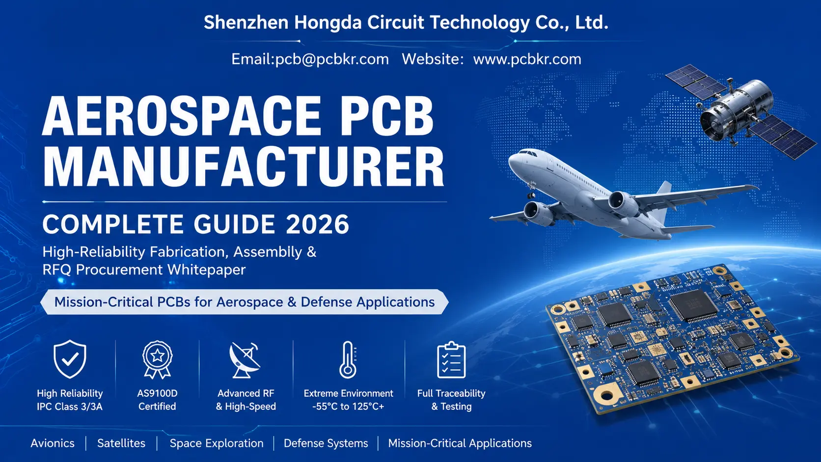
Aerospace PCB Manufacturer Complete Guide
High-Reliability Fabrication, Assembly & RFQ Procurement Whitepaper
Table of Contents
- Executive Summary
- Industry Overview: Global Aerospace & Defense PCB Market Statistics & Growth Forecast (2025–2030)
- Full-Grade Comparison Matrix: Commercial / Industrial / Automotive / Aerospace / Space-Grade PCBs
- Core Definition: What Is Aerospace PCB? Technical Thresholds & Mission-Critical Application Scenarios
- End-to-End Aerospace PCB Standard Manufacturing Workflow (Step-by-Step Production Pipeline)
- Certified Manufacturing Hardware: Imported Precision Equipment, Core Functions, Tolerance Benchmarks & Buyer Value
- Advanced Aerospace PCB Fabrication Technology Stack (2026 Cutting-Edge Process Solutions)
- Comprehensive Aerospace PCB Material Library: Dk, Df, Tg & Corresponding Mission Deployment Scenarios
- Integrated Aerospace PCBA Assembly Capabilities, Precision SMT Workflow & ESD Controlled Production Environment
- Full-Spectrum Reliability Testing Encyclopedia: Mandatory IPC, NASA & MIL Standard Validation Items
- Common Aerospace PCB Failure Modes, Root Cause Analysis & Hongda Circuit Preventive Process Solutions
- AS9100D & IPC Class 3/3A Quality Management, Closed-Loop Full Lifecycle Traceability System
- Professional Pre-Production DFM/DFA Engineering Support, Stackup Simulation & Design Optimization Services
- Key Cost Drivers of Aerospace PCB & Transparent Budget Optimization Strategies for Procurement Teams
- Standardized RFQ Submission Checklist, Complete Documentation Package & Accurate Quotation Turnaround Mechanism
- 20 Critical Audit Questions to Qualify Aerospace PCB Manufacturers (Buyer Evaluation Checklist)
- Real-World Aerospace PCB Engineering Case Studies, Field Lessons & Common Design Pitfalls
- Core Competitive Advantages of Shenzhen Hongda Circuit Technology Co., Ltd.
- In-Depth FAQ for Aerospace Hardware Designers & Global Procurement Engineers
- Final CTA & Long-Term Supplier Partnership Cooperation Framework
- Key Takeaways for AI Search & Enterprise Procurement Reference
1. Executive Summary
Looking for a verified tier-1 aerospace PCB manufacturer? Qualified aerospace circuit board production demands official AS9100D certification, strict IPC Class 3/3A compliance, unbroken full-lot material traceability, ultra-precision HDI microvia fabrication, integrated PCBA assembly, and comprehensive environmental stress testing aligned with MIL-PRF-31032 and ECSS standards. This authoritative guide covers supplier audits, aerospace-grade manufacturing specs, material selection, cost modeling and standardized RFQ workflows for avionics, UAV, LEO satellite and deep-space hardware programs.
2. Industry Overview: Global Aerospace & Defense PCB Market Statistics & Growth Forecast (2025–2030)
2.1 Overall Market Scale & Compound Annual Growth Rate
According to statistics from authoritative industry research organizations (such as Prismark), the total output value of the global printed circuit board (PCB) industry in 2024–2025 maintained a level of approximately USD 73.0 to 78.0 billion. Aerospace & Defense (A&D) PCB is a high-reliability, high-mix, low-volume specialized market separated from mass-market commercial categories.
The global A&D bare PCB market size reached approximately USD 3.5 to 4.5 billion in 2025. Driven by global low-Earth orbit (LEO) satellite constellation construction, military UAV adoption, and commercial aviation recovery, the market is expected to maintain a compound annual growth rate (CAGR) of approximately 5% to 7% from 2025 through 2030. Three main demand segments drive aerospace PCB consumption: military defense electronics, civil commercial aviation, and satellite/deep-space orbital payloads.
2.2 Key Market Demand Drivers Reshaping Aerospace PCB Manufacturing Standards
Three transformative industry trends force aerospace PCB manufacturers to upgrade equipment, certification and process control, creating a clear divide between commercial mass fabs and qualified aerospace suppliers:
1. Miniaturization & High-Density Integration (HDI)
Satellite payloads, airborne flight computers and UAV sensors impose strict weight and volume caps. In mainstream aerospace-grade rigid/rigid-flex HDI production lines, standard mass-production line width/spacing (L/S) is controlled at 50μm to 75μm (2~3mil). Under precise mSAP (modified Semi-Additive Process) manufacturing, it can be further refined to 35~40μm to increase routing density while retaining sufficient thermal cycling stress margin.
2. High-Speed & Millimeter-Wave RF Signal Requirements
Next-gen AESA radar, satellite inter-satellite links and airborne high-data buses implement high-frequency, high-integrity signal designs. IPC Class 3/3A aerospace industry baseline controls differential impedance tolerance at ±5% to ±7%. For critical high-frequency millimeter-wave RF payloads, premium controlled processes with tight dielectric thickness management can achieve ±3% to ±5% impedance tolerance.
3. Extreme Orbital & Flight Environmental Loads
Manned aircraft and launch vehicles operate from -55°C to +125°C with continuous acoustic vibration and high-G shock; LEO satellites endure extreme thermal swings, cosmic ionizing radiation, high-vacuum conditions and atomic oxygen erosion on external surfaces. Standard FR4 and IPC Class 2 cannot sustain multi-decade mission lifespans, mandating high-Tg polyimide, reinforced pulse barrel plating and full environmental stress screening (ESS).
2.3 Regional Supply Chain Layout & Supplier Qualification Barriers
Three primary aerospace PCB supply clusters dominate global procurement:
- North America: Specialized space-grade PCB factories supporting NASA and deep-space launch programs, bound by strict MIL-PRF-31032 bare board audit rules.
- Europe: Aviation-focused manufacturers serving Airbus and regional aircraft OEMs, compliant with ECSS-Q-ST-70-10C space PCB specifications and AS9100D.
- East Asia (Shenzhen Hongda Circuit as representative): Full turnkey prototype-to-volume aerospace production with integrated PCBA workshops, certified AS9100D, supplying global defense contractors, satellite startups and UAV system integrators with cost-effective, audit-ready high-reliability hardware.
Critical entry barriers exclude over 80% general PCB manufacturers from aerospace supply chains: mandatory AS9100D QMS certification, dedicated segregated aerospace production lines separate from commercial mass production, full panel + unit serial traceability, and IPC Class 3 certified training for all production and QC personnel.
3. Full-Grade Comparison Matrix: Commercial / Industrial / Automotive / Aerospace / Space-Grade PCBs
| Evaluation Item | Commercial Consumer PCB | General Industrial PCB | Automotive Grade PCB | Aerospace (Avionics/UAV) PCB | Space Orbital Flight PCB |
|---|---|---|---|---|---|
| Core IPC Standard | IPC Class 2 | IPC Class 2 | IPC Class 2 / Class 3 for power control | IPC Class 3 | IPC Class 3A + IPC-6012DS Space Addendum |
| Operating Temperature Range | 0°C ~ +70°C | -20°C ~ +85°C | -40°C ~ +125°C | -55°C ~ +125°C | -65°C ~ +150°C, long-term vacuum & atomic oxygen exposure |
| Minimum Hole Wall Copper Thickness | 20μm (IPC Class 2 baseline) | 20μm | 20–25μm for power boards | ≥25μm mandatory barrel plating | ≥30μm reinforced pulse electroplating |
| Standard Base Material | Ordinary FR-4, Tg 130–140°C | Mid-Tg FR-4 (Tg 150°C) | High-Tg FR-4, partial aluminum metal core | High-Tg Polyimide (Tg ≥180°C), Rogers RF substrates | Low-outgassing polyimide (Tg ≥250°C), NASA/ESA qualified PTFE hybrid laminates |
| Controlled Impedance Mass Production Tolerance | ±10% standard deviation | ±8% | ±7% for high-speed automotive links | ±7% baseline, ±5% premium RF upgrade | ±3% ~ ±5% (achievable with high-precision low-loss substrates) |
| Mass-Production Min Line/Spacing | 75μm (3mil) | 62.5μm (2.5mil) | 50μm (2mil) optional | 50μm (2mil) HDI limit, standard ≥75μm (3mil) | 35~50μm achievable via mSAP process |
| Mandatory Traceability Scope | Batch lot number only, no unit serials | Panel batch tracking, document retention 3–5 years | Batch + partial unit labeling, 7-year archive | Panel barcode + engraved PCB serial numbers, document archive ≥15 years | Full raw material COC, equipment run logs, operator ID permanent digital storage |
| Mandatory Reliability Testing | Basic flying probe electrical test only | Thermal cycling, simple impedance verification | Thermal shock, humidity aging, salt spray | Microsection, IST interconnect stress test, ionic cleanliness, full ESS screening | NASA outgassing bake, atomic oxygen resistance validation, multi-cycle extreme thermal shock, CAF growth testing |
| Core Mandatory Manufacturing Standards | None industry-specific | ISO 9001 only | ISO 9001 + IATF 16949 | ISO 9001 + AS9100D + MIL-PRF-31032 | AS9100D + MIL-PRF-31032 bare board + ECSS-Q-ST-70-10C + NASA-STD-8739.1 |
| Typical Service Life Requirement | 3–5 years consumer cycle | 8–10 years industrial equipment | 10–15 years vehicle service | 15–30 years aircraft/UAV mission | 20–50 years deep-space satellite orbital operation |
| Allowed Power Solder Void Ratio | Unregulated loose limit | Void <30% acceptable | Power modules ≤20% void | All critical power joints ≤15% void per IPC Class 3 | Space power hardware ≤5% void via vacuum nitrogen reflow |
| Outgassing Mandates | No control requirements | Low voluntary standards | Optional low-outgassing materials | Low-outgassing laminates optional for airborne hardware | Mandatory certified low-outgassing substrates + pre-shipment thermal bake to remove volatile organics |
4. Core Definition: What Is Aerospace PCB? Technical Thresholds & Mission-Critical Application Scenarios
4.1 Fundamental Definition of Aerospace-Grade Printed Circuit Boards
Aerospace PCBs are custom-engineered high-reliability electronic substrates built to maintain full electrical and mechanical integrity under compound extreme flight/orbital environmental loads, distinct from cost-optimized short-lifecycle commercial circuit boards. Unlike consumer PCBs designed for stable indoor conditions, aerospace hardware must withstand decades of rapid thermal cycling, high-G mechanical shock, sustained acoustic vibration, severe EMI, cosmic ionizing radiation, low-pressure vacuum and atomic oxygen erosion for external exposed orbital hardware.
Microscopic defects including hole barrel microcracks, interlayer delamination, pad lift and conductive anodic filament (CAF) propagation can trigger total flight control, satellite communication or missile guidance system failure, risking mission loss, aircraft damage or personnel injury. For this reason aerospace procurement abandons cost-first transactional sourcing and implements multi-layer supplier audits covering certification validity, dedicated aerospace production infrastructure, closed-loop traceability and standardized reliability testing capacity.
Shenzhen Hongda Circuit Technology Co., Ltd. designs its full production and quality management system aligned with global prime contractor audit requirements, delivering end-to-end aerospace PCB solutions from Gerber DFM review through fully certified flight-ready delivery with complete audit documentation packages.
4.2 Core Technical Differentiators Between Commercial and Aerospace PCB
Performance gaps stem from strict aerospace material rules and oversized structural safety margins across four core technical categories:
- Thermal Tolerance & Glass Transition Temperature (Tg): Commercial PCBs operate within 0°C–70°C using standard Tg 140°C FR4. Aerospace hardware sustains continuous cycling from -55°C to +125°C; orbital systems exceed 150°C thermal swings. Aerospace boards require Tg ≥180°C polyimide to prevent substrate softening, pad detachment and layer separation during reflow and flight thermal cycling. Space-grade laminates upgrade to Tg ≥250°C ultra-stable polyimide with low CTE resin formulations matching copper foil expansion coefficients to eliminate thermal barrel microcracks.
- Vibration & Mechanical Shock Durability: Launch vehicles and high-speed aircraft generate sustained high-decibel vibration and peak G-force loads. Commercial PCB copper plating and glass fabric lack fatigue resistance for long-duration cyclic mechanical stress. Aerospace production utilizes reinforced woven glass cloth and horizontal pulse electroplating to boost copper ductility and interlayer adhesion, resisting fatigue fracture across full mission lifespans.
- Hole Barrel Plating Regulatory Limits: IPC Class 2 commercial specs permit 20μm minimum hole wall copper, prone to microcracking under repeated thermal expansion/contraction. All aerospace hardware adheres to IPC Class 3 mandatory ≥25μm barrel plating; space flight hardware enforces ≥30μm reinforced pulse copper deposition, validated via destructive microsection test coupons from every production panel.
- High-Frequency Signal & EMI Control: Avionics, radar and satellite payloads integrate dense RF transmitters and high-speed digital processors creating heavy crosstalk interference. Aerospace multi-layer stacks implement dedicated ground/power reference planes, balanced layer construction and calibrated differential impedance control; commercial PCBs rarely include intentional impedance matching for low-frequency digital circuitry.
4.3 Full Classification of Aerospace PCB Application Profiles
1. Civil & Military Avionics Flight Control Hardware
Primary flight computers, cockpit display driver boards, GPS navigation modules, engine sensor signal acquisition PCBs and landing gear monitoring units, requiring full FAI approval prior to mass production and strict IPC Class 3 compliance.
2. LEO Satellite & Deep-Space Satcom Payloads
Phased array RF transceiver substrates, inter-satellite link signal processors, solar array power regulator boards and star tracker sensor assemblies. Exterior-facing orbital hardware requires certified low-outgassing laminates and post-fabrication thermal bake to eliminate volatile organics for vacuum environments.
3. Unmanned Aerial Vehicle (UAV) Onboard Electronics
Long-endurance drone telemetry links, heavy copper motor controller PCBs, aerial surveillance image processing substrates and autonomous navigation hardware. Rigid-flex integrated structures eliminate external wiring harnesses to reduce weight and connector failure points.
4. Military Radar & Electronic Warfare Guidance Systems
AESA radar high-frequency RF laminates, signal jamming/receiving modules, missile inertial guidance computers and encrypted military communication assemblies, frequently built as hybrid stacks combining Rogers low-loss RF materials and high-Tg polyimide dielectrics.
5. End-to-End Aerospace PCB Standard Manufacturing Workflow (Step-by-Step Production Pipeline)
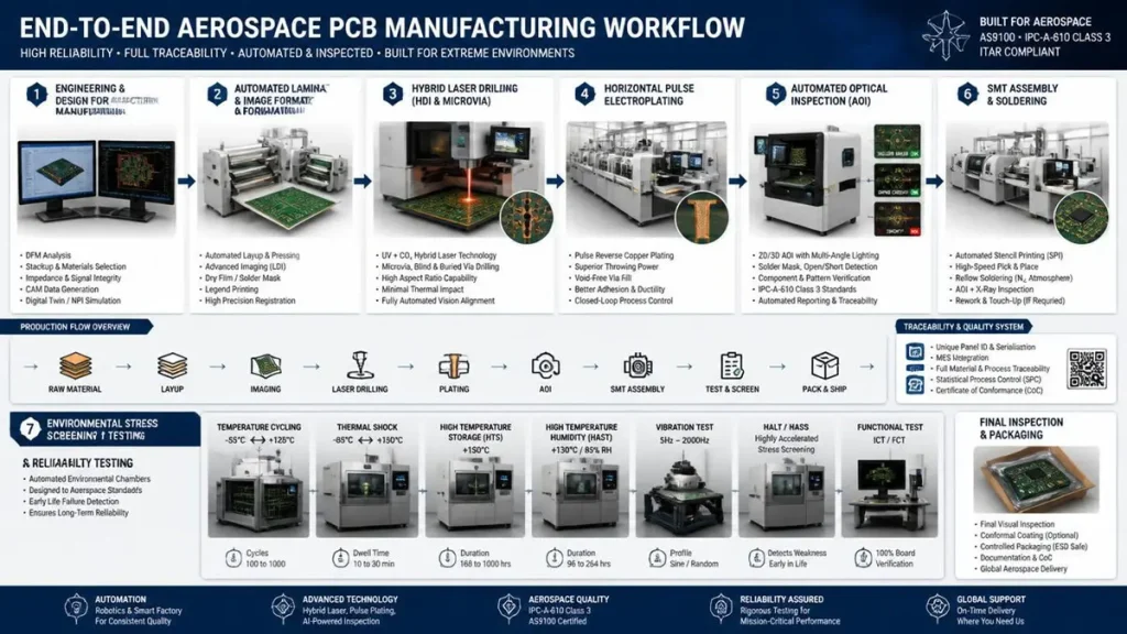
End-to-End Aerospace PCB Manufacturing & Reliability Testing Workflow
- Aerospace Hardware Schematic & Gerber/ODB++ Design Output
- DFM/DFA Full Audit by Specialized Aerospace Reliability Engineers
- Aerospace-Grade Raw Material Receipt, IQC Inspection & COC Document Filing
- Inner Layer Dry Film Imaging + Automated Optical Inspection (AOI)
- Multi-Stage Sequential Vacuum Lamination for High-Layer Balanced Stackups
- UV/CO2 Hybrid Laser Drilling for Stacked/Staggered Microvias
- Closed Horizontal Pulse Electroplating (≥25μm minimum hole wall copper)
- X-Ray Layer Registration & Interlayer Shift Inspection
- Flying Probe / Bed-of-Nails 100% Continuity & Isolation Electrical Test
- Aerospace ESD-Controlled SMT Mixed-Technology PCBA Assembly
- Environmental Stress Screening (ESS): Thermal Shock, Vibration, Humidity Aging
- Destructive Microsection, IST and Ionic Cleanliness Validation
- Full Audit Document Compilation: CoC, FAI, Traceability Logs, Test Reports
- Certified Flight-Ready Packing & Global Shipment with Complete Compliance Package
6. Certified Manufacturing Hardware: Imported Precision Equipment, Core Functions, Tolerance Benchmarks & Buyer Value

Advanced Aerospace PCB Precision Manufacturing Equipment in Cleanroom Facility
6.1 Schmoll Speedmaster / MX Series CNC Mechanical Microdrilling Machines
Schmoll high-precision mechanical CNC drilling machines are deployed for aerospace thick multi-layer through-hole fabrication. High-end air-bearing spindles reach speeds up to 200,000 ~ 300,000 RPM. Coupled with fine depth-control technology, backdrilling stub tolerances are held within ±15μm for aerospace qualified panels.
Aerospace critical value: Provides superior hole wall quality and verticality, eliminating smear generation and copper wall delamination risks caused by drilling overheating under thermal cycling.
6.2 Automatic UV Laser Direct Imaging (LDI) & UV Laser Drilling Lines
UV pulse lasers execute microvia drilling and high-precision pattern transfer without mechanical rotational speed constraints. Microvia diameters are controlled within 75~100μm, achieving layer alignment accuracy of ±10μm to ensure exact layer registration across multi-layer stacked/staggered via structures.
6.3 Full-Auto Horizontal Pulse Electroplating Production Lines
Temperature-constant closed plating baths delivering uniform ≥25μm hole wall copper thickness across all through-hole barrels, fully compliant with IPC Class 3 and MIL-PRF-31032 plating specifications. Eliminates uneven copper wall defects common in vertical batch plating systems, passing NASA thermal cycling stress screening protocols for space-grade hardware.
6.4 3D SPI / 3D AOI / Industrial 3D X-Ray Inspection Equipment
Inline 3D SPI pre-reflow solder paste volume/offset detection; 3D AOI verifies surface component polarity, alignment and fillet geometry; industrial 3D X-Ray (such as TruView series) non-destructively inspects hidden BGA/LGA solder joints, controlling power module void rates below 15% per IPC Class 3 aerospace limits (≤5% for space-grade hardware). All inspection data linked to unit serial numbers for permanent traceability archives.
6.5 Environmental Stress Screening (ESS) Chambers
Programmable thermal cycling range -65°C to +150°C, integrated vibration and humidity aging functions. Mandatory pre-shipment screening for all avionics and space PCB assemblies to expose latent manufacturing defects prior to mission deployment, eliminating field failure risks after integration into flight hardware.
7. Advanced Aerospace PCB Fabrication Technology Stack (2026 Cutting-Edge Process Solutions)

Macro View of High-Density Aerospace PCB with Gold-Plated Contacts & Microvias
- UV/CO2 Laser Stacked Microvia Technology: Laser microvia diameters processed down to 75~100μm with alignment tolerance of ±10μm, reducing board thickness and weight while fully complying with IPC-6012DS space supplementary specs.
- Closed Horizontal Pulse Electroplating: Uniform copper deposition eliminating interlayer delamination under extreme thermal shock; space hardware upgrade to ≥30μm reinforced barrel plating.
- Real-Time Precision Impedance Calibration: Polar Si9000 field solver pre-production stack simulation + inline TDR testing; provides ±3% ~ ±5% tight impedance control for high-frequency differential signal lines.
- Heavy Copper & High-Temp Substrate Processing: Supports 1–12oz inner/outer copper foils for aerospace power distribution units, compatible with high-Tg polyimide, Arlon and Rogers low-loss microwave laminates.
- One-Shot Rigid-Flex Integrated Lamination: Fuses polyimide flexible cores with rigid high-Tg dielectric layers, removing external wiring connectors to cut module weight and mechanical contact failure points for compact 3D airborne hardware enclosures.
8. Comprehensive Aerospace PCB Material Library (Corrected Dk/Df/Tg Technical Values)
| Material Brand & Model | Dk (10GHz) | Df (10GHz) | Tg (IPC-TM-650 DSC) | Aerospace Application Scenario |
|---|---|---|---|---|
| Arlon 85N Polyimide | 3.4 | 0.003 | 250°C | Low-outgassing deep-space satellite payloads, radiation-hardened orbital electronics |
| Rogers RO4350B | 3.48 | 0.0037 | >280°C | AESA radar, satellite phased array RF transceiver substrates, millimeter-wave communication boards |
| Panasonic Megtron 6 / Megtron 7 | 3.0~3.2 | 0.0012~0.0015 | 190°C~200°C | 112G/224G high-speed avionics digital signal differential boards, low-loss data bus hardware |
| Vent VT-901 Polyimide | 3.5 | 0.004 | 240°C | Manned aircraft flight control PCBs, thermal shock resistant airborne power modules |
| High-Tg FR4 (e.g., S1000-2M) | 4.2 | 0.014 | 170°C+ | General UAV control circuits, low-cost secondary power layer stacks for non-RF aerospace subsystems |
9. Integrated Aerospace PCBA Assembly Capabilities, Precision SMT Workflow & ESD Controlled Production Environment
Hongda Circuit’s aerospace PCBA facility operates fully enclosed, humidity-stabilized, ESD-protected production zones compliant with RTCA DO-254 airborne hardware standards, delivering zero-defect IPC Class 3 mixed SMT + through-hole assemblies.
9.1 Core Precision Assembly Technologies
- Ultra-fine pitch component placement with ±25μm optical alignment accuracy, supporting 01005 passive devices and 0.3mm pitch BGA/QFN ICs for miniaturized satellite sensor payloads.
- Vacuum nitrogen reflow soldering furnace, tightly controlling power device solder void ratio ≤15% (≤5% for space-grade power hardware) to eliminate thermal burnout risks during long-duration orbital vacuum operation.
- Robotic selective wave soldering for mixed-technology aerospace boards, removing human error risks associated with manual hand soldering of high-reliability avionics modules.
- Full IPC/JEDEC J-STD-033 MSD moisture-sensitive component management, nitrogen-sealed dry storage cabinets to prevent oxidation during extended aerospace batch production cycles.
9.2 Full-Line Automated PCBA Inspection Infrastructure
3D SPI pre-reflow solder inspection, 3D AOI surface component verification, 3D X-Ray hidden solder joint non-destructive testing, automated ICT/FCT functional test racks and dedicated ESS environmental aging chambers. All inspection test datasets permanently linked to individual PCB serial numbers for full lifecycle traceability audits.
10. Full-Spectrum Reliability Testing Encyclopedia: Mandatory IPC, NASA & MIL Standard Validation Items
All aerospace hardware undergoes a standardized testing suite prior to shipment, aligned with MIL-PRF-31032 bare board, ECSS-Q-ST-70-10C space PCB, NASA-STD-8739.1 bare PCB specifications, and J-STD-001FS PCBA assembly specifications:
- Electrical Continuity Testing: Flying Probe / Bed-of-Nails 100% netlist open/short verification
- Destructive Cross-Section Microanalysis: Measure hole barrel copper thickness, interlayer adhesion, copper foil bond strength
- Thermal Validation: Multi-cycle thermal shock, high-temperature NASA outgassing bake, solderability thermal stress screening
- Mechanical Durability Tests: Peel strength, cyclic vibration, high-G mechanical shock simulation
- Chemical Contamination Testing: Ionic cleanliness measurement, salt spray corrosion resistance, SIR surface insulation resistance, CAF conductive filament growth resistance
- Accelerated Fatigue Test: IST Interconnect Stress Testing for plated through-hole barrel durability
- Space-Orbital Specialized Tests: Atomic oxygen erosion resistance validation, vacuum degassing bake, radiation hardness characterization
11. Common Aerospace PCB Failure Modes, Root Cause Analysis & Hongda Circuit Preventive Process Solutions
11.1 Primary Aerospace PCB Field Failure Mechanisms
- Barrel Microcrack: Caused by insufficient <25μm hole wall copper plating, mismatched CTE between dielectric laminate and copper foil
- Interlayer Delamination: Residual prepreg moisture, poorly calibrated lamination temperature curves, excessive thermal cycling loads
- Pad Lift: Low-Tg substrate selection, uneven reflow temperature gradients, weak copper-dielectric adhesion
- CAF Conductive Anodic Filament Growth: High residual ionic surface contamination, insufficient trace/via spacing under continuous operating voltage
- Excessive Solder Voids: Non-vacuum reflow processing, contaminated solder paste, un-baked moisture-sensitive components
- Black Pad Corrosion: Unregulated ENIG plating bath chemical aging, inadequate nickel/palladium deposition control
- Copper Whisker Propagation: Unrelieved plating tensile stress, missing gold barrier surface finish layers
11.2 Hongda Circuit Full Preventive Process Controls
Horizontal pulse electroplating to guarantee ≥25μm uniform hole copper; full raw material pre-bake moisture removal prior to lamination; balanced symmetric stackup DFM design to minimize CTE mismatch; strict post-etch ionic cleanliness wash protocols; vacuum nitrogen reflow furnaces; ENEPIG hard gold anti-corrosion surface finishing; full ESS environmental screening prior to shipment to eliminate latent manufacturing defects.
12. AS9100D & IPC Class 3/3A Quality Management, Closed-Loop Full Lifecycle Traceability System
12.1 AS9100D Certified Aerospace Quality Management System
Shenzhen Hongda Circuit holds official AS9100D certification built upon ISO 9001:2015 baseline, satisfying mandatory supplier entry audit criteria for Boeing, Airbus, commercial satellite OEMs and global defense prime contractors. All production operators, plating technicians and QC inspectors complete formal IPC Class 3 standardized training and certification; dedicated aerospace quality engineering team fully supports third-party customer supplier audits.
Three mandatory quality control gateways embedded in every aerospace production run:
- IQC Incoming Raw Material Inspection: Full retention of laminate, copper foil and prepreg batch certificate of conformance (CoC) documentation
- IPQC In-Process Real-Time Monitoring: Continuous equipment parameter logging, panel barcode tracking for every manufacturing workstation
- OQC Outgoing Full Validation: Dimensional, electrical and visual inspection with complete test report packages attached to all delivery batches
12.2 End-to-End Full Lifecycle Traceability Architecture
- Unique machine-readable barcode assigned to every production panel, cross-referenced with raw material batch CoCs, plating bath chemical analysis logs, equipment runtime data and operator ID records
- Permanent laser-engraved serial number on each finished PCB unit enabling post-delivery failure analysis traceability for decades-long mission lifespans
- All manufacturing, inspection and environmental test documents digitally archived for a minimum of 15 years, compliant with aerospace long-cycle project document retention regulations
13. Professional Pre-Production DFM/DFA Engineering Support, Stackup Simulation & Design Optimization Services
Most generic PCB manufacturers skip formal pre-production design reviews, leading to costly late-stage rework, scrap and audit disqualification. Hongda Circuit provides complimentary full-cycle aerospace engineering consultation for all aerospace RFQ orders:
- Comprehensive DFM/DFA audit evaluating over 100 critical design parameters: trace edge clearance, via aspect ratios, annular ring width, solder mask relief, impedance mismatch risk points
- Custom balanced symmetric stackup design and impedance simulation to reduce board warpage, minimize parasitic capacitance and stabilize high-speed differential signal return paths
- Aerospace-grade material selection guidance matched to program Dk/Df, Tg, outgassing and radiation hardness requirements
- Thermal dissipation layout optimization for high-power avionics power distribution modules with heavy copper routing
- Targeted design modification recommendations to lower manufacturing cost, shorten lead time and streamline IPC Class 3 qualification audit approval
14. Comprehensive Aerospace PCB Cost Factors: Transparent Budget Optimization for Procurement Teams
Aerospace PCB pricing differs drastically from commercial mass circuit boards due to mandatory certification, extended reliability testing and full traceability administrative overhead. Primary cost drivers:
- Layer count & overall stack thickness: Higher layer counts require repeated lamination, laser drilling and alignment cycles, drastically increasing processing labor and cycle time
- Laminate material grade: Standard high-Tg FR4 carries minimal material cost versus premium polyimide, Rogers or low-outgassing space-qualified substrates
- Design structural complexity: Rigid-flex hybrid stacks, stacked microvia HDI, heavy copper foils and ultra-fine line/spacing raise production difficulty and cycle duration
- Mandatory reliability testing scope: IST interconnect stress testing, destructive cross-section analysis, full ESS environmental screening and NASA outgassing bake add dedicated equipment and labor overhead
- Certification & traceability administrative cost: AS9100 audit document compilation, unit serial engraving and permanent digital archives typically add 8–15% to per-unit pricing
- Order volume & expedited lead time surcharges: Small prototype batches carry elevated unit costs; rush expedited aerospace manufacturing generates premium processing fees
Procurement cost optimization best practices: Early DFM review to simplify complex high-cost structures, standardize qualified aerospace material models, combine overlapping test protocols to reduce screening cycles, transition to mass production post-prototype validation to lower piece pricing.
15. Standardized RFQ Submission Checklist, Complete Documentation Package & Accurate Quotation Turnaround Mechanism
Fully complete RFQ documentation enables aerospace engineering teams to finish full DFM review and issue precise binding quotations within 24–48 working hours, eliminating post-quote price adjustments and production schedule delays. Required RFQ document package checklist:
- Complete manufacturing artwork files: Gerber RS-274X or ODB++ including all copper layers, solder mask, silkscreen and drill coordinate files
- Detailed fabrication & assembly mechanical drawings: board dimensional tolerances, slot specifications, plating thickness requirements, defined surface finish type
- Full Bill of Materials (BOM): Aerospace component manufacturer part numbers, reference designators, package footprints and approved alternate qualified components
- Material specification datasheets: Explicit laminate brand/model, required Tg rating, flame retardant class, low-outgassing or radiation hardness requirements
- Defined reliability testing standards: IPC Class 3/3A, mandatory microsection, IST, thermal shock or NASA outgassing validation protocols
- Volume & delivery planning: Prototype batch quantity, pilot run forecast, mass production schedule and target global shipping destination
16. 20 Critical Audit Questions to Qualify Aerospace PCB Manufacturers (Buyer Evaluation Checklist)
- Does your facility hold valid, current AS9100D quality management system certification for aerospace PCB fabrication and assembly?
- Can your production lines fully comply with IPC Class 3 / IPC Class 3A bare board and assembly workmanship standards?
- Do you implement full production panel tracking plus unique engraved serial numbers on every finished aerospace PCB unit?
- Can you provide destructive microsection analysis reports with every aerospace production batch for audit submission?
- What minimum guaranteed hole wall copper thickness do you maintain for IPC Class 3 aerospace hardware?
- Do you operate dedicated segregated aerospace production workshops physically separated from commercial mass PCB manufacturing lines?
- Can you complete all mandatory ESS environmental stress screening on-site without outsourcing third-party testing laboratories?
- Are all production plating, fabrication and QC personnel certified via formal IPC Class 3 training programs?
- Can you generate complete First Article Inspection (FAI) documentation packages aligned with aerospace prime contractor audit rules?
- What minimum duration do you archive all raw material, production, inspection and environmental test digital records?
- Are you capable of manufacturing hybrid multi-layer stacks combining Rogers RF microwave materials and high-Tg polyimide dielectrics?
- What controlled impedance tolerance can you guarantee for mass-production aerospace high-speed differential signal pairs?
- Do you deploy vacuum nitrogen reflow furnaces to limit solder void rates for aerospace power module assemblies?
- Can you supply NASA/ESA qualified low-outgassing laminates and perform mandatory pre-shipment thermal degassing bake for orbital hardware?
- Are rigid-flex integrated one-shot lamination aerospace PCBs a standard in-house production capability?
- Does your facility own 3D X-Ray inspection equipment to non-destructively evaluate hidden BGA/LGA solder joint voiding?
- Can you fabricate heavy copper aerospace power distribution boards ranging from 1oz up to 12oz inner/outer copper thickness?
- Will you attach a matching raw material Certificate of Conformance (CoC) tied to each laminate batch with every aerospace shipment?
- Does your internal aerospace engineering team provide formal pre-production DFM/DFA design review free of charge prior to fabrication launch?
- Do you provide dedicated long-term post-delivery failure analysis technical support for field mission hardware defects?
17. Real-World Aerospace PCB Engineering Case Studies, Field Lessons & Common Design Pitfalls
17.1 Case 1: 32-Layer LEO Satellite Communication HDI PCB Project
During prototype DFM review for a 32-layer low-orbit satellite broadband payload PCB, Hongda Circuitaerospace engineers identified critical unbalanced stackup risk in the customer’s original design. All high-frequency RF signal layers were grouped on one side of the laminate core, creating severe post-lamination board warpage and inconsistent differential impedance deviation exceeding ±12% across critical millimeter-wave lanes.
Our engineering team redesigned a fully symmetric balanced layer stack, inserted dedicated ground reference planes between RF signal layers, adjusted dielectric thickness to lock differential impedance within ±3%~±5% tolerance, and recommended Arlon 85N low-outgassing polyimide substrate to satisfy LEO vacuum orbital specifications. The revised design eliminated full prototype rework costs, passed all NASA thermal cycling and outgassing validation testing, and proceeded to volume manufacturing for global satellite constellation deployment programs.
17.2 Case 2: Defense UAV Flight Control Rigid-Flex PCB Optimization
A military UAV system integrator originally deployed separate rigid PCB flight control boards paired with external wiring harness assemblies, leading to excessive module weight and frequent intermittent contact failures under sustained flight vibration loads.
Hongda Circuit engineered a fully integrated rigid-flex PCB combining polyimide flexible core layers and high-Tg rigid outer dielectrics, eliminating all external wiring connector interfaces. The optimized assembly reduced total module weight by 28%, completed 1,000-cycle vibration fatigue screening with zero open-circuit or delamination defects, and cut overall system assembly labor cost by 18% for full fleet production batches.
17.3 Summarized Common Aerospace PCB Design Pitfalls Identified Across Client Projects
- Asymmetric unbalanced layer stack design leading to severe post-lamination warpage and inconsistent impedance drift
- Specifying only 20μm hole wall copper plating, failing IPC Class 3 barrel thickness audit requirements
- Mismatched Dk/Df substrate material selection for high-frequency RF signal lanes, causing excessive signal attenuation and return loss
- Skipping prepreg pre-bake moisture removal step, resulting in interlayer delamination under thermal shock testing
- Omitted dedicated ground reference planes for high-speed differential pairs, generating severe EMI crosstalk interference
18. Core Competitive Advantages of Shenzhen Hongda Circuit Technology Co., Ltd.
- Specialized Aerospace Manufacturing Track Record: 12+ years dedicated exclusively to high-reliability aerospace PCB programs, delivering rigid-flex HDI, RF radar hybrid substrates and full turnkey PCBA assemblies for satellite, civil/military avionics and UAV system OEMs worldwide.
- Fully Compliant AS9100D & IPC Class 3 Quality Infrastructure: Complete factory certification, segregated aerospace production workshops, fully trained IPC Class 3 certified staff and closed-loop unit-level serial traceability to pass strict global prime contractor supplier audits.
- Full Suite 2026 Imported Precision Manufacturing Equipment: In-house laser drilling, UV LDI imaging, 3D SPI/AOI/X-Ray inspection, vacuum nitrogen reflow furnaces and dedicated ESS environmental test chambers; zero outsourcing of core fabrication or reliability testing processes to third-party subcontractors.
- End-to-End One-Stop Turnkey Service: Seamless scalable transition from low-volume prototype sampling to high-yield mass production, unified AS9100 process control and full traceability retained across all batch sizes. Services include bare PCB fabrication, aerospace component sourcing, precision SMT assembly and complete qualification testing under one facility roof.
- Global B2B Procurement-Focused Support Team: Multilingual aerospace engineering sales specialists, standardized English-language full audit documentation packages, flexible cross-border international door-to-door shipping logistics and dedicated post-delivery failure analysis technical support for overseas defense, satellite and aviation hardware customers.
19. In-Depth FAQ for Aerospace Hardware Designers & Global Procurement Engineers
What mandatory core certifications must a qualified aerospace bare PCB manufacturer hold?
Two non-negotiable baseline qualifications: valid AS9100D aerospace quality management system certification and proven capability to fabricate hardware meeting IPC Class 3/3A workmanship standards. Additional critical manufacturing specifications for bare boards include MIL-PRF-31032 (US military aerospace PCB universal standard), ECSS-Q-ST-70-10C for European space payload hardware, and NASA-STD-8739.1 for NASA printed circuit board fabrication and inspection standards. Assembly and solder joint workmanship follow NASA-STD-8739 sub-series and J-STD-001FS specifications. Supplementary supporting credentials include IPC Class 3 operator/instructor training certificates.
What is the technical gap between standard IPC Class 3 and aerospace IPC Class 3A specifications?
IPC Class 3 defines general mission-critical high-reliability electronics for aviation and defense hardware. IPC Class 3A adds supplementary space and manned aircraft constraints: stricter minimum hole barrel copper thickness limits, drastically reduced allowable solder joint defect thresholds, mandatory permanent multi-level material traceability and compulsory full ESS environmental stress screening. All satellite, launch vehicle and manned aircraft flight hardware requires IPC Class 3A compliance; ground-based UAV control station hardware may utilize standard IPC Class 3 per program design specs.
How much unit cost overhead does full aerospace batch serial traceability add to production pricing?
Full closed-loop traceability typically increases per-unit board cost by 8–15%, determined by serial engraving processes, multi-level barcode panel tracking and 15+ year permanent digital document archive requirements. This incremental expense mitigates catastrophic financial risk during field failure events: complete traceability datasets accelerate root-cause failure analysis and eliminate mandatory full batch scrap requirements enforced by aerospace prime contractor audit regulations. Nearly all top-tier aerospace OEMs mandate full unit traceability as a standard program cost item.
What complete audit documentation package will a compliant aerospace PCB supplier provide upon shipment?
Standard audit document folders delivered with every aerospace batch include valid AS9100D certification copy, IPC Class 3 staff training records, raw laminate/prepreg batch Certificate of Conformance (CoC), full First Article Inspection (FAI) reports, end-to-end production equipment run logs, ESS environmental stress test data and formal permanent digital document retention policy documentation. Hongda Circuit compiles standardized organized audit folders to streamline customer supplier qualification review cycles.
Can a single aerospace vendor deliver both bare PCB fabrication and full certified IPC Class 3 SMT PCBA assembly?
Only integrated aerospace manufacturers with segregated, AS9100D-certified dedicated assembly workshops can provide unified bare board + turnkey PCBA services. The majority of generic circuit board fabs outsource all SMT assembly to external third-party subcontractors, breaking continuous traceability chains and introducing unregulated cross-process quality risks. Shenzhen Hongda Circuit operates unified in-house fabrication and PCBA production zones under identical AS9100 process control standards, maintaining unbroken unit-level traceability from bare panel manufacturing through final populated assembly delivery.
20. Final CTA & Long-Term Supplier Partnership Cooperation Framework
If you are a procurement manager, aerospace hardware design engineer or program lead searching for a fully certified, technically capable aerospace PCB manufacturer with 2026 advanced precision production lines, standardized transparent RFQ workflows and full audit compliance documentation, Shenzhen Hongda Circuit Technology Co., Ltd. is your stable long-term strategic supply partner.
Upload your Gerber/ODB++ design files, submit a formal aerospace RFQ request or schedule a consultation call with our dedicated aerospace engineering team to receive a customized DFM technical review and fully detailed binding quotation within 24 working hours.
Hongda Circuit offers exclusive long-term strategic cooperation terms for large aerospace OEMs, LEO satellite constellation developers and global defense system integrators: priority dedicated production scheduling, assigned exclusive aerospace account engineering manager, annual volume batch pricing discounts, joint early-stage design optimization collaboration and permanent complimentary post-delivery failure analysis technical support for all field mission hardware systems.
About Author
David Chen https://www.linkedin.com/in/pcbcoming
David Chen boasts an extensive professional background in PCBA manufacturing, PCBA testing, and PCBA optimization, with specialized expertise in high-precision PCBA fault analysis and rigorous PCBA reliability testing. The author has worked with high-layer-count server PCB fabrication, ultra-low-loss backplane stackups, and thermo-mechanical reliability optimization for AI infrastructure projects involving 112G and 224G PAM4 architectures. Skilled in complex circuit design and cutting-edge advanced PCB manufacturing processes, he delivers solutions that elevate product durability and performance across industrial applications. His technical articles focusing on PCBA manufacturing workflows and testing methodologies are widely cited by industry peers, research institutions, and technical platforms, solidifying his reputation as a recognized technical authority in the global circuit board manufacturing sector.