How Can an Embedded Control Board OEM Improve PCB and PCBA Reliability?
An embedded control board OEM improves reliability by matching PCB materials, layer stack-up, copper thickness, component selection, assembly processes, and testing to the product’s operating conditions. For OEM buyers, choosing a manufacturer that reviews design files, verifies manufacturing requirements, manages assembly quality, and supports production scaling can reduce avoidable defects, quotation delays, and redesign costs.
Shenzhen Hongda Circuit Technology Co., Ltd. provides custom PCB manufacturing and PCBA solutions for embedded electronics projects, from prototype and small-batch requirements to production orders, subject to design review and project requirements.
Embedded Control Board Product Details
An Embedded Control Board is a customized electronic control board designed to process signals, execute firmware, manage power, and communicate with sensors, actuators, and other electronic systems. Shenzhen Hongda Circuit Technology Co., Ltd. provides custom PCB fabrication and PCBA assembly solutions for OEMs developing industrial controllers, robotics, automation equipment, instrumentation, and embedded electronic products.
1. Embedded Control Board — Materials and Data Sheet
A. PCB Material Specifications
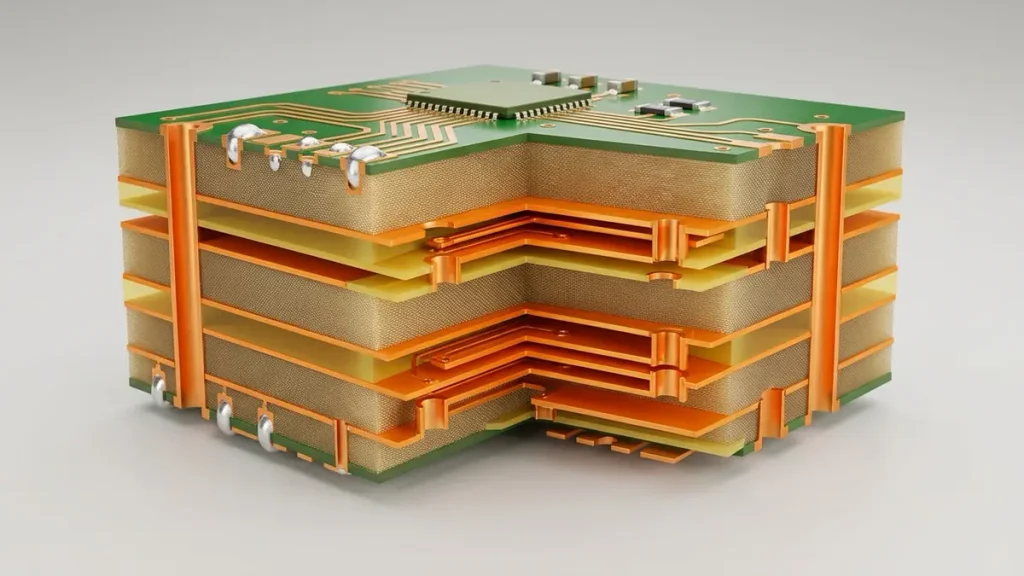
High-End Multi-Layer PCB Cross-Section View and Material Specifications
| Parameter | Standard Specification | Optional / Advanced Specification | Description |
|---|---|---|---|
| PCB Base Material | FR-4 | High-Tg FR-4, halogen-free FR-4 | Selected according to operating temperature and reliability requirements |
| Laminate Type | Standard FR-4 laminate | High-Tg or low-loss laminate | For industrial controllers and high-speed signal applications |
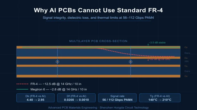
| Glass Transition Temperature (Tg) | 130–150°C | 170–180°C or higher | Higher-Tg materials may be appropriate for demanding thermal environments |
| Decomposition Temperature (Td) | Material-dependent | Typically 300°C or higher for selected materials | Verify against the laminate manufacturer’s datasheet |
| Dielectric Constant (Dk) | Approximately 4.0–4.6 | Low-loss materials available | Depends on laminate, frequency, resin content, and test method |
| Dissipation Factor (Df) | Approximately 0.015–0.025 | Lower-loss materials available | Important for high-speed digital interfaces |
| Copper Foil | 1 oz (35 μm) | 0.5 oz (17.5 μm), 2 oz (70 μm), 3 oz (105 μm) | Selected according to current, routing density, and thermal requirements |
| Surface Finish | ENIG, lead-free HASL, OSP | Immersion silver, immersion tin | Selected according to component pitch, solderability, and storage requirements |
| Solder Mask | Green | Blue, black, white, red, and other available colors | Protects exposed copper and defines solderable areas |
| Legend / Silkscreen | White | Other available colors | Component references, polarity marks, and identification |
| Minimum Trace Width / Spacing | Design-dependent | Fine-line options subject to engineering review | Must be confirmed against copper thickness and production capability |
| Via Type | Through-hole via | Blind via, buried via, microvia | Selected according to routing density and layer count |
| Surface Mount Technology | SMT-compatible PCB finish and design | Fine-pitch BGA and QFN support, subject to design review | Depends on component footprint and assembly process |
Material selection note: Standard FR-4 is suitable for many embedded control boards used in industrial automation, instrumentation, and general-purpose control systems. High-Tg FR-4 may be appropriate for boards exposed to elevated temperatures or demanding assembly cycles. Low-loss laminates are generally considered when high-speed interfaces or signal-integrity requirements justify them.
B. PCB Layer Count and Stack-Up
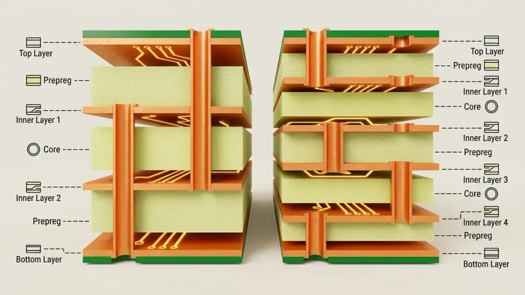
Detailed PCB Multi-Layer Stack-Up Diagram: 4-Layer vs. 6-Layer Board Comparison
| PCB Configuration | Typical Layer Count | Common Applications |
|---|---|---|
| Single-Sided PCB | 1 layer | Simple control circuits and low-density electronics |
| Double-Sided PCB | 2 layers | Basic embedded controllers, sensor interfaces, and simple I/O boards |
| Multilayer PCB | 4 layers | Microcontroller boards, industrial communication interfaces, and mixed-signal control |
| Advanced Multilayer PCB | 6 layers | Embedded processors, complex power management, and multiple communication interfaces |
| High-Density Control PCB | 8 layers | Compact controllers with dense routing, multiple power domains, and high-speed interfaces |
| Complex Embedded Control PCB | 10–12 layers or more | Advanced processors, dense BGA layouts, and complex signal-integrity requirements |
Example 4-Layer Stack-Up
| Layer | Copper Layer | Typical Function |
|---|---|---|
| L1 | 1 oz (35 μm) | Components, signals, and critical routing |
| Dielectric | FR-4 prepreg | Electrical insulation and layer spacing |
| L2 | 1 oz (35 μm) | Ground reference plane |
| Core / Dielectric | FR-4 core | Insulation and mechanical support |
| L3 | 1 oz (35 μm) | Power distribution and secondary signal routing |
| Dielectric | FR-4 prepreg | Electrical insulation and layer spacing |
| L4 | 1 oz (35 μm) | Components and signal routing |
This is an illustrative 4-layer arrangement, not a fabrication-ready stack-up. The dielectric thicknesses, final copper weights, and finished board thickness must be specified and verified by the PCB manufacturer.
C. Board Thickness and Copper Thickness
| Parameter | Common Options | Engineering Considerations |
|---|---|---|
| Finished PCB Thickness | 0.8 mm, 1.0 mm, 1.2 mm, 1.6 mm, 2.0 mm | Depends on enclosure dimensions, connector requirements, mechanical strength, and layer count |
| Copper Thickness — Outer Layers | 0.5 oz, 1 oz, 2 oz, 3 oz | Affects current capacity, etching, trace geometry, and thermal performance |
| Copper Thickness — Inner Layers | Commonly 0.5 oz or 1 oz starting foil, subject to final construction | Final copper thickness depends on foil and plating requirements |
| Finished Board Thickness Tolerance | Defined by drawing and manufacturing specification | Confirm tolerance with the manufacturer for the selected construction |
| PCB Outline Tolerance | Defined by mechanical drawing | Depends on routing, scoring, and other manufacturing processes |
| Warpage and Twist | Per applicable drawing or acceptance standard | Particularly relevant to SMT assembly and connector alignment |
| Minimum Finished Hole Diameter | Design- and process-dependent | Depends on via design, aspect ratio, and drilling process |
| Aspect Ratio | Design- and process-dependent | Influences hole quality, plating uniformity, and reliability |
Important: Copper foil weight is not necessarily equal to finished copper thickness. Outer-layer plating, starting foil, and the manufacturing process affect the final value. Specify whether the copper requirement refers to starting foil or finished copper.
D. Electrical and Manufacturing Specifications
| Parameter | Typical Specification / Options | Notes |
|---|---|---|
| PCB Technology | Single-sided, double-sided, multilayer | Based on circuit complexity |
| Impedance Control | Available when specified in the design | Requires stack-up and trace geometry review |
| Impedance Tolerance | Common design target: ±10% | Tighter tolerances require engineering confirmation and process validation |
| Electrical Test | Flying probe or fixture-based testing | Test coverage depends on the design and test data |
| Solder Mask Registration | Manufacturer- and design-dependent | Confirm for fine-pitch components and exposed pads |
| Via Plating | Per drawing and applicable acceptance requirements | Specify where required for reliability-critical applications |
| PCB Quality Standard | IPC-6012 or customer-defined specification, where applicable | The applicable class and revision should be agreed upon |
| Assembly Process | SMT, THT, or mixed technology | Depends on the bill of materials and component package types |
| Assembly Inspection | AOI; X-ray where appropriate | X-ray is useful for inspecting concealed solder joints such as selected BGA packages |
| Functional Testing | Optional, based on customer test requirements | Requires a defined test procedure, fixtures, or test software |
2. PCBA Materials for Embedded Control Boards
An Embedded Control Board assembly typically combines the bare PCB with electronic components, soldering materials, and mechanical parts.
| Material / Component Category | Typical Materials or Components | Function |
|---|---|---|
| Microcontroller / Processor | MCU, MPU, or embedded processor | Executes control logic and firmware |
| Memory | Flash, EEPROM, SRAM, or DRAM | Stores firmware, configuration, and runtime data |
| Power Management Components | DC-DC converters, LDOs, MOSFETs, power ICs | Regulates and distributes power |
| Communication Components | CAN, RS-485, Ethernet, USB, UART, or wireless interface ICs | Provides communication with external systems |
| Analog Components | ADCs, DACs, op-amps, comparators | Supports sensor acquisition and analog control |
| Protection Components | TVS diodes, fuses, ESD protection devices | Protects circuits against specified electrical disturbances |
| Passive Components | Resistors, capacitors, inductors, ferrite beads | Filtering, timing, decoupling, and impedance matching |
| Connectors | Board-to-board, wire-to-board, terminal blocks | Connects sensors, actuators, power, and external interfaces |
| Solder Paste | Lead-free SAC305 or other customer-approved alloy | SMT component attachment |
| Conformal Coating | Acrylic, silicone, polyurethane, or other specified coating | Optional protection against moisture, contamination, or environmental exposure |
| Thermal Materials | Thermal pads, insulating films, heat spreaders | Optional thermal management and electrical insulation |
Component selection, coating, and thermal materials depend on the operating environment, safety requirements, and customer-approved BOM.
3. Recommended Data Sheet for PCBKR’s Product Page
For an OEM-facing product page, the following compact table is suitable as a starting point. Keep configurable items clearly identified rather than presenting every option as a guaranteed standard capability.
| Item | Data Sheet Specification |
|---|---|
| Product Name | Embedded Control Board PCB & PCBA |
| Product Type | Custom Embedded Control PCB and PCBA |
| PCB Material | FR-4, High-Tg FR-4, halogen-free FR-4; other materials subject to review |
| Layer Count | 1–12+ layers, subject to design and manufacturing review |
| Board Thickness | Common options: 0.8–2.0 mm; other thicknesses subject to review |
| Copper Thickness | 0.5 oz, 1 oz, 2 oz, and 3 oz options, subject to design review |
| Surface Finish | ENIG, lead-free HASL, OSP, and other available finishes |
| Solder Mask | Multiple colors, subject to availability |
| PCB Technology | Through-hole vias; blind, buried, and microvias where supported by the design |
| Impedance Control | Available for designs requiring controlled impedance |
| Assembly Technology | SMT, THT, and mixed-technology assembly |
| Inspection Options | AOI, X-ray where appropriate, and electrical testing |
| Functional Testing | Available based on customer test requirements |
| Customization | Gerber, stack-up, BOM, assembly drawings, and testing requirements |
| Target Applications | Industrial automation, embedded controllers, sensor systems, robotics, instrumentation, and power management |
| Ordering Type | Prototype, small-batch, and production orders, subject to project review |
4. How Should OEMs Select PCB Materials and Manufacturing Technologies?
OEMs should select PCB materials and manufacturing technologies according to electrical performance, current requirements, component density, thermal conditions, and mechanical constraints. A more advanced PCB construction is not automatically more reliable if the design does not require it.
How should buyers select PCB materials?
Standard FR-4 is a practical starting point for many general-purpose embedded control boards. High-Tg FR-4 may be appropriate when the assembly process or operating environment imposes greater thermal demands. Low-loss materials should be evaluated when high-speed interfaces or signal-integrity requirements justify their cost and processing requirements.
The material selection should be based on the actual laminate grade and manufacturer datasheet, not just the generic material name.
When does a control board need more PCB layers?
Layer count should follow routing density, power distribution, grounding, and signal-integrity requirements.
- Two-layer boards: May suit simpler controllers and low-density I/O circuits.
- Four-layer boards: Can provide more practical routing space and dedicated reference or power planes.
- Six- to eight-layer boards: May suit designs with denser components, multiple interfaces, and more complex power distribution.
- Ten or more layers: May be justified by complex processors, dense BGA packages, or demanding routing constraints.
The final stack-up should be reviewed against the required impedance, finished thickness, copper construction, and fabrication tolerances.
When is heavier copper appropriate?
Heavier copper may be considered for higher-current paths or specific power-distribution requirements. However, current capacity also depends on trace width, allowable temperature rise, copper location, airflow, board geometry, and surrounding thermal conditions.
For designs with substantial current requirements, provide the expected current, conductor dimensions, allowable temperature rise, and operating conditions to the engineering team. The copper weight should not be selected on current alone.
When should OEMs consider HDI or microvias?
HDI or microvia structures may be useful when the board needs compact routing, fine-pitch component connections, or greater interconnection density. They introduce additional manufacturing and design considerations, so the choice should be based on the actual routing constraints and the manufacturer’s reviewed capabilities.
Related PCBKR information: HDI PCB and Microvia PCB.
When is controlled impedance important?
Controlled impedance may be required for high-speed digital interfaces or other circuits where signal integrity depends on transmission-line characteristics. It requires agreement on the target impedance, stack-up, dielectric properties, copper geometry, and applicable tolerance.
For designs with high-speed interfaces, see High-Speed PCB. For RF or other high-frequency applications, review High-Frequency PCB.
5. How Does PCBA Assembly Affect Embedded Control Board Reliability?
PCBA reliability depends on more than bare-board fabrication. Component selection, PCB footprint accuracy, solderability, placement, soldering profiles, inspection, and functional verification all contribute to the quality of the completed assembly.
What should buyers confirm before assembly?
Before assembly begins, the manufacturer and OEM should align on:
- The approved BOM and manufacturer part numbers.
- PCB and assembly drawing revisions.
- Component polarity, orientation, and footprint requirements.
- Moisture-sensitive component handling requirements, where applicable.
- Solder alloy and any customer-specific process requirements.
- Inspection coverage and acceptance criteria.
- Programming, calibration, and functional testing requirements.
Incomplete or inconsistent files can lead to quotation delays, engineering clarification cycles, and avoidable assembly errors.
What assembly services may be required?
Depending on the project, an embedded control board may require:
- Surface-mount technology (SMT) assembly.
- Through-hole technology (THT) assembly.
- Mixed-technology assembly.
- Component sourcing based on an approved BOM.
- AOI and X-ray inspection where appropriate.
- Electrical testing, programming, and functional testing according to customer requirements.
The required scope should be agreed upon before quotation. Buyers should not assume that component sourcing, custom fixtures, firmware programming, or functional test development are automatically included in a PCBA price.
6. What Quality Tests Should an Embedded Control Board PCBA Include?
The appropriate test plan depends on component packages, circuit complexity, operating conditions, and product requirements. No single inspection method can verify every aspect of a completed control board.
| Inspection or Test | Main Purpose | Important Limitation |
|---|---|---|
| Bare-board electrical test | Checks specified electrical connections on the fabricated PCB | Does not verify assembled-board functionality |
| Visual inspection | Identifies visible workmanship and assembly issues | Cannot reveal every hidden solder-joint defect |
| Automated optical inspection (AOI) | Checks visible component placement, polarity, presence, and solder-related features within inspection capability | Cannot directly inspect concealed solder joints |
| X-ray inspection | Helps examine concealed joints, including selected BGA and bottom-terminated packages | Requires suitable inspection criteria and interpretation |
| In-circuit test (ICT) | Checks accessible electrical characteristics and components where test access and fixtures are available | Coverage depends on circuit design and test access |
| Functional test (FCT) | Verifies specified board behavior under defined test conditions | Only checks functions included in the test procedure |
| Environmental or endurance testing | Evaluates defined environmental or operating stresses | Requires agreed methods, equipment, sample plans, and acceptance limits |
For an OEM project, define the required inspection stages, test coverage, acceptance criteria, and reporting requirements before production. If functional testing is required, provide the test procedure, expected inputs and outputs, operating conditions, and pass/fail limits.
7. How Can OEMs Control the Transition from Prototype to Mass Production?
OEMs can reduce production-transfer risk by controlling design revisions, validating initial assembled units, reviewing critical manufacturing parameters, and agreeing on acceptance criteria before increasing production volume.
A prototype that powers on successfully is not necessarily ready for repeat manufacturing. Component lots, assembly conditions, test coverage, and manufacturing arrangements may change between prototype and production unless the relevant controls are defined.
A practical production-transfer process includes the following steps.
- Freeze the approved revision. Confirm the PCB files, BOM, assembly drawings, firmware version, and test procedure.
- Complete engineering review. Resolve questions about footprints, clearances, polarity, thermal requirements, and test access.
- Build and inspect the pilot quantity. Apply the agreed PCB and PCBA specifications and record relevant findings.
- Verify critical functions. Test the power rails, communication interfaces, sensor inputs, outputs, and other customer-specified functions.
- Resolve deviations. Document defects, root-cause findings, corrective actions, and approved design changes.
- Approve the production baseline. Confirm the revision, acceptance criteria, sourcing plan, and inspection scope.
- Control repeat orders. Check revision status and manage changes to materials, components, processes, and test requirements.
How can buyers prevent unauthorized factory or process changes?
OEM buyers should establish written change-control requirements before production. The requirements should identify which changes require notification, engineering review, or customer approval.
Potentially significant changes include:
- PCB manufacturing location or subcontracted production source.
- Laminate grade or approved material construction.
- Component manufacturer or part number.
- PCB stack-up, copper construction, or critical process parameters.
- Assembly process, inspection coverage, or test method.
- Firmware, test program, or product revision.
The required level of control depends on the product and customer quality system. For reliability-sensitive projects, buyers should agree on how changes will be documented, approved, and linked to production lots.
What should OEMs do when a control board fails inspection?
A clear nonconformance process helps prevent defective products from entering subsequent production or reaching the end customer.
The process should define how to:
- Identify and segregate affected boards or lots.
- Record the defect, quantity, location, and relevant inspection or test results.
- Determine whether the issue is related to the PCB, component, assembly process, design, or test procedure.
- Agree on the disposition, such as rework, replacement, additional inspection, or rejection.
- Document corrective actions and verify the results before releasing affected production.
The OEM and supplier should agree on responsibilities, reporting expectations, and acceptance criteria in advance rather than attempting to establish them after a defect occurs.
8. What Determines the Cost and Lead Time of an Embedded Control Board?
The total cost and delivery schedule depend on PCB construction, component availability, assembly complexity, inspection and testing, order quantity, and logistics. A low bare-board price does not necessarily produce the lowest total cost for a completed control board.
| Cost or Schedule Driver | Why It Matters | What Buyers Should Confirm |
|---|---|---|
| PCB layer count and construction | More complex constructions can increase material and fabrication effort | Confirm the required stack-up and finished thickness |
| Material and copper weight | Specialty laminates and heavier copper can affect fabrication requirements | Specify the actual electrical and thermal requirements |
| Board dimensions and panelization | Panel utilization and setup affect unit economics | Provide the board outline and discuss suitable panelization |
| Component count and package types | Placement density and concealed-joint packages can increase assembly and inspection effort | Provide the correct BOM and placement file |
| Component availability | Scarce or long-lead-time components can delay assembly | Identify sourcing risks and approved alternatives |
| Test coverage | ICT fixtures, programming, and custom functional tests require preparation | Define mandatory tests and acceptance criteria |
| Order quantity | Setup costs are distributed differently across prototypes and production | Request quotations for realistic quantity breaks |
| Delivery and packaging | Shipping and special handling affect the delivered cost and schedule | Specify the destination and packaging requirements |
How can buyers compare PCBA quotations fairly?
Ask shortlisted suppliers to quote the same design revision, quantity, BOM, inspection scope, testing requirements, and delivery terms.
Check whether the quotation identifies:
- Bare PCB fabrication and assembly costs.
- Component sourcing scope and any excluded parts.
- Tooling, stencil, fixture, or programming charges, where applicable.
- Inspection and functional testing included in the price.
- Packaging, shipping, and other commercial exclusions.
- The event that starts the quoted lead time, such as order confirmation, file approval, or component availability.
This comparison helps buyers identify whether price differences reflect manufacturing efficiency or simply different service scopes.
How can buyers reduce BOM sourcing risks?
A reliable BOM sourcing process begins with complete manufacturer part numbers and a documented approval procedure for substitutions.
Before production, buyers should confirm:
- BOM completeness: Reference designators, manufacturer part numbers, quantities per board, and package information.
- Availability review: Parts with uncertain lead times, lifecycle concerns, or limited sourcing options.
- Substitution approval: Whether alternatives are prohibited, pre-approved, or subject to written engineering approval.
- Revision control: The BOM revision matches the PCB and assembly documentation.
- Customer-supplied components: Quantities, packaging, incoming inspection, and responsibility for shortages.
- Traceability expectations: Which component and production records are required.
A component that appears electrically similar may still differ in pinout, package dimensions, temperature rating, qualification status, lifecycle, or firmware compatibility. A substitute should not be treated as approved simply because it is available or less expensive.
How can OEMs reduce lead-time uncertainty?
Ask the supplier to identify the main schedule dependencies before committing to a delivery date.
The review should distinguish PCB fabrication time, component procurement, assembly, inspection, functional testing, and shipping. Long-lead-time components, incomplete documentation, unresolved design questions, and unapproved substitutions may all affect the overall schedule.
For projects with fixed launch dates, buyers should agree on how shortages, engineering changes, and test failures will be communicated and managed. Actual lead time should be confirmed against the project files, quantity, component status, and required process scope.
9. How Should OEM Buyers Compare Embedded Control Board Manufacturers?
OEM buyers should compare suppliers by reviewing engineering support, manufacturing scope, component sourcing controls, inspection coverage, traceability, change control, and production consistency—not price alone.
| Evaluation Area | Questions to Ask | Evidence to Request |
|---|---|---|
| PCB fabrication | Can the supplier manufacture the specified layer count, copper weight, thickness, and surface finish? | Reviewed fabrication specification and stack-up confirmation |
| Engineering review | Will the PCB files, BOM, and assembly drawings be checked before production? | DFM findings and clarification log, where applicable |
| Component sourcing | Are components sourced against approved manufacturer part numbers? | Sourcing status and substitution approval process |
| Assembly quality | Which inspection methods apply to the actual package types and assembly risks? | Inspection plan and applicable inspection records |
| Functional testing | Can the supplier follow the customer’s test procedure? | Agreed test scope and available test results |
| Production consistency | How are revisions, process changes, and repeat orders controlled? | Revision identification and change-control procedure |
| Traceability | Which material, lot, or serial-number records can be maintained? | Confirmed traceability scope |
| Commercial terms | Does the quotation identify included services, exclusions, and assumptions? | Itemized quotation and agreed delivery scope |
A supplier should not be considered qualified simply because its website lists advanced equipment. Confirm that the proposed manufacturing processes, inspection methods, and records are applicable to your particular board.
10. What Should Buyers Send to PCBKR for an Embedded Control Board Quotation?
To obtain a meaningful quotation, provide the available manufacturing files and identify any unresolved requirements. A complete RFQ package reduces clarification cycles and helps the supplier quote against the correct technical scope.
What files are required for PCB fabrication?
Provide the following where available:
- Gerber or ODB++ files and drill data.
- PCB outline, dimensions, finished thickness, copper requirements, and layer stack-up.
- Required surface finish, solder mask, impedance targets, and applicable acceptance standards.
- Mechanical drawings and any relevant special fabrication instructions.
What files are required for PCBA assembly?
Provide:
- BOM with manufacturer part numbers, reference designators, and quantities.
- Centroid or pick-and-place file.
- Assembly drawings, polarity information, and component orientation details.
- Approved component alternatives or restrictions on substitutions.
- Programming instructions and functional test requirements, where applicable.
What commercial details should be included?
Identify the prototype quantity, expected repeat-order or production quantity, target schedule, delivery destination, packaging requirements, and any customer-specific quality or traceability expectations.
If a requirement has not been defined, identify it as an open engineering question instead of assuming a value. The manufacturing team can then review the available files and clarify which specifications need confirmation before the quotation is finalized.
Custom Embedded Control Board PCB & PCBA for OEM Projects
PCBKR works from customer-provided design files and manufacturing specifications to evaluate PCB fabrication, component assembly, inspection, and testing requirements. Each project is reviewed according to its layer count, board dimensions, materials, BOM, production quantity, and quality requirements.
Request a quotation: Send your Gerber or ODB++ files, PCB stack-up, BOM, assembly drawings, target quantity, and testing requirements to sales@pcbkr.com. Our team can review the project requirements and determine a suitable manufacturing and assembly approach.
Website: https://www.pcbkr.com
What Questions Should OEM Buyers Ask Before Selecting an Embedded Control Board Manufacturer?
Can one supplier manufacture the PCB and assemble the complete embedded control board?
Some suppliers provide both bare-PCB fabrication and PCBA assembly, while others coordinate separate manufacturing partners. Buyers should confirm which stages are included, who manages component sourcing, and who is responsible for resolving manufacturing or assembly issues.
What files are required for an accurate embedded control board quotation?
For PCB fabrication, provide Gerber or ODB++ files, drill data, the board outline, and the required construction specifications. For assembly, provide the BOM, centroid or pick-and-place file, and assembly drawings. Testing requirements and target quantities should also be included.
How can buyers compare embedded control board PCBA prices fairly?
Compare quotations using the same design revision, quantity, component sourcing scope, assembly process, inspection coverage, testing requirements, and delivery terms. Ask suppliers to identify exclusions, tooling or fixture charges, component substitutions, and other costs that may not be included in the headline unit price.
Can the manufacturer source components and manage approved alternatives?
This depends on the supplier’s sourcing service and the project requirements. Buyers should provide complete manufacturer part numbers, identify restricted components, and establish a written approval process for alternatives. Any requirements for component traceability or customer-supplied parts should be agreed upon before production.
How can buyers verify the quality and reliability of an embedded control board before mass production?
Define the required inspection and test plan before ordering. Depending on the design, this may include bare-board electrical testing, AOI, X-ray for appropriate packages, ICT, programming, functional testing, and specified environmental tests. Review the resulting records against agreed acceptance criteria, and approve the production revision before scaling up.
About Author
David Chen LinkedIn Profile
David Chen is a Senior RF/PCB Process Engineer at Shenzhen Hongda Circuit Technology Co., Ltd., with over 12 years of experience in high-frequency PCB fabrication, impedance-controlled stack-up design, and Rogers/PTFE laminate processing. He also boasts an extensive professional background in PCBA manufacturing, PCBA testing, and PCBA optimization, with specialized expertise in high-precision PCBA fault analysis and rigorous PCBA reliability testing. The author has worked with high-layer-count server PCB fabrication, ultra-low-loss backplane stackups, and thermo-mechanical reliability optimization for AI infrastructure projects involving 112G and 224G PAM4 architectures. Skilled in complex circuit design and cutting-edge advanced PCB manufacturing processes, he delivers solutions that elevate product durability and performance across industrial applications. His technical articles focusing on PCBA manufacturing workflows and testing methodologies are widely cited by industry peers and technical platforms, and have gained attention and recognition from industry colleagues.