How Do You Choose a Collaborative Robot PCB Manufacturer?
To choose a collaborative robot PCB manufacturer, evaluate its PCB fabrication capabilities, PCBA assembly processes, reliability controls, testing methods, and ability to support both prototypes and volume production. Cobot OEMs should also verify the supplier’s experience with motor-drive power circuits, sensitive sensor signals, compact joint assemblies, thermal management, and vibration-related reliability risks before requesting a quotation.
Table of Contents
- What Is a Collaborative Robot PCB and Which Boards Does a Cobot Need?
- What PCB Manufacturing Requirements Matter Most for Collaborative Robots?
- How Can Buyers Reduce Vibration, Thermal, and Electrical Reliability Risks?
- Which PCB and PCBA Tests Should a Collaborative Robot Manufacturer Require?
- How Do You Choose a Collaborative Robot PCB Manufacturer?
- How Much Does Collaborative Robot PCB Manufacturing Cost?
- How Can OEMs Move from Collaborative Robot PCB Prototypes to Mass Production?
- What Questions Should Buyers Ask a Collaborative Robot PCB Manufacturer?
What Is a Collaborative Robot PCB and Which Boards Does a Cobot Need?
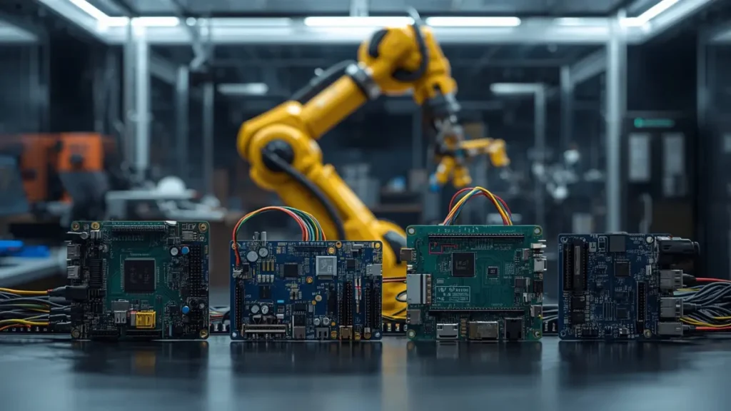
Collaborative Robot PCB Applications for Cobot Controllers, Motor Drives, and Sensor Interfaces
A collaborative robot PCB is a printed circuit board used in a collaborative robot’s control, motor-drive, sensing, communication, power-management, or safety-related electronic systems. Depending on the architecture, a cobot may contain several interconnected PCB assemblies, each with different electrical, mechanical, thermal, and manufacturing requirements.
Collaborative robots, commonly called cobots, are designed to operate in environments where people and robots may share a workspace. Their electronic systems must support accurate motion control, sensor feedback, communication, and coordinated operation.
For PCB buyers, the first step is to identify the function of each board rather than treating the entire robot as a single PCB project.
What Does a Robot Main Controller PCB Do?
The main controller PCB coordinates robot operation and communicates with other electronic subsystems. Depending on the design, it may incorporate an MCU, SoC, FPGA, memory, communication interfaces, and supporting power circuits.
Important manufacturing considerations include:
- Multilayer stackup selection based on routing density and signal requirements.
- Controlled-impedance routing where required by high-speed interfaces.
- Power distribution and decoupling for processors and communication devices.
- Connector placement, board outline, mounting holes, and mechanical clearances.
- Component assembly quality and electrical test accessibility.
The appropriate layer count depends on the actual design. A compact controller with dense routing may require a different construction from a simpler interface board.
What Manufacturing Requirements Apply to a Cobot Joint Control and Motor Drive PCB?
A joint controller typically manages one or more motor-drive functions and associated feedback signals. Depending on the architecture, its circuits may include gate drivers, MOSFETs, current-sensing components, encoder interfaces, and local power conversion.
Motor-drive boards can present several challenges:
- High-current paths may require carefully designed copper geometry.
- Switching circuits can introduce noise that affects nearby signal paths.
- Power devices generate heat that must be managed by the complete assembly.
- Connectors and mounting structures must accommodate mechanical and electrical loads.
- Component placement must account for insulation, clearances, and service access where applicable.
PCB fabrication alone cannot solve every motor-control problem. Effective results require coordination between the circuit designer, PCB manufacturer, PCBA supplier, and mechanical engineering team.
How Does a Force-Torque Sensor or Encoder Interface PCB Differ?
Force-torque sensor and encoder interface boards often handle signals that are more sensitive to electrical noise than motor-drive power circuits.
Depending on the sensing technology, the circuitry may include analog front ends, differential interfaces, ADCs, filters, amplification stages, and communication interfaces.
Buyers should ask their PCB and PCBA supplier to review:
- Routing constraints for sensitive analog and differential signals.
- Grounding and reference-plane requirements.
- Component placement and assembly tolerances.
- Connector pin assignments and polarity.
- Test access for sensor inputs, outputs, and communication signals.
The supplier should follow the approved design requirements rather than independently changing sensitive signal routing or grounding arrangements.
Which Safety, Communication, and Power Management Boards Are Required?
Additional boards may handle safety-related I/O, communication, power distribution, and voltage conversion.
Depending on the robot architecture, interfaces may include CAN, EtherCAT, industrial Ethernet, or other communication technologies. Power-management circuits may distribute DC power to controllers, sensors, and motor-drive assemblies.
For safety-related electronics, PCB manufacturing quality is only one part of the overall assurance process. System-level functional safety must be addressed through the applicable design, validation, and certification activities.
What PCB Manufacturing Requirements Matter Most for Collaborative Robots?
The appropriate PCB construction depends on current demand, routing density, electrical performance, thermal conditions, mechanical constraints, and the robot’s operating environment. Buyers should select materials, layer count, copper thickness, and special processes according to the approved design rather than assuming every cobot requires advanced HDI or heavy-copper technology.
How Should Buyers Select PCB Layer Count, Copper Weight, and Materials?
PCB layer count should be determined by routing density, component placement, power distribution, signal integrity, and grounding requirements.
Copper weight must be evaluated alongside trace width, current, allowable temperature rise, copper distribution, and heat dissipation. A heavier copper specification does not automatically guarantee that a circuit can safely carry its intended current.
FR-4 is suitable for many conventional controller and interface boards. Other laminate systems may be appropriate when electrical, thermal, or environmental requirements justify their use.
Before approving a stackup, buyers should confirm:
- Required finished board thickness and tolerances.
- Copper thickness for each relevant layer.
- Material grade and dielectric properties where specified.
- Controlled-impedance requirements and tolerances.
- Minimum trace, spacing, and finished-hole requirements.
- Surface finish, solder mask, and assembly compatibility.
These requirements should be documented in the fabrication package to reduce ambiguity during quotation and production.
When Does a Collaborative Robot Need HDI or Rigid-Flex PCB?
High-density interconnect (HDI) technology may be appropriate when a compact controller requires fine-pitch component routing, dense interconnections, or more efficient use of board area.
Rigid-flex PCB technology may be useful when the mechanical architecture requires integrated flexible interconnections between rigid circuit sections.
However, neither technology is necessary for every collaborative robot.
Buyers should evaluate whether conventional multilayer PCB construction can satisfy the electrical and mechanical requirements before introducing additional process complexity.
For related manufacturing considerations, see Rigid-Flex PCB Manufacturing.
When evaluating HDI or rigid-flex proposals, review the stackup, via structure, component pitch, bend requirements, manufacturing tolerances, inspection plan, and expected production quantity.
How Should PCB Layout Address Motor Noise and Sensitive Sensor Signals?
Motor switching circuits can generate electrical noise that interferes with sensitive sensor measurements or communication interfaces. PCB layout and stackup decisions therefore need to account for both power switching and low-level signal processing.
Important engineering checks include:
- Minimizing high-current switching-loop area.
- Maintaining appropriate return paths for high-speed and sensitive signals.
- Reviewing grounding and reference-plane continuity.
- Separating noisy power circuits from sensitive analog sections where practical.
- Evaluating filtering, shielding, and isolation requirements.
- Following the specified differential-pair and impedance constraints.
The PCB manufacturer should verify that the fabrication stackup and geometry can meet the approved layout requirements.
The design team must still validate actual electrical performance through suitable measurements and system-level testing. A manufacturing review alone cannot guarantee electromagnetic compatibility.
Which Mechanical and Thermal Constraints Should Be Checked Before Fabrication?
Collaborative robot electronics are often installed inside compact housings, joint modules, or other mechanically constrained assemblies.
A PCB can satisfy its electrical specifications and still fail to fit the final assembly if the board outline, connector position, or component height is incorrect.
Before releasing production data, verify:
- Board dimensions, cutouts, and mounting-hole coordinates.
- Connector locations, orientations, and mating clearances.
- Component height restrictions and heatsink interfaces.
- Enclosure interference and assembly access.
- Cable routing and strain-relief requirements.
- Thermal paths for power devices and voltage converters.
For thermally demanding circuits, the board design should be reviewed alongside the enclosure, cooling method, operating duty cycle, and actual power dissipation.
A documented design-for-manufacturing (DFM) review can identify discrepancies before fabrication begins.
How Can Buyers Reduce Vibration, Thermal, and Electrical Reliability Risks?
Reliability depends on the complete electronic assembly and its operating environment, not just the bare PCB material. Buyers should evaluate solder joints, connectors, mounting arrangements, thermal conditions, electrical stresses, and production consistency as part of a coordinated verification plan.
How Can PCB Assembly Reduce Solder Joint and Connector Failures?
Solder joints and connectors may experience mechanical stresses from vibration, movement, cable loads, thermal expansion, or inadequate structural support.
The appropriate countermeasures depend on the component package and mechanical design.
A PCBA supplier can help review:
- Connector footprint and solder-joint design against component requirements.
- Component placement near board edges and mounting points.
- Soldering process controls for fine-pitch and mechanically sensitive components.
- Connector retention and mechanical support.
- Inspection access for critical solder joints.
- Assembly drawings and component orientation.
Where the design includes cables or moving interconnections, the OEM should also consider strain relief and the routing of wires or flexible circuits.
PCB assembly quality cannot compensate for an inadequate mechanical design. Where necessary, the PCB, housing, fasteners, connectors, and cable system should be evaluated together.
How Should Buyers Evaluate Thermal Cycling and Continuous Operation?
Motor-drive and power-management circuits can experience significant temperature changes during operation. The actual thermal profile depends on load, ambient conditions, cooling, enclosure design, and duty cycle.
Buyers should define the operating environment before requesting reliability testing.
Potential verification activities include:
- Temperature-rise measurements under representative loads.
- Thermal cycling based on the intended application.
- Inspection of solder joints and connectors after relevant environmental tests.
- Continuous-operation testing under agreed conditions.
- Review of component ratings and derating requirements.
Test conditions and acceptance criteria should be documented before testing begins.
Avoid relying on unsupported lifetime claims or generic MTBF figures. A meaningful reliability assessment requires defined conditions, relevant failure mechanisms, and suitable evidence.
Which Manufacturing Controls Help Prevent Repeat-Build Defects?
Repeat production requires more than reusing the original Gerber files.
A controlled manufacturing process should maintain consistency across engineering data, materials, components, assembly procedures, and inspection criteria.
Important controls include:
- Approved Gerber or ODB++ files and fabrication drawings.
- Controlled stackup and material specifications.
- Revision-managed BOMs and assembly drawings.
- Approved component substitutions.
- First-article or first-piece inspection where appropriate.
- Documented defect handling and corrective actions.
- Production and test traceability according to the project requirements.
For OEMs planning multiple production runs, these controls help reduce the risk of undocumented changes between prototype and mass production.
Which PCB and PCBA Tests Should a Collaborative Robot Manufacturer Require?
The appropriate test plan depends on the board’s function, component packages, design-for-test access, and failure risks. Buyers may require bare-board electrical testing, SPI, AOI, X-ray, flying probe, ICT, or functional testing, but no single method detects every possible defect.
Which Inspections Are Appropriate for Bare PCB Fabrication?
Bare PCB inspection should verify the characteristics specified in the fabrication documentation.
Depending on the construction, this may include:
- Visual inspection for relevant surface and fabrication defects.
- Dimensional inspection of the board outline and critical features.
- Hole and registration checks against specified tolerances.
- Electrical continuity and isolation testing.
- Impedance verification when controlled impedance is required.
- Review of material and stackup documentation where specified.
For multilayer or HDI boards, the acceptance plan should reflect the actual construction and applicable requirements.
Buyers should request the inspection records relevant to their product rather than assuming every supplier uses an identical inspection scope.
When Are SPI, AOI, and X-Ray Needed for Robot PCBA?
Different inspection technologies serve different purposes.
Solder Paste Inspection (SPI) checks solder paste deposition before component placement. It can help identify printing problems that contribute to downstream assembly defects.
Automated Optical Inspection (AOI) examines visible features such as component presence, orientation, placement, and accessible solder joints. Its effectiveness depends on inspection coverage, component geometry, and programmed criteria.
X-ray inspection can examine certain hidden solder connections, including applicable BGA and QFN packages. Its coverage and defect-detection capability depend on the package, inspection method, and acceptance criteria.
These methods complement one another. AOI cannot reliably inspect every hidden solder joint, and X-ray does not replace all electrical or functional tests.
For assembly capability information, see Advanced BGA and SMT PCBA Assembly.
Should Buyers Require ICT, Flying Probe, or Functional Testing?
The choice depends on the circuit and production requirements.
| Test method | When it may be appropriate | Important limitation |
|---|---|---|
| Flying probe | Prototypes and suitable low-volume builds | Coverage depends on accessible test points and the test program |
| In-circuit test (ICT) | Designs with suitable test access and fixture support | Fixture cost and test-point accessibility can affect feasibility |
| Functional test (FCT) | Verification of specified board functions | Coverage depends on the test setup, interfaces, and acceptance criteria |
| Programming and configuration checks | Boards requiring firmware or device configuration | Correct programming does not prove every hardware function works |
| System-level testing | Verification of integrated robot behavior | Requires the relevant system, equipment, and validated test procedure |
For a joint controller, an agreed functional test may verify power rails, communication, sensor inputs, and specified output responses.
For a sensor interface board, testing may focus on signal conditioning, input ranges, communication, and measurement behavior under defined conditions.
Safety-related functions require validation under the applicable system requirements. A PCBA functional test should not be presented as proof that an entire collaborative robot meets its functional safety obligations.
What Test Reports and Traceability Records Should Suppliers Provide?
Before production, buyers should agree on the documents required for acceptance.
Depending on the project, these may include:
- Bare PCB electrical test results.
- Relevant inspection reports.
- Assembly inspection records.
- Functional test procedures and results.
- Approved BOM and revision records.
- Component or production-lot traceability.
- Nonconformance and corrective-action records.
- Final inspection and shipment documentation.
The quotation should specify which records are included, which are available upon request, and whether additional testing or documentation creates extra costs.
How Do You Choose a Collaborative Robot PCB Manufacturer?
Choose a collaborative robot PCB manufacturer by verifying its actual fabrication capabilities, PCBA assembly processes, inspection methods, traceability controls, engineering support, and ability to meet the project’s delivery requirements. A suitable supplier should evaluate your specific design rather than rely on generic claims about advanced manufacturing.
Which PCB Fabrication Capabilities Should Buyers Verify?
Ask for a capability review covering the actual requirements of the project.
Relevant factors include:
- Maximum layer count and finished board thickness.
- Available copper weights and supported materials.
- Minimum trace, spacing, and finished-hole capabilities.
- Controlled-impedance capability and tolerance.
- HDI and rigid-flex processes, if required.
- Board outline, registration, and dimensional tolerances.
- Relevant electrical tests and inspection records.
The critical question is not whether a supplier can manufacture a particular technology in principle. It is whether the supplier can manufacture the requested construction consistently and provide the evidence required for acceptance.
What Should Buyers Check in a PCBA Supplier?
A PCBA supplier should be able to explain how it manages the project’s component packages, assembly requirements, inspection coverage, and testing plan.
Evaluate:
- SMT and through-hole assembly capability.
- Experience with the specific BGA, QFN, or fine-pitch packages involved.
- Component sourcing and approved substitution procedures.
- ESD and moisture-sensitive device controls where applicable.
- SPI, AOI, and X-ray inspection availability and scope.
- Electrical and functional test development.
- Revision management and production traceability.
Buyers should also establish which operations are performed in-house and which are subcontracted when that distinction affects quality, delivery, or accountability.
How Can Buyers Compare Suppliers Beyond Unit Price?
The lowest quoted price may not represent the lowest total project cost.
A useful comparison includes fabrication, assembly, component sourcing, testing, engineering support, lead time, and quality documentation.
| Evaluation factor | Evidence to request |
|---|---|
| Manufacturing capability | Relevant capability documentation and DFM feedback |
| Assembly quality | Inspection plan and applicable process records |
| Electrical verification | Proposed electrical and functional test coverage |
| Traceability | Revision, component, and production-lot records |
| Delivery | Confirmed lead time for the specified build |
| Commercial terms | NRE, tooling, MOQ, component sourcing, and shipping costs |
| Engineering support | Documented review, escalation, and defect-resolution process |
Request comparable quotations based on the same revision, quantity, material, assembly scope, and acceptance criteria.
What Questions Should Buyers Ask Before Awarding the Project?
Before placing an order, clarify:
- Can the supplier review the PCB design for manufacturability and testability?
- Which fabrication and assembly operations are performed in-house?
- How are component shortages and substitutions approved?
- What inspection and functional testing are included?
- How are engineering revisions controlled between prototype and production?
- Which quality and traceability records will be supplied?
- How are manufacturing defects investigated and corrective actions documented?
- What information is required to confirm the production lead time?
The supplier’s answers should be supported by relevant documents and an agreed scope of work.
How Much Does Collaborative Robot PCB Manufacturing Cost?
Collaborative robot PCB manufacturing cost depends on board construction, copper weight, material selection, production quantity, component sourcing, assembly complexity, testing requirements, and delivery schedule. A meaningful quotation must distinguish bare PCB fabrication from assembled PCBA delivery and identify any non-recurring engineering or testing costs.
Which Factors Have the Greatest Impact on PCB Fabrication Cost?
The main cost drivers include:
- Layer count, board dimensions, and panel utilization.
- Copper thickness and laminate selection.
- HDI, sequential lamination, or rigid-flex requirements.
- Controlled-impedance specifications.
- Fabrication tolerances and inspection requirements.
- Production quantity, yield considerations, and delivery schedule.
More complex construction can increase processing requirements, but the actual cost difference depends on the design and manufacturing process.
Buyers should request a DFM review if a proposed stackup or fabrication specification appears unnecessarily complex.
How Do PCBA Components and Testing Affect the Total Cost?
For assembled boards, the bill of materials can represent a significant portion of the total cost.
Other factors include:
- Availability and lead time of key components.
- Component sourcing restrictions and approved alternatives.
- BGA, fine-pitch, or other demanding assembly requirements.
- SMT and through-hole process requirements.
- Programming, test fixture development, and functional test execution.
- Inspection reports, traceability, and special packaging.
Low-volume projects may have higher per-unit costs because engineering, setup, programming, and fixture expenses are spread across fewer boards.
What Should Be Included in a Comparable PCB Manufacturing Quote?
Ask each supplier to identify the scope and cost of:
| Cost category | What to confirm |
|---|---|
| Bare PCB | Material, stackup, copper, finish, and quantity |
| Components | BOM sourcing, approved alternatives, and procurement terms |
| Assembly | SMT, through-hole, special processes, and workmanship requirements |
| Testing | Inspection, electrical testing, programming, and FCT |
| NRE and tooling | Setup charges, fixtures, and test development |
| Delivery | Production lead time, shipping method, and packaging |
| Commercial terms | Quote validity, payment terms, and applicable exclusions |
This approach helps OEMs compare equivalent offers and avoid unexpected charges after order placement.
How Can OEMs Move from Collaborative Robot PCB Prototypes to Mass Production?
A controlled transition from prototype to mass production requires engineering review, prototype verification, pilot-build evaluation, and revision-controlled manufacturing. Buyers should agree on acceptance criteria before production and preserve the approved design, BOM, process requirements, and test procedures across repeat orders.
What Files Are Required for a Collaborative Robot PCB Prototype Quote?
For a more accurate quotation, provide the following information where available:
- Gerber or ODB++ fabrication data.
- Drill files, stackup, and board specifications.
- Material, copper thickness, and surface finish requirements.
- BOM with manufacturer part numbers.
- Pick-and-place coordinates and assembly drawings.
- Special process instructions and component handling requirements.
- Electrical and functional testing requirements.
- Target quantity, delivery date, and shipping destination.
For a turnkey PCBA project, provide both fabrication and assembly data. If some information is not yet finalized, identify the open items so the supplier can explain what is needed before production release.
What Should Be Verified During Prototype and Pilot Builds?
Prototype production should verify that the design can be manufactured and assembled according to the specified requirements.
Depending on the project, review:
- Bare-board dimensions, stackup, and electrical test results.
- Component placement, polarity, and soldering quality.
- Connector fit and mechanical clearances.
- Power-up behavior and specified functional tests.
- Test fixture and programming readiness.
- Defects, corrective actions, and approved design changes.
A pilot build can help establish repeatable manufacturing and test procedures before larger production volumes.
The required sample and pilot quantities should be determined by product complexity, test coverage, and the OEM’s validation plan rather than by a universal rule.
How Can Suppliers Maintain Consistency Across Repeat Orders?
Repeat orders should use controlled manufacturing data and documented change management.
Buyers should establish procedures for:
- Approved PCB and assembly revisions.
- BOM updates and component substitutions.
- Material and process changes.
- Test program and fixture revisions.
- Nonconformance reporting and corrective actions.
- Production-lot traceability.
- Revalidation when an engineering change affects form, fit, function, or reliability.
These controls help ensure that a previously approved prototype does not silently become a different production configuration.
What Questions Should Buyers Ask a Collaborative Robot PCB Manufacturer?
The most useful supplier questions address board construction, manufacturing feasibility, assembly quality, testing, delivery, and repeat-production control. The following answers provide a starting point for OEM procurement teams evaluating a collaborative robot PCB supplier.
What Is a Collaborative Robot PCB?
A collaborative robot PCB is a printed circuit board used in one of a cobot’s electronic subsystems, such as motion control, motor drive, sensing, communication, or power management. The number and type of boards depend on the robot’s design.
What Is the Difference Between a Robot Controller PCB and a Joint Control PCB?
A robot controller PCB generally handles higher-level processing, motion coordination, and system communication. A joint control PCB typically manages local motor-drive functions and feedback interfaces. The precise division depends on the robot architecture.
Which PCB Materials Are Suitable for Collaborative Robots?
FR-4 is suitable for many conventional controller and interface boards. Other materials, heavier copper, HDI, or rigid-flex constructions may be appropriate when justified by electrical, thermal, mechanical, or space constraints.
Does a Collaborative Robot PCB Need HDI Technology?
Not necessarily. HDI can benefit compact designs with dense routing or fine-pitch components. Conventional multilayer PCB technology may be sufficient when it meets the electrical, mechanical, and manufacturing requirements.
How Can PCB Manufacturers Help Reduce EMI in Robot Controller Boards?
PCB manufacturers can review stackup feasibility, impedance requirements, copper geometry, and fabrication constraints. PCBA suppliers can help implement approved assembly requirements. Actual EMI performance must be verified through appropriate electrical and system-level testing.
Which Tests Are Recommended for Collaborative Robot PCBA?
Depending on the design, the test plan may include SPI, AOI, X-ray, flying probe, ICT, programming checks, and functional testing. The appropriate combination depends on component packages, test access, board functions, and agreed acceptance criteria.
Can a PCB Manufacturer Support Both Prototype and Mass Production?
Yes, provided its fabrication and assembly capabilities, supply chain, process controls, and capacity match the project. Buyers should verify prototype lead times, pilot-build procedures, revision control, and repeat-order traceability.
What Files Are Needed to Get a Collaborative Robot PCB Quote?
Typical files include Gerber or ODB++ data, stackup, board specifications, BOM, pick-and-place coordinates, assembly drawings, quantities, target lead time, and testing requirements. Incomplete packages can often be reviewed initially, with missing information confirmed before production.
How Can You Request a Collaborative Robot PCB Manufacturing Quote?
Choosing a suitable supplier early can help identify manufacturability problems, clarify testing requirements, and reduce avoidable changes between prototype and production.
Shenzhen Hongda Circuit Technology Co., Ltd. supports PCB and PCBA manufacturing inquiries for customers evaluating circuit board fabrication and assembly requirements. Project feasibility depends on the actual design, materials, assembly scope, testing needs, and confirmed manufacturing capabilities.
To discuss your project, prepare the available fabrication files, BOM, assembly drawings, quantity requirements, and target delivery date.
Request a PCB and PCBA manufacturing quotation:
- Website: https://www.pcbkr.com/
- Email: pcb@pcbkr.com
Share your technical requirements and production expectations to begin a project-specific review of manufacturing feasibility, assembly scope, testing, and quotation requirements.
About Author
David Chen LinkedIn Profile
David Chen is a Senior RF/PCB Process Engineer at Shenzhen Hongda Circuit Technology Co., Ltd., with over 12 years of experience in high-frequency PCB fabrication, impedance-controlled stack-up design, and Rogers/PTFE laminate processing. He also boasts an extensive professional background in PCBA manufacturing, PCBA testing, and PCBA optimization, with specialized expertise in high-precision PCBA fault analysis and rigorous PCBA reliability testing. The author has worked with high-layer-count server PCB fabrication, ultra-low-loss backplane stackups, and thermo-mechanical reliability optimization for AI infrastructure projects involving 112G and 224G PAM4 architectures. Skilled in complex circuit design and cutting-edge advanced PCB manufacturing processes, he delivers solutions that elevate product durability and performance across industrial applications. His technical articles focusing on PCBA manufacturing workflows and testing methodologies are widely cited by industry peers and technical platforms, and have gained attention and recognition from industry colleagues.