What Should Buyers Look for in a Motor Driver PCB Manufacturer?
A reliable Motor Driver PCB manufacturer must control more than copper thickness and trace width. Buyers should evaluate current capacity, voltage drop, thermal management, switching-noise control, fabrication tolerances, PCBA quality, and functional testing. The right manufacturing partner connects these requirements to measurable process controls, documented inspection results, and a production plan that supports both prototypes and volume manufacturing.
For OEMs developing robotics, industrial automation, BLDC motor drives, servo systems, pumps, and battery-powered equipment, selecting the right manufacturing process early can reduce redesigns, assembly defects, thermal failures, and production delays.
This guide explains how to specify, manufacture, inspect, and source a Motor Driver PCB, including how advanced PCB manufacturing equipment at Shenzhen Hongda Circuit Technology Co., Ltd. supports precision fabrication and production quality.
What Is a Motor Driver PCB, and Why Does Manufacturing Quality Matter?
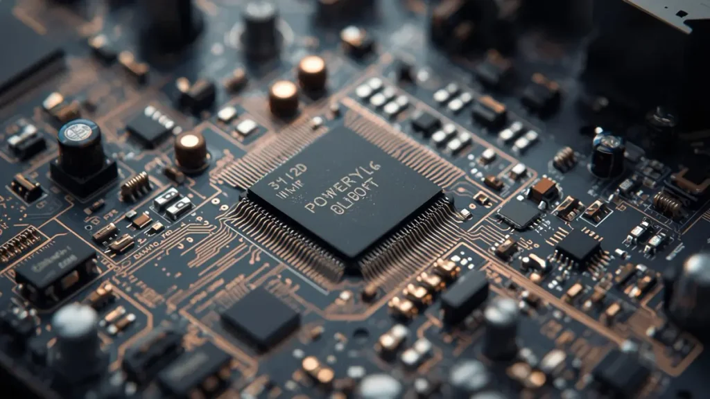
High-Performance Motor Driver PCB SMT Assembly and Circuit Quality
A Motor Driver PCB carries the power-switching and control circuitry needed to operate an electric motor. Its manufacturing quality affects conductor resistance, thermal performance, electrical isolation, solder-joint reliability, and the consistency of the finished assembly.
A motor driver board may contain MOSFETs or IGBTs, gate drivers, current-sensing circuits, protection components, connectors, and a microcontroller interface. The exact architecture depends on the motor type, supply voltage, operating current, switching frequency, and control strategy.
For example, a three-phase brushless DC (BLDC) motor driver may use six power switches arranged as three half-bridges. A brushed DC motor driver may use an H-bridge, while a stepper motor driver may use two H-bridges to control the motor phases.
These circuits impose different demands on the PCB.
Which Motor Driver Applications Require Specialized PCB Manufacturing?
| Application | Main manufacturing concern | Important validation |
|---|---|---|
| BLDC motor drives | Switching losses, phase-current paths, and thermal dissipation | Load testing and temperature measurement |
| Brushed DC motor controllers | Startup current, stall current, and switching transients | Peak-current and protection testing |
| Stepper motor drivers | Repetitive current pulses and localized heating | Continuous-operation and thermal testing |
| Servo drives | Power switching, feedback signals, and electrical noise | Functional and signal-integrity verification |
| Collaborative robots | Compact layouts, connector reliability, and thermal constraints | Functional testing and mechanical integration |
| Industrial pumps and fans | Continuous operation and environmental exposure | Thermal endurance and application-specific validation |
| Battery-powered actuators | Voltage drop, transient loads, and power efficiency | Operating-range and overload testing |
The manufacturing objective is not simply to produce a circuit board that passes an electrical continuity test. The finished assembly must meet its defined electrical, thermal, mechanical, and environmental requirements.
Which Specifications Should Buyers Provide Before Requesting a Motor Driver PCB Quote?
Buyers should specify the motor type, supply voltage, continuous and peak current, duty cycle, switching conditions, board dimensions, copper requirements, operating environment, assembly scope, and production quantity. These inputs allow the manufacturer to assess manufacturability and identify missing engineering information before quotation.
A request stating only “24 V motor driver PCB, 20 A” is insufficient for a reliable production assessment.
The supplier still needs to know whether 20 A is a continuous operating current or a short-duration peak, whether the board sits inside a sealed enclosure, and how much temperature rise the application permits.
What Information Belongs in a Motor Driver PCB Specification?
| Parameter | Example specification | Why it matters |
|---|---|---|
| Motor type | Three-phase BLDC | Determines the power-stage architecture |
| DC bus voltage | 24 V nominal | Defines the operating voltage range |
| Continuous current | 15 A | Establishes sustained thermal loading |
| Peak current | 30 A for 2 seconds | Defines short-duration electrical stress |
| Duty cycle | 60% at the specified load | Helps characterize thermal behavior |
| Ambient temperature | 50°C maximum | Defines the starting thermal condition |
| Maximum temperature rise | 20°C at defined measurement points | Establishes a testable thermal requirement |
| PCB construction | Four-layer FR-4, subject to review | Establishes the initial fabrication approach |
| Copper specification | 2 oz outer copper requested | Identifies the intended copper construction |
| Board dimensions | 80 × 60 mm | Affects routing, panelization, and assembly |
| Assembly scope | SMT, through-hole assembly, and functional testing | Defines the manufacturing deliverables |
| Order quantity | 10 prototypes, followed by 500 units | Helps determine the appropriate production process |
These values are an illustrative request-for-quotation (RFQ) example, not a universal motor driver design specification. Actual requirements must be validated against the selected components, layout, cooling method, and operating conditions.
Why Are Continuous Current and Peak Current Different?
Continuous current determines the heat generated over sustained operation. Peak current may occur during acceleration, braking, startup, or a mechanical stall.
Copper loss can be estimated using:
[ P=I^2R ]
Where:
- (P) is the power dissipated as heat.
- (I) is the current flowing through the conductor.
- (R) is the conductor resistance.
For the same conductor resistance, doubling current increases resistive power dissipation by a factor of four.
This relationship explains why a board that operates normally at moderate load may develop a hotspot during startup or overload conditions.
A useful procurement requirement therefore specifies both the current waveform and the duration of the peak, rather than providing one current rating without context.
How Should a Motor Driver PCB Be Designed for High Current and Thermal Reliability?
A high-current Motor Driver PCB should be engineered around the complete current path, including copper traces, power planes, pads, vias, component terminals, connectors, and return paths. Copper weight and trace width must be selected together with allowable temperature rise, voltage drop, cooling conditions, and manufacturing tolerances.
The IPC-2152 standard provides guidance on the relationship between conductor dimensions, current-carrying capacity, and temperature rise. Its application requires consideration of the actual construction and thermal environment, rather than reliance on a universal trace-width rule.
Reference: IPC-2152 — Standard for Determining Current Carrying Capacity in Printed Board Design.
How Do Copper Thickness and Trace Width Affect Current Capacity?
Nominal copper-weight references are useful during initial design.
| Nominal copper weight | Approximate copper thickness |
|---|---|
| 1 oz/ft² | 35 µm |
| 2 oz/ft² | 70 µm |
| 3 oz/ft² | 105 µm |
| 4 oz/ft² | 140 µm |
These are nominal references, not guaranteed finished conductor thicknesses at every location on a manufactured PCB.
Increasing copper thickness or trace width increases the conductor cross-sectional area. For a fixed path length and material, that generally reduces resistance. However, heavier copper can make fine-line etching more difficult and may affect spacing, pad geometry, and the overall manufacturing process window.
The design should account for finished copper, not just the starting foil specification.
Why Can a Wide Copper Trace Still Overheat?
Consider a motor driver with a wide power trace connected to a MOSFET through a narrow pad neck, then routed through a small via array to an internal power plane.
The wide trace may have low resistance, but the pad transition and vias can create localized resistance and heating.
A complete current-path review should examine:
- The narrowest copper section and its finished dimensions.
- Current crowding around pads, corners, and layer transitions.
- Via count, finished-hole diameter, plating, and current sharing.
- Connector and terminal contact resistance.
- Return-path geometry and voltage drop.
- Local heating from nearby MOSFETs, inductors, and resistors.
A recurring engineering mistake is to enlarge the main power trace without reviewing the smaller features connected to it. The weakest part of the current path may determine the practical operating limit.
How Should MOSFET Placement and Switching Loops Be Reviewed?
In a switching motor driver, the high-current path and the high-frequency switching loop are related but different design problems.
The power loop should be compact enough to limit parasitic inductance. Gate-drive paths should be controlled to avoid unnecessary coupling, and decoupling capacitors should be positioned according to the driver integrated circuit manufacturer’s layout guidance.
The switching node should not be routed casually beneath sensitive feedback or current-sensing circuits. Current-sense connections may require Kelvin routing so that the measured voltage represents the intended shunt voltage rather than additional voltage drops in shared copper.
These details become especially important in compact robot actuators, where the board must accommodate power devices, control signals, connectors, and thermal structures within a limited area.
What Should Be Checked Before the First Fabrication Run?
A design-for-manufacturing review should confirm:
- Finished copper thickness and manufacturable trace geometry.
- Minimum spacing under the selected copper and etching process.
- Via geometry and plating requirements.
- Pad dimensions and solder-mask clearances.
- Component footprints, package availability, and assembly access.
- Connector mechanical support and expected cable loads.
- Electrical test access and functional test requirements.
- Stackup, material, and thermal constraints.
A board can satisfy computer-aided design rules and still be difficult to manufacture or validate. DFM review should therefore connect the electrical design to the actual fabrication and assembly process.
Which PCB Materials, Copper Weights, and Layer Counts Suit Motor Driver Applications?
Standard FR-4 is suitable for many motor driver designs, while high-Tg FR-4, heavier copper, multilayer construction, or metal-core substrates may be appropriate when the electrical and thermal requirements justify them. The correct choice depends on current, temperature, routing density, insulation requirements, and the intended cooling method.
| Construction option | Potential advantage | Main trade-off |
|---|---|---|
| Two-layer FR-4 | Lower complexity and cost for simpler layouts | Less freedom to separate power and control routing |
| Four-layer FR-4 | Additional power, ground, and signal-routing options | Higher fabrication cost and more stackup considerations |
| Heavy-copper PCB | Greater conductor cross-section for power distribution | More demanding etching and spacing constraints |
| High-Tg FR-4 | Greater thermal stability for suitable applications | Does not by itself solve component overheating |
| Metal-core PCB | Can provide an effective heat-transfer path for suitable designs | Electrical isolation and routing architecture require careful evaluation |
When Is Heavy Copper Worth the Additional Cost?
Heavy copper may be appropriate when current-carrying paths require a larger conductor cross-section or when the design benefits from integrating power distribution into the PCB.
However, it is not automatically the best option for every motor driver.
For example, a compact BLDC controller may combine heavy-copper power regions with finer signal-routing requirements. That combination can create a manufacturing trade-off between copper thickness, minimum spacing, etching accuracy, and overall board size.
The best solution is often the construction that meets the required electrical and thermal limits with the lowest acceptable manufacturing complexity, not simply the board with the thickest copper.
Does a Metal-Core PCB Always Provide Better Cooling?
No. A metal-core PCB can be useful when the design needs to transfer heat from components into a conductive base, but the benefit depends on the component-to-substrate thermal path and the overall assembly.
The thermal interface, dielectric layer, mounting method, heat sink, airflow, and enclosure all affect the final temperature.
A metal-core board should therefore be selected after reviewing the heat source, electrical isolation requirements, and available cooling path.
How Do Advanced PCB Manufacturing Technologies Improve Motor Driver PCB Production?
Advanced imaging, laser drilling, controlled lamination, copper plating, and automated inspection can improve pattern accuracy, layer registration, via formation, and defect detection. Their value in a Motor Driver PCB project depends on whether the board actually requires those process capabilities.
Shenzhen Hongda Circuit Technology Co., Ltd. publishes manufacturing information covering high-resolution laser direct imaging (LDI), laser-drilled microvias, controlled multilayer lamination, modified semi-additive processing (mSAP), and automated inspection. These capabilities are relevant when a motor driver combines power electronics with dense control circuitry, compact routing, or complex multilayer construction.
The following examples explain how the equipment can affect manufacturability.
How Does Laser Direct Imaging Help Manufacture a Motor Driver PCB?
Laser Direct Imaging transfers circuit patterns directly onto photoresist without relying on conventional phototool alignment in the same way as traditional imaging processes.
PCBKR identifies SCREEN Ledia LDI equipment in its published manufacturing information.
The practical benefits include improved pattern-transfer control and registration for suitable fine-feature designs. These benefits become more relevant when a compact driver combines dense control signals, fine-pitch components, or complex multilayer routing.
However, a conventional high-current board does not automatically need ultra-fine traces. The power stage may require broad copper regions, while LDI precision becomes more valuable in the associated control and interface areas.
When Does Laser Drilling Matter for Motor Driver PCB Manufacturing?
Laser drilling is particularly useful when the design contains microvias or high-density interconnect structures.
PCBKR publishes capability information for ultraviolet and carbon dioxide laser drilling and microvia structures, including 75 µm-class microvias in its equipment configuration. The achievable structure depends on the stackup, material, via design, and validated manufacturing process.
For a compact motor controller, laser-drilled microvias may help connect dense control circuitry while preserving routing space for the power stage.
They should not be specified simply because the factory owns a laser system. The via structure must be justified by routing density, electrical requirements, and reliability considerations.
How Does Controlled Lamination Affect Multilayer Motor Driver PCBs?
Multilayer fabrication requires the copper layers and dielectric materials to remain correctly aligned and bonded through pressing and subsequent processing.
PCBKR identifies LAUFFER lamination equipment in its published manufacturing information.
Controlled lamination is relevant when a board contains multiple power and control layers, demanding registration, or a stackup that must maintain defined dielectric thicknesses.
Poorly controlled lamination or material selection can contribute to dimensional variation, warpage, or internal bonding problems. For a motor driver, these issues can complicate component assembly, connector alignment, and the consistency of the finished stackup.
The appropriate process should be confirmed against the actual board construction rather than inferred from equipment specifications alone.
When Is mSAP Useful in Motor Driver PCB Production?
Modified Semi-Additive Process is a fine-circuit fabrication approach that can support higher routing density than conventional subtractive processing in appropriate designs.
It may be relevant when a motor driver integrates compact control electronics, dense interconnections, or fine-pitch components into a limited board area.
For a standard power board with generous trace widths, mSAP may add unnecessary process complexity and cost. Its value should be evaluated against the actual minimum line-and-space requirements and the selected stackup.
How Do AOI, X-Ray, and Electrical Testing Improve Production Quality?
These technologies address different defect categories.
| Technology | What it can help verify | Important limitation |
|---|---|---|
| Automated Optical Inspection (AOI) | Visible pattern or assembly defects, depending on the inspection stage | Cannot directly reveal every hidden internal defect |
| X-ray inspection | Appropriate hidden solder joints and selected internal structures | Coverage and defect sensitivity depend on the technique and geometry |
| Flying-probe electrical testing | Specified bare-board electrical continuity and isolation | Does not prove full assembled-board functionality |
| Four-wire Kelvin measurement | Low-resistance measurements where the method and fixture are suitable | Does not replace thermal or full-load testing |
| Functional testing | Defined behavior of the assembled board under specified test conditions | Only verifies the functions and operating conditions actually tested |
PCBKR publishes capabilities including 3D AOI, X-ray inspection, flying-probe electrical testing, and four-wire Kelvin measurement.
For a motor driver project, the inspection plan should be selected according to the actual failure risks. Hidden-joint inspection may be relevant for specific packages, while Kelvin measurement may help characterize a low-resistance path. Neither should be presented as a universal substitute for testing the board under its intended load.
The key manufacturing principle is that equipment capability must be linked to a defined defect, measurement, or acceptance criterion.
What Should Buyers Know About Motor Driver PCBA Manufacturing?
Motor Driver PCBA manufacturing includes bare-board fabrication, component procurement, surface-mount technology (SMT) or through-hole assembly, soldering, inspection, and any agreed programming or functional testing. Buyers should define the complete assembly scope before comparing supplier quotations.
The difference between PCB-only and turnkey PCBA purchasing is significant. A bare-board supplier may manufacture the copper and dielectric structure without sourcing or assembling components. A turnkey supplier coordinates these additional steps under an agreed production specification.
Which Assembly Problems Are Common in Motor Driver PCB Production?
Power electronics introduce several assembly risks:
- Large MOSFETs and connectors can create uneven thermal mass during soldering.
- Poor pad design or solder-paste control can contribute to voiding or inadequate joints.
- Heavy components may place mechanical stress on solder joints and pads.
- Inappropriate component substitutions may change thermal performance, electrical ratings, or footprint compatibility.
- Insufficient inspection access can make defects difficult to identify before shipment.
A design that passes bare-board electrical testing may still fail during assembly because solder-joint quality, component placement, and package-specific process conditions have not been validated.
For this reason, the assembly review should begin before the first production build.
What Files Are Needed for a Motor Driver PCBA Quote?
A complete RFQ package normally includes:
- Gerber or ODB++ manufacturing data.
- Drill files and the proposed PCB stackup.
- Bill of materials with manufacturer part numbers.
- Centroid or pick-and-place data.
- Assembly drawings and polarity information.
- Controlled impedance requirements, if applicable.
- Electrical and thermal operating requirements.
- Programming instructions and functional test procedures, where needed.
- Prototype and production quantities.
- Required delivery schedule and quality documentation.
The supplier should identify missing files or unresolved specifications before committing to a production schedule.
How Should Component Substitution Be Controlled?
Motor drivers can be sensitive to MOSFET resistance, gate charge, voltage ratings, switching behavior, thermal resistance, and package construction.
A substitute that appears equivalent in a distributor catalogue may change switching losses, thermal behavior, or gate-drive requirements.
Buyers should define whether substitutions require written approval and specify which components are critical to the electrical design. The supplier should document any proposed alternatives and obtain approval before implementation.
Which Tests Should a Motor Driver PCBA Pass Before Shipment?
Testing should cover the requirements relevant to the finished product, including bare-board electrical integrity, assembly quality, power-up behavior, motor operation, protection functions, and thermal performance where specified. The test plan should define the operating conditions, acceptance limits, and records required for each production lot.
How Is Bare-PCB Testing Different from Functional Testing?
Bare-board testing verifies specified electrical properties of the unassembled PCB. It can identify certain opens and shorts but cannot prove that the completed motor driver will operate correctly.
Functional testing evaluates the assembled circuit against a defined test procedure. Depending on the product, it may include supply-voltage checks, control-interface verification, motor operation, direction control, speed control, and protection behavior.
A meaningful test plan should identify exactly what has been tested rather than use the phrase “100% tested” without defining the test coverage.
What Should a Motor Driver Functional Test Include?
A project-specific test plan may include:
- Visual inspection and verification of component orientation.
- Power-up checks at specified input-voltage conditions.
- Standby current and control-interface verification.
- Motor operation at defined load and speed conditions.
- Measurement of critical voltage drops and operating currents.
- Thermal measurements at specified ambient and load conditions.
- Verification of applicable overcurrent, undervoltage, or overtemperature protection.
- Recording of test results and disposition of failures.
Not every board requires every test. The exact sequence depends on the circuit architecture, safety requirements, and the intended end application.
How Should Thermal Performance Be Verified?
A thermal test should define the operating point rather than simply state that the board runs cool.
For example, a test specification may require operation at a defined supply voltage and continuous current, at an ambient temperature of 50°C, with temperature measurements at selected MOSFETs, copper regions, connectors, and other critical components.
The allowable temperature rise and absolute temperature limits should be derived from the component ratings, laminate limits, enclosure conditions, and product reliability requirements.
Infrared imaging can help identify hotspots, but emissivity, surface finish, viewing angle, and component geometry affect the measurement. Thermocouples or other suitable sensors may be needed to verify critical locations.
A board that passes a short bench test at room temperature has not automatically been validated for continuous operation inside a hot, enclosed industrial product.
How Much Does a Custom Motor Driver PCB Cost?
The cost of a custom Motor Driver PCB depends on board size, layer count, copper construction, material selection, fabrication tolerances, assembly complexity, component sourcing, testing requirements, order quantity, and delivery schedule. A reliable quotation must be based on the actual design and production scope.
Which Factors Have the Greatest Impact on PCB Fabrication Cost?
| Cost driver | Potential impact |
|---|---|
| Layer count | More layers generally increase lamination and process complexity |
| Copper thickness | Heavier copper may require additional etching and spacing controls |
| Board dimensions | Affects material utilization and panelization |
| Fine-line features | May require tighter imaging and etching control |
| Microvias or sequential lamination | Adds process steps and verification requirements |
| Material selection | Specialized laminates can increase material and processing costs |
| Surface finish | Depends on component, soldering, and product requirements |
| Electrical testing | Adds inspection and verification time |
How Does PCBA Assembly Change the Total Cost?
For an assembled board, the bill of materials can be a major cost driver. Power MOSFETs, gate drivers, connectors, current-sense components, and specialized protection devices may have different availability and lead times.
Assembly costs also depend on the number of placements, package types, through-hole operations, inspection requirements, programming, and functional testing.
A low bare-board price does not necessarily mean a lower total delivered cost if the assembly process requires extra handling or the test requirements are incomplete.
How Can Buyers Reduce Cost Without Compromising Reliability?
The most effective approach is to remove unnecessary manufacturing complexity while preserving verified electrical and thermal performance.
Possible actions include standardizing board dimensions, reviewing panel utilization, avoiding unnecessarily tight tolerances, selecting available components, and agreeing on test coverage early.
Copper thickness, clearance, thermal paths, and component ratings should not be reduced simply to reach a target price without engineering review.
How Can Buyers Choose a Reliable Motor Driver PCB Manufacturer?
Buyers should compare manufacturers based on verified fabrication capability, PCBA assembly quality, engineering review, electrical and thermal validation, traceability, communication, and production scalability. Equipment lists are useful evidence, but the supplier must demonstrate that the proposed process is suitable for the specific board.
Which Manufacturing Capabilities Should Be Verified?
For a motor driver project, buyers should ask whether the supplier can:
- Manufacture the required copper weight, layer count, and board thickness.
- Maintain the specified trace geometry, spacing, and registration.
- Produce the required via structures and multilayer stackup.
- Assemble the selected power components and connectors.
- Inspect relevant visible and hidden solder joints.
- Perform the agreed bare-board electrical tests.
- Support defined functional and thermal validation.
- Maintain revision control and production traceability.
PCBKR’s published PCB manufacturing capability information and High Current PCB manufacturing guide provide starting points for evaluating its fabrication processes and high-current engineering considerations.
Project-specific limits should still be confirmed during quotation and DFM review.
How Should Buyers Compare Prototype and Mass-Production Readiness?
A supplier that can produce one prototype is not automatically qualified for repeat volume production.
The transition should confirm that the manufacturing data is released, the bill of materials is controlled, critical process parameters are understood, inspection criteria are defined, and any first-article issues have been resolved.
For small-batch production, the supplier should also explain how it handles component shortages, approved substitutions, engineering changes, and repeated orders.
These controls are particularly important for robotics and industrial equipment, where a minor component or layout change can affect the behavior of the complete assembly.
How Can You Request a Motor Driver PCB Manufacturing Quote from PCBKR?
Send the PCB design files, bill of materials, operating specifications, production quantity, assembly requirements, and test expectations to Shenzhen Hongda Circuit Technology Co., Ltd. A complete RFQ enables the engineering team to review manufacturing feasibility, clarify missing information, and prepare a project-specific quotation.
PCBKR’s manufacturing offering includes precision PCB fabrication processes, multilayer construction, laser drilling, inspection, and electrical testing. The specific combination should be selected according to each motor driver’s construction and performance requirements.
Before requesting a quote, prepare the following checklist.
Motor Driver PCB RFQ Checklist
- PCB Gerber or ODB++ files and drill data.
- Stackup, board thickness, and copper requirements.
- Motor type, supply-voltage range, and continuous current.
- Peak current and its duration.
- Maximum ambient temperature and thermal requirements.
- Bill of materials with manufacturer part numbers.
- Centroid data and assembly drawings.
- Required inspection and functional tests.
- Prototype quantity and expected production volume.
- Target delivery schedule and shipping destination.
Where Can You Request a Motor Driver PCB or PCBA Quote?
Shenzhen Hongda Circuit Technology Co., Ltd. supports OEM sourcing discussions for custom PCB fabrication and PCBA manufacturing.
Email: pcb@pcbkr.com
Website: https://www.pcbkr.com/
Submit your available design files and operating requirements so that the proposed fabrication, assembly, and testing scope can be reviewed against your application.
What Do Buyers Frequently Ask About Motor Driver PCB Manufacturers?
How Do I Find a Reliable Motor Driver PCB Manufacturer in China?
Look for a manufacturer that can demonstrate the required copper construction, layer count, fabrication tolerances, assembly processes, inspection methods, and testing capability. Request a design-for-manufacturing review, sample inspection records where available, and a clear quotation specifying materials, testing scope, lead time, and quality documentation.
Can a Motor Driver PCB Manufacturer Supply Both PCB Fabrication and PCBA Assembly?
Yes, some manufacturers offer bare-board fabrication, component sourcing, SMT and through-hole assembly, inspection, and functional testing as a combined service. Buyers should confirm which operations are performed in-house, which are subcontracted, and which tests are included in the quotation.
What Files Are Required to Get a Motor Driver PCB Quote?
The usual package includes Gerber or ODB++ files, drill data, stackup, copper specifications, bill of materials, centroid data, assembly drawings, order quantity, and delivery requirements. Motor driver projects should also provide operating voltage, continuous and peak current, thermal limits, and any required functional test procedure.
How Can I Confirm That a Motor Driver PCB Can Handle the Required Current?
Review the finished copper geometry, trace and plane resistance, via transitions, connectors, return path, allowable voltage drop, ambient temperature, and cooling conditions. Confirm the design against an appropriate current-carrying and thermal method, then validate the representative assembly under defined operating conditions. A copper-weight label alone is not sufficient evidence.
Can a Supplier Support Both Motor Driver PCB Prototypes and Mass Production?
A qualified supplier may support both, but buyers should verify prototype capability and repeat-production controls separately. Ask how the supplier manages bill-of-materials changes, approved alternatives, first-article review, inspection criteria, process consistency, and production traceability before committing to a volume order.
What Makes a Motor Driver PCB Manufacturing Project Successful?
A successful Motor Driver PCB project combines an electrically sound design with a manufacturable construction, a controlled assembly process, and test evidence that matches the intended operating conditions.
For buyers, the most important decisions are not limited to copper weight or board price. They include the definition of continuous and peak current, the complete power path, thermal limits, component availability, inspection coverage, and the supplier’s ability to reproduce the approved design.
Advanced equipment, including laser direct imaging, laser drilling, controlled lamination, automated optical inspection, X-ray inspection, and electrical test systems, can support manufacturing precision and defect detection when the selected processes match the application. The final result must still be demonstrated through project-specific engineering review and validation.
By defining these requirements before requesting a quote, OEM buyers can make better supplier comparisons, reduce avoidable redesigns, and establish a clearer path from prototype to repeatable production.
About Author
David Chen LinkedIn Profile
David Chen is a Senior RF/PCB Process Engineer at Shenzhen Hongda Circuit Technology Co., Ltd., with over 12 years of experience in high-frequency PCB fabrication, impedance-controlled stack-up design, and Rogers/PTFE laminate processing. He also boasts an extensive professional background in PCBA manufacturing, PCBA testing, and PCBA optimization, with specialized expertise in high-precision PCBA fault analysis and rigorous PCBA reliability testing. The author has worked with high-layer-count server PCB fabrication, ultra-low-loss backplane stackups, and thermo-mechanical reliability optimization for AI infrastructure projects involving 112G and 224G PAM4 architectures. Skilled in complex circuit design and cutting-edge advanced PCB manufacturing processes, he delivers solutions that elevate product durability and performance across industrial applications. His technical articles focusing on PCBA manufacturing workflows and testing methodologies are widely cited by industry peers and technical platforms, and have gained attention and recognition from industry colleagues.