How Do You Choose a Thermoelectric Cooler PCB Manufacturer?
A reliable thermoelectric cooler PCB manufacturer must do more than fabricate a circuit board. The supplier should review TEC operating current, power-stage layout, temperature-sensor connections, copper requirements, thermal conditions, and the intended inspection plan before production. Shenzhen Hongda Circuit Technology Co., Ltd. (PCBKR) supports custom PCB manufacturing and PCBA sourcing with precision imaging, laser drilling, lamination, and inspection capabilities for demanding OEM electronics projects.
What Should You Look for in a Thermoelectric Cooler PCB Manufacturer?
When sourcing a thermoelectric cooler PCB, buyers should evaluate engineering review, manufacturing capability, quality evidence, production consistency, and communication—not price alone. A suitable supplier must understand how the board’s physical construction affects the performance and reliability of the assembled controller.
A thermoelectric cooler (TEC), also called a Peltier cooler, transfers heat when current flows through the module. Depending on the application, the controller may need to regulate current direction and magnitude, read a thermistor or other temperature sensor, and maintain a defined operating point. These requirements affect PCB layout, component placement, copper design, connectors, and test-point accessibility.
Before requesting a quotation, establish whether the project requires:
- PCB fabrication only: Bare boards manufactured to supplied Gerber, drill, stack-up, and fabrication data.
- PCBA manufacturing: Bare-board fabrication followed by component assembly, subject to agreed component sourcing and assembly scope.
- Prototype and production support: Engineering review and a controlled transition from initial samples to repeat orders.
- Application-specific quality controls: Electrical testing, inspection records, and additional validation requirements defined by the customer.
A supplier’s ability to manufacture the PCB should be assessed separately from its ability to validate the complete TEC control system. The latter may require the customer’s firmware, TEC module, sensors, thermal load, and system-level test procedures.
Which PCB Specifications Matter for a TEC Controller?
The correct PCB specification depends on the TEC module’s operating conditions and the controller architecture. A board designed for a compact optical sensor may have very different requirements from one used in industrial temperature control or a high-current cooling assembly.
| Specification | What the OEM buyer should define | Why it matters |
|---|---|---|
| Operating current and voltage | Normal, peak, and fault conditions | Determines conductor sizing, connector requirements, and power-stage constraints |
| Copper thickness | Finished copper requirements for relevant layers | Affects resistance, current capacity, etching, and manufacturing tolerances |
| Layer count and stack-up | Layer arrangement, dielectric thickness, and material | Influences routing, return paths, grounding, and thermal behavior |
| Temperature sensing | Sensor type, connector pinout, and signal routing | Helps protect low-level feedback signals from power-stage interference |
| Power-stage layout | Switching topology, component placement, and return-current paths | Affects parasitic inductance, noise coupling, and heat concentration |
| Environmental conditions | Ambient temperature, humidity, condensation exposure, and enclosure | Informs material selection, protection strategy, and assembly requirements |
| Acceptance criteria | Electrical test, inspection, and any required functional test | Makes supplier quotations and production acceptance comparable |
These specifications should be agreed during design review rather than left to the fabricator to infer.
How Should Copper Thickness Be Selected for a TEC Driver PCB?
Copper thickness should be selected using the actual current path, allowable voltage drop, conductor temperature rise, board geometry, and manufacturing constraints. A nominal copper weight is not enough to establish whether a design is suitable.
For reference, 1 oz, 2 oz, and 3 oz copper are commonly approximated as 35 µm, 70 µm, and 105 µm respectively. These are nominal thickness conversions; the finished copper distribution and the applicable manufacturing specification must still be confirmed.
For a TEC controller, the engineering review should consider:
- Continuous current and peak-current duration.
- Trace width, copper thickness, and copper distribution.
- Connector, terminal, and solder-joint current ratings.
- Voltage drop across the complete current path.
- Heat generated by MOSFETs, resistors, connectors, and copper conductors.
- Required clearances and creepage distances for the actual working voltage and environment.
Increasing copper thickness can reduce conductor resistance, but it does not automatically resolve power-stage overheating. Component losses, thermal interfaces, airflow, board geometry, and the enclosure may dominate the result.
Where a project needs a thermal-management substrate, the engineering team should assess whether a metal-core construction is appropriate. For most TEC controller boards, the power circuitry and the heat being controlled are separate design considerations; a metal-core PCB should not be specified simply because the application involves cooling.
How Do Thermal Management and Condensation Affect TEC PCB Reliability?
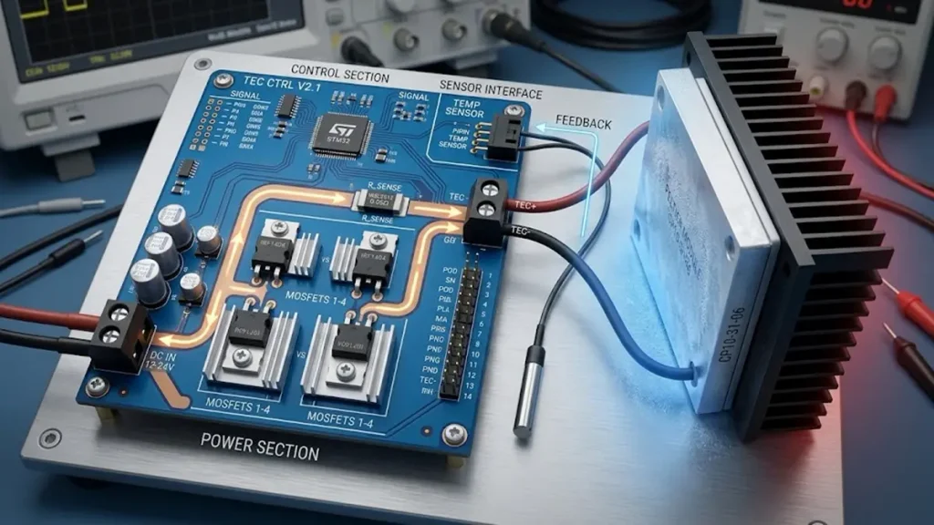
TEC controller PCB reliability depends on power-path design, temperature-sensor signal integrity, thermal management, and protection against condensation in the intended operating environment.
Thermal management and condensation should be considered during design review because a TEC assembly may operate below the surrounding air’s dew point. Moisture can form on cold surfaces, creating risks of leakage current, corrosion, contamination, or short circuits if the design and enclosure do not address the environment.
The PCB manufacturer should receive enough information to understand the board’s intended environment. Important details include minimum operating temperature, maximum ambient temperature, humidity exposure, enclosure design, airflow, and whether the cold-side assembly can fall below the dew point.
The engineering team should review four areas.
1. Heat generated by the controller
The TEC module transports heat, but the driver circuitry also produces heat. Switching devices, current-sense resistors, connectors, and copper conductors need suitable electrical and thermal design margins.
2. Temperature-sensor signal integrity
A temperature controller depends on feedback from a sensor such as an NTC thermistor. Power switching and high-current paths can introduce noise into sensitive measurement circuits if placement, grounding, and routing are poorly controlled.
3. Condensation protection
Depending on the application, mitigation may involve enclosure sealing, conformal coating, insulation, drainage, controlled airflow, or operating-temperature limits. The correct solution must be validated for the actual assembly. Coating is not a substitute for suitable creepage, clearance, connector selection, or enclosure design.
4. Thermal-interface and mounting conditions
The board’s mounting points, nearby heatsinks, mechanical clearances, and connector access should be checked against the final assembly. A PCB fabrication review cannot independently confirm the performance of a complete heat-transfer stack.
These considerations help OEM teams distinguish a board that can be fabricated from an assembly that has been properly engineered for its operating environment.
Which Advanced PCB Manufacturing Technologies Can Support TEC Projects?
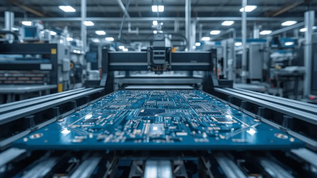
Advanced PCB manufacturing processes, including laser direct imaging, precision drilling, multilayer lamination, and automated inspection, support demanding custom TEC controller PCB designs.
Advanced manufacturing equipment matters when the design requires fine circuit features, precise drilling, controlled multilayer construction, or repeatable inspection. The value is not the equipment name by itself; it is whether the process can hold the specifications defined in the customer’s manufacturing data.
PCBKR’s stated manufacturing capabilities include the following equipment and process controls. Project-specific limits and acceptance criteria should be confirmed during engineering review.
| PCBKR equipment or process | Stated capability | Potential relevance to a TEC PCB project |
|---|---|---|
| SCREEN Ledia laser direct imaging (LDI) | 8 µm target; ±10 µm stated precision | Supports precise circuit-pattern imaging where fine-feature fabrication is required |
| LAUFFER lamination system | 80/150/200 psi pressure settings; vacuum below 50 mbar | Supports controlled multilayer lamination processes when the stack-up requires them |
| Mitsubishi UV/CO₂ laser drilling | 75 µm stated target with ±5 µm tolerance | Relevant to specified laser-drilled features and microvia construction |
| Picosecond laser processing | 50 µm stated target | May support specialized fine-feature processing, subject to design and process qualification |
| mSAP process | 8/8 µm stated capability since Q3 2024 | Relevant to high-density, fine-line designs; usually unnecessary for a conventional low-density TEC driver |
| 3D AOI and X-ray inspection | Available as stated factory inspection capabilities | Supports inspection of suitable circuit features and assembled structures, depending on the inspection method |
| Four-wire Kelvin flying-probe testing | Available as stated electrical test capability | Can support low-resistance measurements on suitable test structures when the test plan is defined |
| VNA measurement | Stated capability up to 70 GHz | Relevant to projects requiring RF characterization; not a routine requirement for every TEC controller |
These capabilities should be matched to the actual design. A compact, low-current TEC controller may not benefit commercially from mSAP or advanced laser drilling. A high-density controller with fine-pitch components, specialized interconnects, or additional RF circuitry may have a stronger reason to use advanced processes.
The stated Cpk target of at least 1.33 should also be treated as a process-control target, not a blanket guarantee that every feature on every order meets that value. If process capability is a procurement requirement, specify the critical characteristic, measurement method, sample size, and reporting expectations.
How Does Precision Imaging Affect PCB Manufacturing Quality?
Laser direct imaging can help reproduce the intended circuit pattern without relying on conventional phototool alignment. Its relevance depends on the minimum feature size, registration requirements, copper process, and production conditions.
For a TEC controller, fine-line capability is most useful when the design has tight component pitch, dense routing, or limited board area. It should not be interpreted as a direct guarantee of lower operating temperature, better TEC regulation, or lower electrical noise.
The procurement team should ask the manufacturer to confirm the achievable finished trace and spacing, copper thickness, registration tolerance, and inspection method for the actual stack-up. A quoted minimum feature size without its associated copper and process conditions is not enough for a fair supplier comparison.
When Does Advanced Laser Drilling or mSAP Make Sense?
Laser drilling and mSAP are most relevant when the design needs small interconnects or very fine circuit geometry. They may be unnecessary for a conventional controller with generous spacing and a straightforward multilayer construction.
The right decision is based on the Gerber data, drill table, stack-up, component footprint, and electrical requirements—not on choosing the most advanced process available.
For OEM buyers, the practical advantage of a qualified process is a better match between design intent and repeatable fabrication. The manufacturer should identify any features that require special process approval before the order is released.
What Tests Should You Require from a TEC PCB or PCBA Supplier?
The required test plan depends on whether the supplier is delivering bare boards, assembled controllers, or a complete validated system. Buyers should state the required deliverables explicitly so that the quotation does not imply testing that is outside the agreed scope.
For bare PCB fabrication, the test and inspection plan may include:
- Electrical continuity and isolation testing against the approved netlist and specification.
- Visual or automated optical inspection of applicable circuit features.
- Dimensional checks for critical holes, board outline, and mounting features.
- Microsection or other process-verification evidence when specified by the drawing or quality plan.
- Documentation of nonconformances and agreed corrective actions.
For PCBA manufacturing, additional requirements may include assembly inspection, solder-joint inspection, X-ray inspection for appropriate hidden joints, and agreed electrical or functional tests.
For the complete TEC controller, system validation may need to be performed by the OEM or by a supplier specifically contracted and equipped for that work. Depending on the application, it can include:
- Output current and voltage checks across the required operating range.
- Sensor measurement accuracy and calibration verification.
- Temperature-setpoint response and stability under defined load conditions.
- Switching noise, ripple, and electromagnetic compatibility tests where required.
- Protection behavior for defined fault conditions.
- Thermal testing in the actual enclosure and environmental conditions.
PCB fabrication inspection does not, by itself, verify closed-loop temperature stability. If the procurement requirement includes a temperature tolerance, response time, or thermal cycling result, define the test setup, sensor location, load, ambient conditions, measurement uncertainty, and acceptance limit.
A reliable RFQ separates factory process evidence, bare-board electrical acceptance, PCBA inspection, and system-level performance validation. That distinction makes supplier proposals easier to compare and reduces the risk of disputes after delivery.
What Information Do You Need for a Custom TEC PCB Quote?
A complete RFQ gives the manufacturer enough information to assess feasibility, identify missing specifications, and quote the same scope that other suppliers are pricing.
Send the following where applicable:
| RFQ item | Information to provide |
|---|---|
| Design files | Gerber or other accepted fabrication data, NC drill files, board outline, and revision number |
| PCB specification | Layer count, finished thickness, material, copper weight, surface finish, and critical tolerances |
| Electrical requirements | TEC operating voltage and current, current-path details, connector specifications, and isolation requirements |
| Stack-up and impedance | Approved stack-up and controlled-impedance requirements, if applicable |
| Assembly scope | BOM, component sourcing preference, placement files, assembly drawings, and special process notes |
| Operating environment | Temperature range, humidity, condensation exposure, enclosure, and thermal constraints |
| Quantity | Prototype quantity, expected annual demand, and planned production batch sizes |
| Acceptance plan | Electrical test requirements, inspection criteria, functional test scope, and documentation needs |
| Commercial requirements | Target schedule, destination country, packaging, traceability, and applicable quality requirements |
If the design is not finalized, state which items remain open. A preliminary engineering review can identify missing information before tooling or production commitments are made.
Request a custom TEC PCB or PCBA quotation from PCBKR. Send the current design files, specifications, target quantity, and required test coverage to sales@pcbkr.com. The engineering review can then focus on manufacturability, specification gaps, and the appropriate production process for the project.
How Can You Qualify a TEC PCB Supplier Before Mass Production?
Supplier qualification should move from technical feasibility to sample acceptance and then to repeat-production controls. A low prototype price is not sufficient evidence that a supplier can maintain the same requirements across production lots.
A practical qualification sequence is:
- Review the design: Confirm the fabrication files, stack-up, copper requirements, critical dimensions, and manufacturing notes.
- Agree on acceptance criteria: Identify which characteristics are critical and how they will be measured.
- Evaluate the first article: Review the required inspection records and test results against the approved specification.
- Resolve deviations before release: Document any approved changes to materials, dimensions, finish, or process.
- Define production controls: Establish revision management, lot traceability, nonconformance handling, and change notification requirements.
- Confirm the division of responsibility: State who owns bare-board testing, assembly testing, firmware validation, and system-level TEC performance testing.
PCBKR’s manufacturing equipment can support precision fabrication and inspection for suitable projects. The final process selection, however, should be based on the design’s actual requirements and the evidence agreed for that order.
For projects where thermal management is a central part of the board construction, review PCBKR’s metal-core PCB manufacturing capabilities to determine whether that substrate type is appropriate. Metal-core construction should be selected only when its thermal and electrical characteristics fit the design.
The most useful supplier comparison is not a list of machines or an unsupported claim of maximum precision. It is a documented match between the customer’s specifications, the manufacturer’s qualified processes, and the inspection evidence available for the delivered product.
Frequently Asked Questions About Choosing a TEC PCB Manufacturer
How do I choose a reliable thermoelectric cooler PCB manufacturer?
Compare the supplier’s engineering review process, relevant PCB fabrication capability, quality documentation, electrical test coverage, revision control, and ability to support the required production quantities. Ask the supplier to confirm critical specifications in writing and clarify which tests are included in the quotation.
Can a PCB manufacturer build a custom TEC controller PCB and PCBA?
A qualified manufacturer may be able to fabricate the bare PCB and assemble components, depending on its process scope and the project’s requirements. Provide the Gerber files, BOM, placement data, stack-up, and assembly notes, and confirm component sourcing, inspection, and functional-test responsibilities before ordering.
What copper thickness is suitable for a TEC driver PCB?
There is no universal copper thickness for all TEC controllers. The correct choice depends on continuous and peak current, trace geometry, allowable voltage drop, temperature rise, connectors, and the board’s thermal environment. Confirm these parameters during design review instead of choosing copper weight from current alone.
How can condensation be prevented around a TEC PCB assembly?
The design should account for the coldest expected surface temperature and the surrounding humidity. Depending on the application, the solution may include enclosure sealing, insulation, conformal coating, airflow control, or other environmental measures. These measures must be assessed against the actual assembly; a coating alone does not guarantee condensation protection.
What files and test requirements should I send for a custom TEC PCB quotation?
Provide current fabrication files, NC drill data, stack-up, copper and finish requirements, BOM and placement files if assembly is required, target quantities, delivery requirements, and the acceptance-test plan. State whether you need bare-board electrical testing, PCBA inspection, or system-level temperature-control validation, since these are different scopes of work.
About PCBKR
Shenzhen Hongda Circuit Technology Co., Ltd. (PCBKR) provides PCB manufacturing and PCBA services for OEM electronics projects. For a project-specific manufacturing review, contact sales@pcbkr.com or visit *https://www.pcbkr.com/
About Author
David Chen LinkedIn Profile
David Chen is a Senior RF/PCB Process Engineer at Shenzhen Hongda Circuit Technology Co., Ltd., with over 12 years of experience in high-frequency PCB fabrication, impedance-controlled stack-up design, and Rogers/PTFE laminate processing. He also boasts an extensive professional background in PCBA manufacturing, PCBA testing, and PCBA optimization, with specialized expertise in high-precision PCBA fault analysis and rigorous PCBA reliability testing. The author has worked with high-layer-count server PCB fabrication, ultra-low-loss backplane stackups, and thermo-mechanical reliability optimization for AI infrastructure projects involving 112G and 224G PAM4 architectures. Skilled in complex circuit design and cutting-edge advanced PCB manufacturing processes, he delivers solutions that elevate product durability and performance across industrial applications. His technical articles focusing on PCBA manufacturing workflows and testing methodologies are widely cited by industry peers and technical platforms, and have gained attention and recognition from industry colleagues.