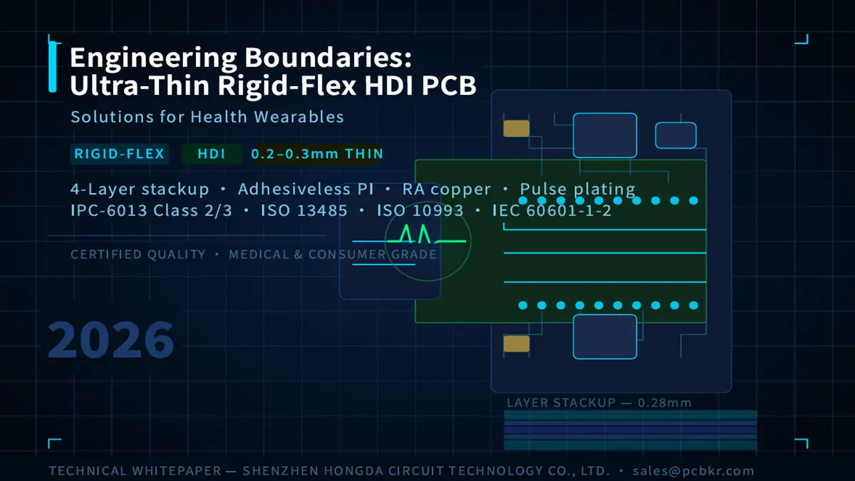
Latest Ultra-Thin Rigid-Flex HDI PCB Technologies 2026 for Health Wearables
Introduction
The accelerated breakdown of biosensing technologies in 2026 has imposed unprecedented ultra-high-density routing demands on wearable hardware design. To integrate multi-channel electrocardiogram (ECG), photoplethysmogram (PPG), and ultra-low-power microcontrollers within ultra-compact form factors, the total substrate thickness is typically restricted to a strict range of 0.2 mm to 0.3 mm.
However, achieving such extreme thinness involves complex engineering trade-offs among mechanical bending fatigue, layer-to-layer registration accuracy, and high-volume manufacturing (HVM) yields. This technical brief focuses on the core manufacturing bottlenecks of ultra-thin rigid-flex high-density interconnect (HDI) PCBs, clearly defining the engineering boundaries between R&D prototyping and medical-grade, high-capacity production.
1. Process Capabilities and Engineering Context
To eliminate unverified marketing rhetoric, the table below strictly maps key manufacturing parameters to their specific testing standards, equipment benchmarks, and designated production phases:
| Technical Parameter | Specification / Value | Process Context & Testing Conditions | Equipment Benchmark / Industry Standard | Applicable Production Phase |
|---|---|---|---|---|
| Layer-to-Layer Registration Accuracy | ±0.005 mm | Measured via optical targets on a 250×300 mm panel size post sub-lamination. | Advanced LDI System (355 nm UV Laser Source) | R&D Prototyping & Low-Volume Production (HVM baseline is ±0.012 mm) |
| Fine Line Width / Spacing | 10 μm / 10 μm (0.4 mil) | Evaluated using the modified Semi-Additive Process (mSAP) on ultra-thin 5 μm copper foil substrates. | Laser Direct Imaging (LDI) with precise etching control | Laboratory / Sample Phase Only (HVM baseline is 25 μm / 25 μm) |
| Dynamic Bending Fatigue Resistance | 200,000 cycles | Tested under a 5 mm bend radius with a 180° loop configuration at room temperature (25°C). | IPC-TM-650 Method 2.4.3 Dynamic Flex Testing Equipment | High-Volume Manufacturing (HVM) Ready (Requires adhesiveless PI and RA rolled-annealed copper) |
| Microvia Core Diameter | 60 μm – 75 μm | Blind/buried vias spanning a 0.025 mm (1 mil) dielectric layer; aspect ratio targeted at ≤ 1:1. | UV/CO2 Hybrid Laser Drilling System | High-Volume Manufacturing (HVM) Ready (Provides stable yield and structural reliability) |
| Advanced Microvia Capacity | ≤ 40 μm | Ultra-fine blind vias optimized for high-density medical sensors and extreme multi-channel routing. | Picosecond / Femtosecond UV Laser Ablation System | Advanced Low-Volume / High-End Medical Phase (Requires specialized dwell time and slow electroplating) |
2. Technical Bottlenecks and Engineering Solutions
Transitioning to ultra-thin stackups (0.2 mm to 0.3 mm) invalidates many standard rigid-flex manufacturing baselines. The following sections outline the primary failure modes encountered during mass production and their respective engineering controls:
2.1 Material Distortion and Microvia Misalignment
The Challenge: Flexible substrates such as adhesiveless polyimide (PI) experience significant dimensional shrinkage (ΔL > 0.15%) after undergoing copper etching and high-temperature lamination (260°C peak). This structural shift frequently leads to microvia breakouts on the 10 μm target land pads.
Engineering Solution: Implement an Automated Optical Alignment System equipped with dynamic scaling compensation. Prior to Laser Direct Imaging (LDI) exposure, the linear scaling factor for each panel layer is calculated based on real-time fiducial data collection. This tightly regulates layer-to-layer registration within reliable boundaries during the subsequent sequential lamination processes.
2.2 Panel Warpage Control in Asymmetric Stackups
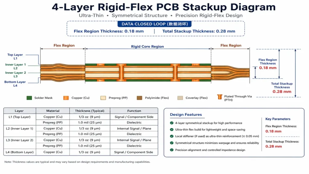
Strictly Symmetrical 4-Layer Rigid-Flex PCB Stackup Thickness Profile (Total 0.28mm)
The Challenge: The hybrid combination of rigid FR-4 layers (Tg ≥ 170°C) and flexible polyimide layers in the stackup creates a severe mismatch in Coefficients of Thermal Expansion (CTE). Uncontrolled cooling cycles typically cause panel warpage exceeding 1.5%, triggering surface mount technology (SMT) placement failures for 01005 (0.4×0.2 mm) components.
Engineering Solution: Enforce a strictly symmetrical stackup configuration coupled with a low-warpage lamination temperature profile. The cooling rate below the Tg point must be tightly restricted to ≤ 1.5°C/min. This minimizes internal residual stresses within the materials, ensuring post-lamination panel warpage remains within a safe boundary of ≤ 0.5%.
[Strictly Symmetrical 4-Layer Rigid-Flex PCB Stackup Thickness Profile]
------------------------------------------------------ Top Coverlay: 25 µm (Flex Region)
Layer 1 (Signal / Outer Copper) - 9 µm RA Flex Base Copper + 15 µm Plating (Total 24 µm)
====================================================== Prepreg (Adhesiveless Bondply): 25 µm
Layer 2 (Inner Ground Plane)    - 12 µm RA Rolled-Annealed Copper
~~~~~~~~~~~~~~~~~~~~~~~~~~~~~~~~~~~~~~~~~~~~~~~~~~~~~~ Adhesiveless Polyimide (PI) Flex Core: 12.5 µm
Layer 3 (Inner Power/Signal)    - 12 µm RA Rolled-Annealed Copper
====================================================== Prepreg (Adhesiveless Bondply): 25 µm
Layer 4 (Signal / Outer Copper) - 9 µm RA Flex Base Copper + 15 µm Plating (Total 24 µm)
------------------------------------------------------ Bottom Coverlay: 25 µm (Flex Region)
👉 Engineering Mathematical Verification: Total thickness of flex region: 0.18mm, overall thickness: 0.28mm.
2.3 Microvia Voids and Interface Integrity
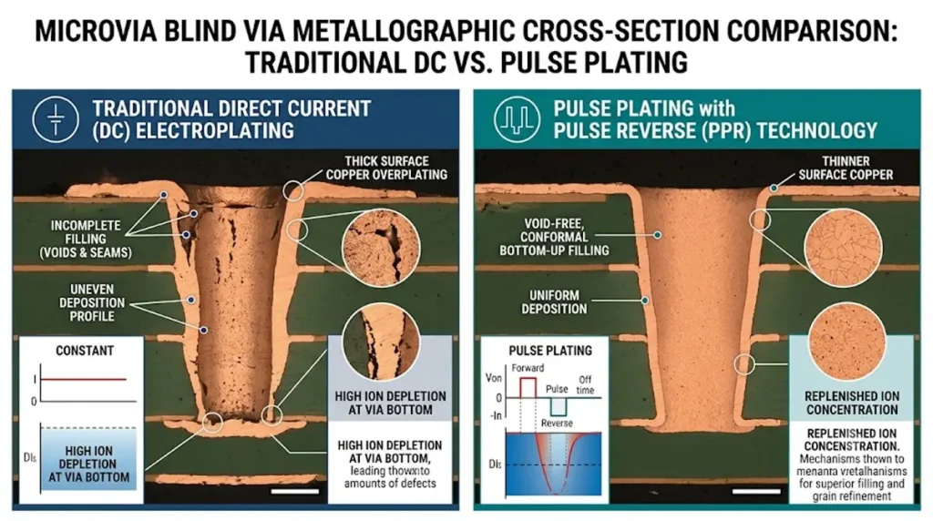
Microvia Blind Via Plating Comparison: DC vs. Pulse Reverse
The Challenge: Traditional Direct Current (DC) electroplating delivers poor throwing power in ultra-small microvias, leaving minute internal voids inside the via holes. These defects are highly prone to fatigue cracking during subsequent environmental thermal cycling tests.
Engineering Solution: Transition completely to a Pulse Copper Electroplating process combined with organic additives specifically optimized for bottom-up via filling. This technique suppresses the interfacial void rate to below 0.5% while ensuring a copper deposit purity of at least 99.9%, providing stable interconnect security for weak signal transmissions in high-sensitivity biosensors.
3. Design Boundaries for Specific Application Scenarios
Ultra-thin rigid-flex technology cannot adopt a “one-size-fits-all” approach. Depending on the end-use ecosystem, reliability requirements, regulatory compliance, and material BOM costs vary significantly:
3.1 Consumer-Grade Health Wearables (e.g., Smartwatches, Fitness Bands)
- Design Priorities: High mechanical flexibility, compact multi-sensor integration, and systematic optimization of the cost structure.
- Material Selection: Adhesiveless polyimide (PI) cores (12.5 μm to 25 μm), rolled-annealed (RA) copper foil (9 μm), and standard Liquid Crystal Polymer (LCP) coverlays.
- Reliability Targets: Conformance to IPC-6013 Class 2 standards. Designed to withstand 200,000 dynamic bending cycles without the risk of conductor trace fracture.
3.2 Medical-Grade Wearables (e.g., Continuous Biometric Monitors, Patch-Type Medical Sensors)
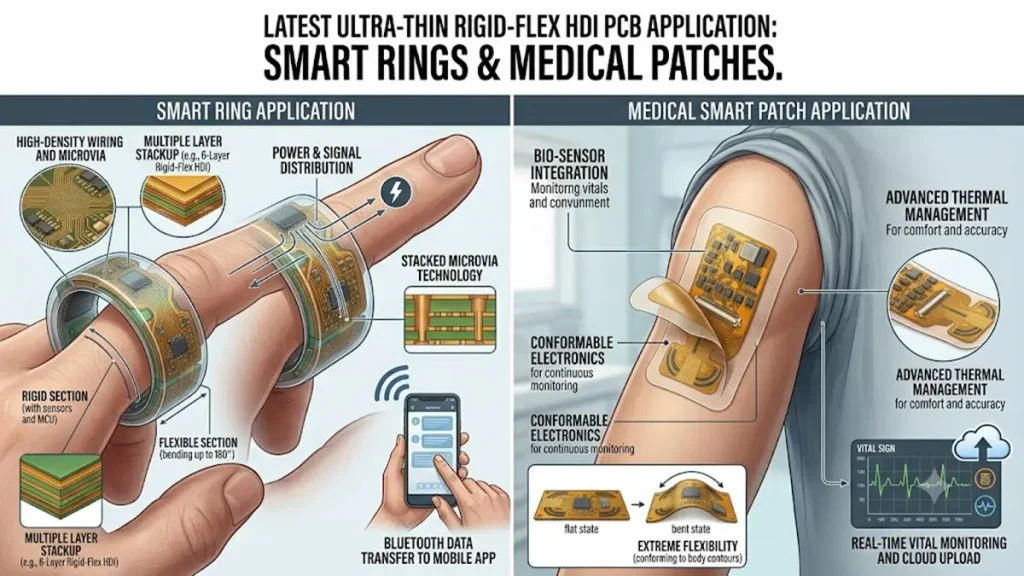
Latest Ultra-Thin Rigid-Flex HDI PCB Application: Smart Rings & Medical Patches
- Design Priorities: Absolute biocompatibility, long-term signal integrity, and stringent regulatory traceability.
- Material Selection: Certified halogen-free and lead-free substrate dielectrics, paired with specialized LCP or biocompatibility-certified coverlays to strictly prevent skin-contact allergies.
- Reliability & Compliance Targets: Must strictly align with the following international regulatory frameworks:
- IPC-6013 Class 3: Implements the highest level of inspection criteria for internal structural integrity, microvia wall thickness, and internal dielectric spacing.
- ISO 13485: Establishes a comprehensive quality management system (QMS) enabling bi-directional traceability from raw material lot numbers to final finished goods.
- ISO 10993: Validated rigorously for continuous skin-contact applications, ensuring assembled devices pass certified testing for non-cytotoxicity and non-irritation.
- IEC 60601-1-2: Executes strict Electromagnetic Compatibility (EMC) testing to prevent external noise from interfering with and contaminating faint analog ECG or blood glucose data streams.
4. Validation and Quality Assurance Protocols
To verify that these advanced stackups meet targeted performance metrics rather than relying solely on nominal capability data, all production panels must pass a rigorous closed-loop verification process in the laboratory:
- Impedance Control Verification: Every production lot must undergo Time-Domain Reflectometry (TDR) testing to guarantee that impedance fluctuations along differential and single-ended signal paths are strictly controlled within a ±5% tolerance window.
- Thermal and Mechanical Stress Screening: Randomly sampled coupons are subjected to Highly Accelerated Life Testing (HALT) and Highly Accelerated Stress Screening (HASS). Continuous continuity monitoring is conducted during extreme temperature cycling from -40°C to +85°C.
- Microsection Structural Analysis: Destructive microsection testing is performed to closely inspect electroplated copper thickness and copper purity within microvias, and to audit for any early signs of internal delamination at the rigid-to-flex transition zones.
Procurement & Technical Sourcing FAQ
What is the proven thickness and layer-count limit for mass production (HVM) versus your laboratory prototyping?
For high-volume manufacturing (HVM), our proven and reliable total thickness baseline is 0.2 mm to 0.3 mm for 2 to 8-layer symmetric stackups. While our laboratory/R&D limit can push line width/spacing down to 10 μm and registration to ±0.005 mm, the established HVM baseline for stable yields is 25 μm for line/space and 60 μm to 75 μm for microvia core diameter. Any via budget ≤ 40 μm is successfully routed within our Advanced Low-Volume / High-End Medical Phase to ensure mass production faces zero yield drops or unexpected cost inflation.
How do you mitigate warpage and SMT yield risks associated with ultra-thin asymmetric rigid-flex designs?
We mitigate warpage by enforcing a strictly symmetrical stackup configuration (e.g., matching the rigid FR-4 and adhesiveless PI layers perfectly across the core). Mechanically, we utilize a specialized low-warpage lamination profile where the cooling rate below the Tg point (170°C+) is strictly capped at ≤ 1.5°C/min. This reduces internal residual stresses and keeps final panel warpage at ≤ 0.5%, guaranteeing flawless automated SMT assembly for ultra-small 01005 (0.4×0.2 mm) components.
What regulatory and biocompatibility certifications do you provide for medical-grade skin-contact wearables?
For medical-grade wearables, we fully comply with the ISO 13485 quality management system, providing bi-directional traceability from raw material lot numbers to final finished goods. Furthermore, we utilize substrate dielectrics and coverlays (such as specialized LCP) that are certified under ISO 10993 for continuous skin contact to guarantee non-cytotoxicity and non-irritation. Our manufacturing protocols also align with IPC-6013 Class 3 for structural reliability and support compliance for IEC 60601-1-2 EMC testing.
How do you prevent internal microvia cracking and voiding during environmental thermal cycling?
To prevent early fatigue cracking, we have transitioned entirely away from traditional Direct Current (DC) electroplating to an advanced Pulse Copper Electroplating process. Combined with organic additives optimized for bottom-up filling, this technique suppresses the internal microvia void rate to below 0.5%. It ensures a copper deposit purity of at least 99.9%, maintaining stable interconnect security for weak biometric signals even under harsh HALT/HASS thermal screening (-40°C to +85°C).
What standard materials are in your BOM to achieve both 200,000+ bending cycles and cost-efficiency?
For an optimal balance of cost and high reliability, our standard recommended Bill of Materials (BOM) utilizes adhesiveless Polyimide (PI) cores (12.5 μm thick) and rolled-annealed (RA) copper foil (9 μm base) paired with 25 µm bondplies and coverlays. Adhesiveless PI eliminates the brittle acrylic adhesive layer, which significantly reduces overall thickness while allowing the flexible region to easily exceed 200,000 dynamic 180° bending cycles (at a 5 mm bend radius) without trace fracture. This standardized stackup avoids expensive custom material lead times while meeting IPC-6013 Class 2/3 requirements.
Conclusion
Developing ultra-thin rigid-flex HDI PCB solutions for health wearables is a systematic engineering discipline that requires deep synchronization among material characteristics, design rules, and manufacturing process windows. Thoroughly understanding the boundaries between advanced R&D prototyping limits and validated mass production baselines allows engineering teams to pursue extreme hardware performance while ensuring high production yields and commercial viability.
Technical Support & Business Inquiries:
For Design for Manufacturability (DFM) reviews, stackup validations, or specific material specification consulting tailored to medical or consumer wearable applications, please contact the Engineering Department of Shenzhen Hongda Circuit Technology Co., Ltd. directly at: sales@pcbkr.com.
Conclusion: Bringing AI-Grade Discipline to Standard PCBs
Navigating the line between cutting-edge innovation and cost-effective mass production shouldn’t be a compromise. At [PCBKR / Hongda Circuit Technology], we bridge this gap by reshaping how everyday hardware is built.
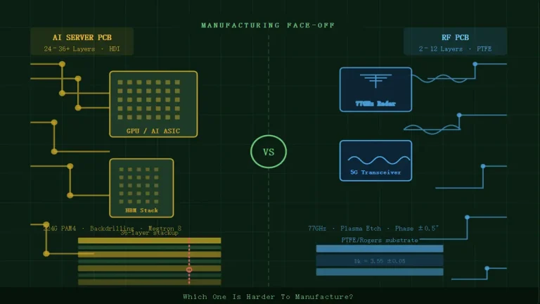
Using top-tier AI server PCB equipment to manufacture traditional PCBs delivers a strategic advantage: interlayer alignment tolerance shrinks from ±75μm to within ±25μm, and differential impedance control tightens to ±5%. Paired with 100% 3D X-Ray inspection, it grants conventional boards chip-level precision, superb signal stability, and near-100% yield.
Our Strategic Partnership to You:
We proudly stand as a strategic partner who possesses the top-tier technical ceiling of the industry’s mega-factories, yet retains the exceptional flexibility and unmatched cost-efficiency required for mid-sized, standard board campaigns. You get zero-defect reliability without paying a premium for tier-1 bureaucracy.
Ready to upgrade your hardware’s reliability?
Submit your Gerber files today for an agile engineering review and a highly competitive quote.
📧 Contact our experts: sales@pcbkr.com
About Author
David Chen https://www.linkedin.com/in/pcbcoming/
David Chen boasts an extensive professional background in PCBA manufacturing, PCBA testing, and PCBA optimization, with specialized expertise in high-precision PCBA fault analysis and rigorous PCBA reliability testing. The author has worked with high-layer-count server PCB fabrication, ultra-low-loss backplane stackups, and thermo-mechanical reliability optimization for AI infrastructure projects involving 112G and 224G PAM4 architectures. Skilled in complex circuit design and cutting-edge advanced PCB manufacturing processes, he delivers solutions that elevate product durability and performance across industrial applications. His technical articles focusing on PCBA manufacturing workflows and testing methodologies are widely cited by industry peers, research institutions, and technical platforms, solidifying his reputation as a recognized technical authority in the global circuit board manufacturing sector.