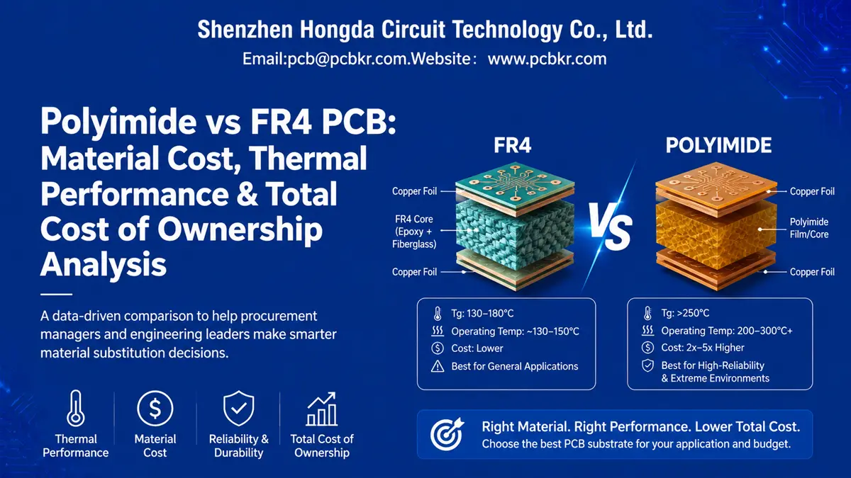
Polyimide vs FR4 PCB: Material Cost, Thermal Performance & Total Cost of Ownership Analysis
When Procurement Teams Face the Polyimide vs FR4 PCB Material Substitution Decision
Most material substitution conversations start the same way. A field failure report lands on your desk. A thermal test reveals delamination at 155°C. Or a customer specification suddenly demands 200,000 flex cycles where your current FR4 design fractures at cycle five. At this stage, you are not looking for a chemistry lecture. You need a binary answer: Does switching from FR4 to polyimide solve the problem, and will the math work in our favor?
This guide is written for that exact moment. We compare polyimide vs FR4 PCB substrate across the four dimensions that actually drive procurement decisions—thermal ceiling, unit cost, mechanical endurance, and signal integrity. We also explain why the material that costs 2× to 5× more upfront can, in specific operational environments, deliver a lower total cost of ownership (TCO) than standard FR4.
At Shenzhen Hongda Circuit Technology Co., Ltd., we process both substrates daily across rigid, flex, and rigid-flex constructions. The data and process notes below reflect what we observe on our fabrication floor, not generic textbook claims.
What FR4 and Polyimide Actually Are (And Why the Comparison Is Never Apples-to-Apples)
Standard FR4: The Baseline PCB Material
FR4 is not a single material. It is a NEMA grade—specifically, a flame-retardant epoxy resin reinforced with woven fiberglass cloth. The “4” simply denotes the performance tier. Within that tier, Tg values range from 130°C on standard grades to roughly 180–210°C on high-Tg variants. For procurement teams, FR4 represents the cost baseline: abundant supply, mature supply chains, and universal PCB fabrication compatibility.
The limitation is thermal. Once operating temperatures approach or exceed the glass transition threshold, FR4 begins to soften. Z-axis expansion accelerates. Plated through-holes experience stress. Over repeated thermal cycles—common in automotive underhood, downhole drilling, or power electronics—this stress propagates into cracks, opens, and intermittent failures.
Polyimide (PI): The High-Performance Alternative
Polyimide is a high-temperature polymer substrate, typically supplied as a film (Kapton® and equivalents) or as a resin system for rigid boards. Its Tg exceeds 250°C, with continuous operating temperatures between 200°C and 300°C. In flexible PCB constructions, polyimide film provides the mechanical backbone that allows dynamic bending without cracking.
The trade-off is cost. Raw polyimide laminate runs 2× to 5× the price of standard FR4. Specialty grades—low-loss variants for RF, or ultra-thin films for micro-flex—can push that multiplier to 8×. Processing is also more demanding: polyimide absorbs roughly 1.5–2.0% moisture by weight (versus ~0.1–0.2% for FR4), which means controlled storage, pre-lamination baking, and tighter process windows during drilling and plating.
Four-Dimension Data-Driven Comparison: Polyimide PCB vs FR4 Cost, Thermal, Mechanical, and Electrical Performance
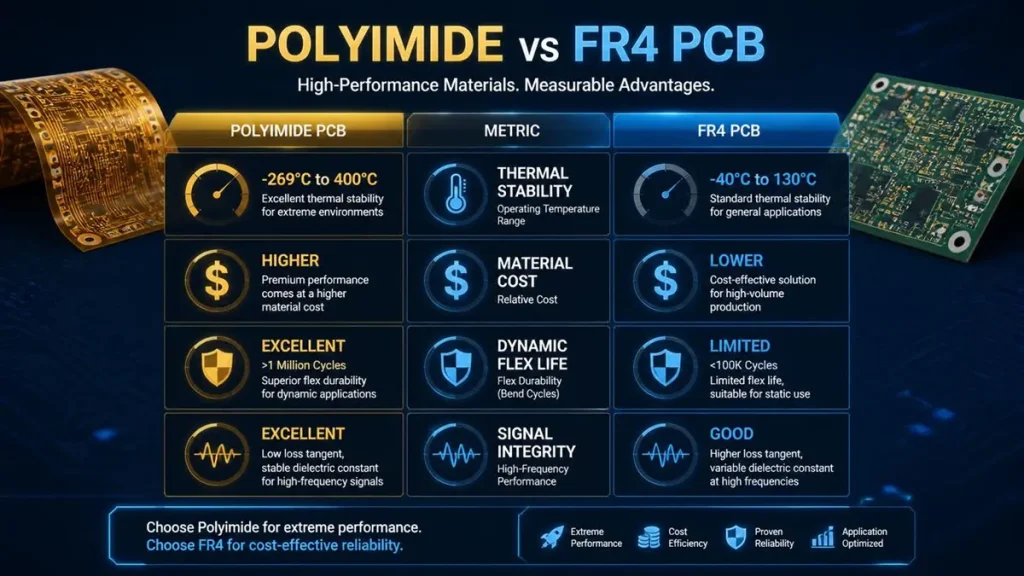
Polyimide vs. FR4 PCB Multi-Dimension Performance Comparison Matrix
The chart below summarizes the divergence between the two materials across the parameters that matter for procurement and engineering sign-off.
Thermal Stability and Glass Transition Temperature (Tg)
For procurement managers evaluating high-Tg PCB material options, the Tg delta is the most decisive number on the datasheet.
| Parameter | Standard FR4 | Polyimide (PI) |
|---|---|---|
| Tg (Glass Transition) | 130–180°C (High-Tg up to 210°C) | >250°C (Typical 260–400°C) |
| Continuous Operating Temp | ~130–150°C | 200–300°C+ |
| Short-Term Peak | ~170°C | 300°C+ |
In practical terms, an FR4 board operating at 140°C is already approaching its mechanical limit. The resin matrix begins to transition from rigid glass to rubbery state. Z-axis CTE spikes from ~50 ppm/°C to over 200 ppm/°C. Plated barrels experience barrel cracking. Over 500 thermal cycles between -40°C and 125°C—a standard automotive qualification profile—standard FR4 shows measurable degradation.
Polyimide, by contrast, maintains dimensional stability well above 200°C. At Hongda, we have fabricated polyimide rigid-flex boards for aerospace clients that must survive 1,000+ cycles between -65°C and 150°C without electrical opens. That is not achievable on FR4, regardless of copper weight or stack-up optimization.
Procurement implication: If your application environment pushes junction temperatures above 130°C, or if thermal cycling is a design requirement, FR4 is not a cost saving. It is a deferred liability.
Material Cost vs. System Total Cost of Ownership (TCO)
This is where most polyimide PCB cost comparison discussions derail. Procurement sees the 2×–5× material premium and stops the conversation. The error is comparing BOM line items instead of system economics.
Consider a medical device PCB operating in a sterilization environment. The board sees repeated autoclave cycles at 134°C. On FR4, the cumulative thermal stress causes pad lifting and via fractures after 18 months in the field. Each field failure triggers a $2,400 service call, parts replacement, and reputational damage with the hospital network. The FR4 board cost $18/unit. The polyimide replacement costs $62/unit. Over a 5-year product life, the FR4 fleet generates 12% annual failure rate; the polyimide fleet generates 0.3%.
The math is not subtle. The “expensive” material is cheaper by a factor of four at the system level.
The crossover point varies by industry, but the pattern is consistent:
- Consumer electronics (stable ambient, no flex): FR4 wins. The system cost delta does not justify the material premium.
- Industrial control (moderate thermal cycling, 5–10 year life): FR4 TCO rises due to maintenance windows. Polyimide becomes competitive.
- Automotive underhood / aerospace / medical implantable: Polyimide TCO is decisively lower. Field failure costs, warranty exposure, and thermal management BOM reductions outweigh the material premium.
At Hongda, our FR4-to-polyimide conversion assessment service models this TCO explicitly. We input your current FR4 stack-up, operating temperature profile, annual volume, and field failure rate. The output is a 24-month TCO projection with break-even volume and risk-adjusted NPV.
Dynamic Flex Life and Mechanical Reliability: Flexible PCB Substrate vs Rigid FR4 Board
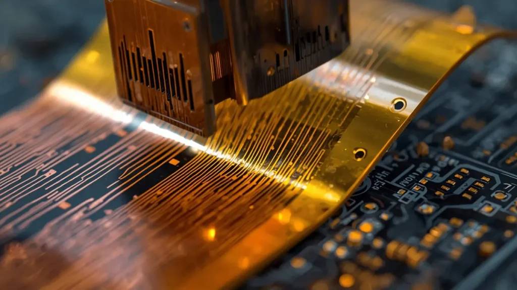
Dynamic Mechanical Bending Test of Flexible Polyimide Substrate
FR4 contains woven fiberglass. It is designed to be rigid. Bend it, and the glass fibers fracture the epoxy matrix. The result is immediate cracking, typically within 1–5 cycles at any meaningful bend radius.
Polyimide film, especially when paired with rolled-annealed (RA) copper rather than electrodeposited (ED) copper, achieves dynamic flex lives measured in hundreds of thousands of cycles. The exact number depends on construction: adhesiveless laminates outperform adhesive-based constructions; thinner copper (1/2 oz or 1/3 oz) extends life; and bend radius (expressed as a multiple of board thickness) is the dominant variable.
Key procurement insight: If your product requires any form of dynamic flex, repeated insertion, or vibration resistance, FR4 is not a viable candidate. The question is not “which material is cheaper?” It is “which material can survive the mechanical specification?” In those cases, polyimide is the only option that passes qualification.
Dielectric Performance: Polyimide vs FR4 Dielectric Constant and Loss Tangent
For RF and high-speed digital designs, the electrical properties of the substrate directly determine signal integrity and transmission loss.
| Parameter | Standard FR4 | Polyimide (PI) |
|---|---|---|
| Dielectric Constant (Dk) | 3.8–4.9 | 2.8–4.1 |
| Dissipation Factor (Df) | 0.004–0.020 | 0.003–0.010 |
Polyimide’s lower Dk (typically 3.2–3.5 for standard grades) means signals propagate faster for a given impedance target. The lower Df (0.002–0.010 depending on grade) reduces dielectric loss at microwave frequencies. For 5G mmWave modules, satellite communication payloads, or high-speed backplanes, this translates to longer trace lengths without repeaters, reduced layer count, and simplified impedance control.
FR4 is serviceable below ~5 GHz. Above that, Df rises and Dk becomes frequency-dependent, causing dispersion and skew. Polyimide does not eliminate these effects, but it pushes the usable frequency ceiling significantly higher—often sufficient to avoid the cost jump to PTFE-based laminates, which can run 10× the price of FR4.
When Polyimide Beats FR4 on Total Cost of Ownership: Four Trigger Scenarios
Procurement teams should flag polyimide as the default recommendation when any of the following conditions are present:
- Ambient or junction temperature exceeds 130°C for sustained periods. FR4’s thermal margin is exhausted. The cost of thermal management (heat sinks, fans, thermal interface materials, enlarged enclosures) often exceeds the polyimide material premium.
- The product requires dynamic flex or tight static bend radii. Wearables, foldable displays, medical catheters, and aerospace harness replacements fall into this category. FR4 is mechanically disqualified.
- Field failure costs exceed $500 per incident. Once warranty, service labor, shipping, and customer downtime are factored, polyimide’s reliability premium pays for itself within the first production year in most industrial and medical applications.
- Signal frequencies exceed 5 GHz or rise times fall below 100 ps. The dielectric loss advantage of polyimide reduces the need for expensive equalization, retimers, or additional signal conditioning layers.
Risk Boundaries: When FR4 Remains the Correct Choice
Polyimide is not universally superior. There are clear boundaries where FR4 is the rational procurement decision:
- Cost-sensitive consumer products with benign thermal environments. A smart home sensor operating at room temperature does not need 250°C Tg. FR4 is the correct economic choice.
- Moisture-sensitive storage constraints. Polyimide’s 1.5–2.0% moisture absorption requires dry storage, pre-assembly baking (typically 120°C for 2–4 hours), and humidity-controlled manufacturing floors. If your supply chain or CM lacks these controls, polyimide introduces yield risk that FR4 does not.
- Design migration overhead. Switching from FR4 to polyimide is not a drop-in replacement. Stack-up redesign, impedance re-calculation, via aspect ratio adjustments, and surface finish re-qualification (ENIG is standard; OSP on polyimide requires process validation) add 3–6 weeks to the NPI cycle. For programs with aggressive launch timelines, this migration cost must be budgeted.
At Hongda, we run both material systems on the same production floor. Our engineers can evaluate whether your current FR4 design is a straightforward polyimide port or requires structural redesign. We do not recommend polyimide when FR4 is the technically and economically correct answer.
FR4-to-Polyimide Conversion Assessment: Hongda’s Advanced PCB Fabrication Technology and Evaluation Service
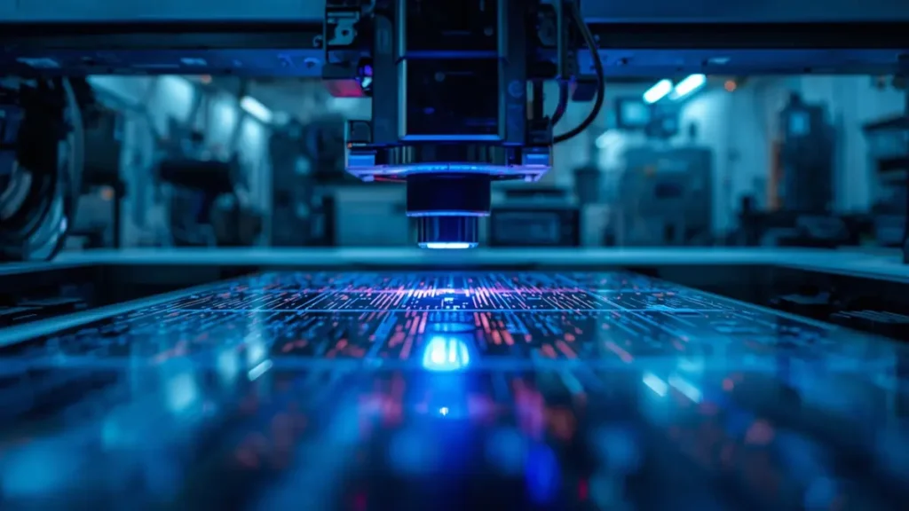
High-Precision LDI Laser Exposure Process for Multilayer Polyimide Circuits
Shenzhen Hongda Circuit Technology Co., Ltd. operates a full-capability PCB fabrication facility supporting both high-volume FR4 production and precision polyimide processing for aerospace, medical, and automotive Tier-1 clients. Our equipment portfolio includes:
- Precision lamination presses with vacuum-assisted bonding and programmable temperature/pressure profiles, critical for polyimide’s narrower process window.
- Laser direct imaging (LDI) for fine-pitch registration on flexible and rigid-flex substrates, maintaining ±8 µm layer-to-layer alignment on 8+ layer polyimide builds.
- Controlled-depth drilling and back-drilling for high-speed polyimide designs requiring stub reduction.
- Automated optical inspection (AOI) and flying probe testing configured for both rigid and flex circuit geometries.
- Impedance control to ±5% on polyimide substrates, validated through TDR measurement and S-parameter extraction up to 40 GHz.
What Our FR4-to-Polyimide Conversion Assessment Includes
If you are currently shipping an FR4 design and suspect polyimide may reduce your TCO, our engineering team provides a structured evaluation:
- Thermal and mechanical risk audit: We model your operating temperature profile, thermal cycle count, and vibration spectrum against FR4’s rated limits. The output is a quantitative failure probability curve.
- Stack-up portability analysis: We assess whether your current layer count, copper weights, and via structures translate directly to polyimide, or whether redesign is required.
- TCO impact modeling: We calculate the 24-month total cost delta, factoring in material premium, reduced thermal management BOM, warranty savings, and yield adjustments.
- DFM and lead-time forecast: Polyimide fabrication requires longer lamination cycles and tighter environmental controls. We provide realistic lead-time and MOQ projections based on your annual volume.
Request a FR4-to-Polyimide Conversion Assessment → Email: pcb@pcbkr.com
Polyimide vs FR4 PCB: Multi-Dimension Performance Overview
The radar chart below visualizes the relative strengths and weaknesses of each material across the six dimensions that drive procurement and engineering decisions.
Frequently Asked Questions: PCB Material Selection Guide for Procurement Teams
What is the realistic price difference between polyimide and FR4 PCB boards in 2025–2026?
For standard 2-layer constructions, polyimide laminate runs 2× to 3× the cost of FR4. For multilayer rigid-flex or high-frequency grades, the multiplier extends to 5×–8×. However, the relevant metric is not material cost—it is system TCO. In automotive, aerospace, and medical applications, the field failure cost avoided by polyimide typically recovers the material premium within 12–18 months.
Can I use polyimide for a rigid PCB, or is it only for flexible circuits?
Polyimide is used in both. Rigid polyimide boards (sometimes called “all-polyimide” or “thermally stable epoxy-polyimide hybrids”) are common in aerospace and defense where Tg >250°C is mandatory. Flexible circuits use polyimide film (typically 25 µm or 50 µm) as the dielectric. Rigid-flex combines both: rigid FR4 or polyimide sections for component mounting, with polyimide flex layers for interconnection.
How do I know if my current FR4 design is thermally stressed enough to justify polyimide?
Three signals indicate thermal stress beyond FR4’s safe margin: (a) operating temperature within 20°C of the material’s Tg for more than 20% of duty cycle; (b) thermal cycling exceeding 500 cycles between -40°C and 125°C over product life; (c) any field failure mode involving barrel cracks, pad lifting, or delamination. If any apply, polyimide should be evaluated.
Does polyimide improve signal integrity for high-speed digital designs compared to FR4?
Yes, but with caveats. Polyimide’s lower Dk (3.2–3.5 vs. 4.2–4.8 for FR4) and lower Df (0.003–0.010 vs. 0.015–0.025) reduce dielectric loss and improve impedance consistency. For designs above 5 GHz or with rise times below 100 ps, this translates to measurable insertion loss improvement. However, polyimide is not a substitute for proper stack-up design, controlled impedance routing, and via optimization. It is one component of a signal integrity strategy.
What lead-time and MOQ penalties should I expect when switching from FR4 to polyimide?
Polyimide lamination requires longer cure cycles and tighter environmental controls, adding 2–3 days to fabrication lead time. MOQs are typically higher for specialty polyimide laminates because suppliers require minimum roll quantities. At Hongda, we mitigate this by maintaining strategic inventory of standard polyimide films (Kapton® EN, HN, and low-loss variants), which allows us to support prototype volumes (as low as 5 pieces for rigid-flex) without imposing full-roll MOQs on the customer.
Final Recommendation: A Decision Framework for PCB Material Replacement and Cost-Down Strategy
The polyimide vs FR4 PCB material decision is not a religious debate. It is a boundary condition problem.
- If your product operates below 100°C, has no flex requirement, and signal frequencies stay below 3 GHz: FR4 is the correct, defensible choice. Do not over-engineer.
- If your product operates above 130°C, requires dynamic flex, or failure costs exceed $500 per incident: Polyimide is not a luxury. It is risk mitigation with a quantifiable ROI.
- If you are in the ambiguous zone (100–130°C, moderate thermal cycling, cost-sensitive): Run the TCO model. At Hongda, we provide this analysis at no charge for qualified programs. The output is a number, not a sales pitch.
Material substitution is a procurement lever, but only when the analysis includes the full cost stack—not just the laminate line item. That is the difference between a cost-down initiative that works on paper and one that survives contact with reality.
Ready to evaluate polyimide for your next program?Submit your current FR4 design for a polyimide conversion assessment and receive a thermal risk audit, stack-up portability report, and 24-month TCO model within 48 hours.
Shenzhen Hongda Circuit Technology Co., Ltd. | www.pcbkr.com
Advanced PCB fabrication services: rigid, flex, rigid-flex, HDI, and high-frequency substrates.
ISO 9001 certified | IPC-A-600 compliant | Supporting aerospace, medical, automotive, and industrial clients globally.
About Author
David Chen https://www.linkedin.com/in/pcbcoming
David Chen boasts an extensive professional background in PCBA manufacturing, PCBA testing, and PCBA optimization, with specialized expertise in high-precision PCBA fault analysis and rigorous PCBA reliability testing. The author has worked with high-layer-count server PCB fabrication, ultra-low-loss backplane stackups, and thermo-mechanical reliability optimization for AI infrastructure projects involving 112G and 224G PAM4 architectures. Skilled in complex circuit design and cutting-edge advanced PCB manufacturing processes, he delivers solutions that elevate product durability and performance across industrial applications. His technical articles focusing on PCBA manufacturing workflows and testing methodologies are widely cited by industry peers, research institutions, and technical platforms, solidifying his reputation as a recognized technical authority in the global circuit board manufacturing sector.