Ceramic PCB vs FR4 vs MCPCB: Cost, Performance & Complete Material Selection Guide
Ceramic PCB vs FR4 – The Core Substrate Decision That Defines Your Hardware Performance
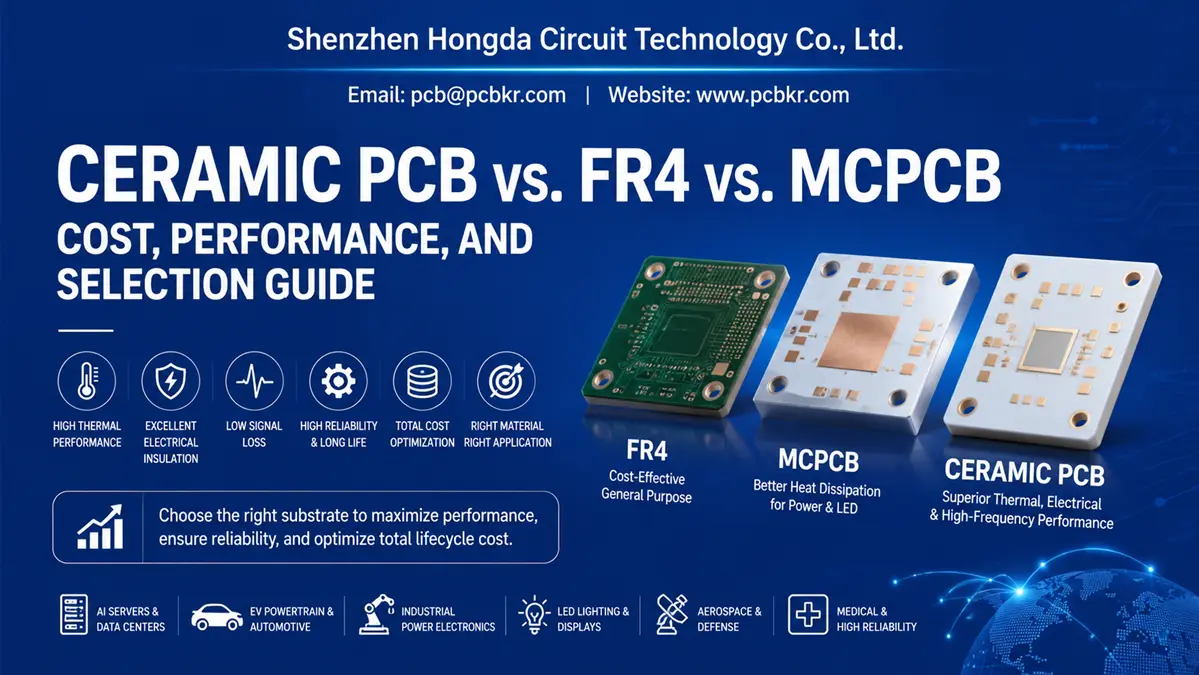
Your PCB substrate material sets the hard limits for power handling, heat dissipation, signal stability and long-term product reliability. When weighing Ceramic PCB vs FR4, you also need to factor in MCPCB as the middle-ground thermal alternative, as each material delivers vastly different thermal, electrical and cost outcomes:
- FR4: Low-cost baseline for low-power consumer electronics
- MCPCB (Metal Core PCB): Mid-tier thermal solution for LED lighting and medium-power supplies
- Ceramic PCB (Alumina Al₂O₃ / Aluminum Nitride AlN): Top-tier thermal & high-frequency substrate, thermal conductivity up to 230 W/m·K
Shenzhen Hongda Circuit Technology Co., Ltd. specializes in DPC, DBC, AMB ceramic substrate manufacturing with vacuum sputtering, laser machining and precision lithography lines. Our ceramic circuit boards eliminate thermal breakdown risks for AI servers, EV power inverters and aerospace electronic systems.
Why PCB Substrate Material Determines Cost & Long-Term Reliability
Substrate choice is the core design factor controlling heat spreading, dielectric stability and total product lifecycle cost.
Standard glass epoxy FR4 sheets are cheap for simple circuit routing, yet their poor thermal conductivity creates severe local heat buildup when used in modern high-power hardware. This thermal bottleneck forces hardware engineers and procurement teams to balance low upfront material cost against recurring expenses from field failures and extra cooling components.
Many procurement teams only focus on initial board pricing, while hardware engineers prioritize signal integrity and thermal headroom under peak loads.
- Over-specifying ceramic substrates for low-power consumer goods adds unnecessary material costs
- Under-specifying high-power hardware with regular FR4 leads to thermal degradation, cracked solder joints and early device failure
Balanced design requires matching your device’s actual operating thermal stress to substrate performance parameters.
Core Structural Differences: FR4, MCPCB & Ceramic PCB
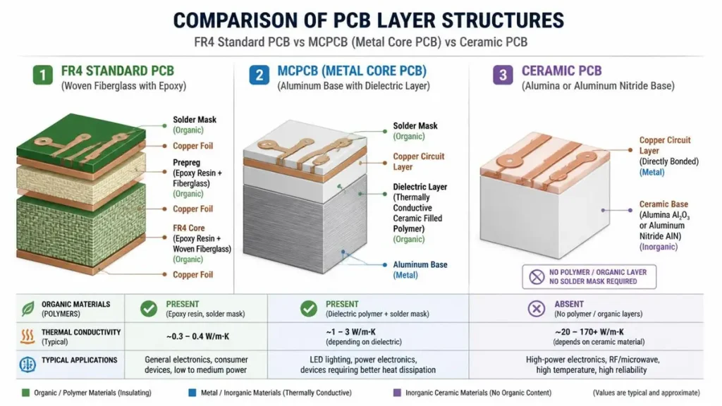
Comparison of PCB Layer Structures: FR4 vs. MCPCB vs. Ceramic PCB
1. FR4 Standard PCB
FR4 uses woven fiberglass saturated with flame-retardant epoxy resin. It is a mature, low-cost universal material for low-frequency, low-power electronics.
Its all-polymer base acts as a natural thermal barrier, blocking vertical heat transfer from hot chips to external heat sinks.
2. MCPCB (Metal Core PCB)
MCPCB replaces thick FR4 core with an aluminum or copper metal base, bonded to a thin thermally conductive insulating dielectric layer.
It delivers better horizontal heat spreading for high-brightness LED panels and basic power supplies. However, the organic dielectric layer creates a permanent thermal resistance bottleneck, limiting vertical heat dissipation efficiency.
3. Ceramic PCB
Ceramic substrates contain zero organic binders, made of dense crystalline inorganic materials: alumina (Al₂O₃) or aluminum nitride (AlN). Copper traces are directly bonded or sputtered onto bare ceramic without polymer intermediate layers.
This construction delivers outstanding vertical thermal conductivity, zero risk of high-temperature delamination, and superior electrical insulation under extreme operating environments.
Side-by-Side Performance Comparison
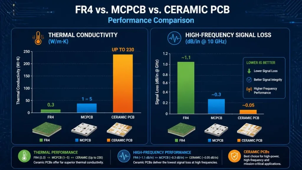
Performance Comparison: FR4 vs. MCPCB vs. Ceramic PCB (Thermal Conductivity & Signal Loss)
Lab testing proves ceramic PCBs deliver up to 800x higher thermal conductivity and far lower high-frequency signal loss than FR4 and metal core boards.
| Performance Parameter | FR4 Laminate PCB | MCPCB (Metal Core) | Ceramic Substrate PCB |
|---|---|---|---|
| Thermal Conductivity | ~0.3 W/m·K | 1–8 W/m·K (high-grade version) | 20–230 W/m·K (Al₂O₃:20–30; AlN:170–230) |
| High-Frequency Signal Loss | High signal attenuation | Moderate loss performance | Ultra-low insertion loss |
| CTE Match to Silicon Die | Poor mismatch (14–17 ppm/°C) | Moderate mismatch (~22 ppm/°C) | Near-perfect match (~4.5 ppm/°C) |
| Continuous Temperature Resistance | Below 130°C; high-Tg max 180°C | Medium temperature threshold | Excellent stability >300°C |
| Raw Board Cost | Lowest baseline price | Mid-range cost | High premium cost |
Key Performance Breakdown
- Thermal Conductivity FR4 barely transfers heat, only suitable for low power density devices. Advanced aluminum MCPCB improves horizontal heat spreading but is blocked by organic dielectric. Alumina ceramic enables fast vertical heat extraction, while premium AlN substrates handle extreme high heat flux for power semiconductors.
- High-Frequency Electrical Performance Ceramic substrates maintain stable dielectric constant and ultra-low loss tangent across wide temperature and frequency ranges, ideal for mmWave radio circuits. FR4 suffers heavy signal attenuation and dielectric drift at GHz frequencies.
- Thermal Expansion (CTE) & Mechanical Reliability Ceramic’s CTE closely matches silicon chips. During repeated thermal cycling, thermal stress on solder joints and die attach layers is minimized, preventing cracking. FR4 and aluminum MCPCB have large CTE mismatches, causing joint fatigue over long operation cycles.
- Temperature Resistance Ceramic substrates withstand sustained temperatures over 300°C without delamination or deformation, while FR4’s epoxy resin softens rapidly above 130°C.
Manufacturing Cost Breakdown & Total Cost of Ownership (TCO)
Ceramic PCBs carry higher upfront costs due to expensive raw ceramic blanks and complex metallization processes:
- Ceramic sheets require precision high-temperature sintering and brittle-material processing
- Copper bonding technologies (DPC vacuum sputtering, DBC high-temperature furnace bonding, AMB active metal brazing) demand specialized production equipment
- FR4 manufacturing uses mass-scalable fiberglass and epoxy with simple print-and-etch workflows
However, focusing only on initial PCB price ignores full-system total cost of ownership:
If you use FR4 or low-end MCPCB beyond their thermal limits, you will face:
- Mass product field failures & warranty compensation
- Extra bulky heat sinks, thermal paste and forced cooling systems
- Production downtime from defective units
For high-power, long-lifecycle equipment, ceramic substrates reduce overall system costs by eliminating cooling hardware overhead and cutting failure rates.
When to Choose FR4 or MCPCB Instead of Ceramic
Pick FR4 if:
- Your product targets cost-sensitive consumer electronics
- Low power density, low heat generation
- Operating frequency below 10 GHz Examples: household remote controls, general appliance control boards, basic low-speed digital circuits
Pick MCPCB if:
- Moderate heat generation, heat needs to spread horizontally over a large area
- Mid-power LED lighting modules, medium-power power supplies Budget cannot support ceramic substrates, and vertical heat flux is not extreme
When High-Performance Ceramic PCB Is Worth the Extra Investment
Ceramic substrates become mandatory when either condition applies:
- Heat density exceeds 10 W/cm²
- Operating frequency exceeds 10 GHz
Typical Application Scenarios for Ceramic PCB
- High-power IGBT power modules, EV traction inverters
- AI computing accelerators, high-density laser diode packages
- Satellite communication RF circuits, aerospace radar systems
- Equipment with strict size limits (no space for large heat sinks)
- Devices under extreme thermal cycling, heavy vibration or harsh environments
AlN ceramic is the top choice for silicon die direct attachment, as its matched CTE eliminates thermal cycling solder crack risks. Alumina ceramic offers balanced thermal performance at a lower premium for mid-tier power modules and automotive sensors.
Hidden Cost & Engineering Pitfalls Sourcing Managers Must Avoid
- Short-sighted substrate selection Choosing cheap FR4 to cut initial board cost often leads to expensive mass returns later, caused by CTE mismatch cracking solder joints. Adding extra heat sinks and cooling fans erases all upfront PCB cost savings.
- Specialized assembly requirements for ceramic substrates Direct die bonding on ceramic needs precise metallization coatings (AuSn eutectic plating, silver sintering). Poor metallization will reduce assembly yield dramatically.
- Uncertified third-party subcontractors Outsourced ceramic processing creates risks including copper layer delamination, weak copper adhesion and invisible microcracks on ceramic cores. Always source from factories with full in-house ceramic production lines.
How to Vet Reliable Ceramic PCB Manufacturers in China
Qualified ceramic circuit suppliers must own all core production workflows in-house, without outsourcing critical processes:
- Vacuum sputtering & DPC fine-line lithography
- High-temperature DBC / AMB bonding furnaces
- Precision laser drilling & ceramic cutting Full in-house quality inspection systems are mandatory: AOI automated optical inspection, X-ray void testing for bonded copper layers, cross-section microscope analysis, laser via inspection and thermal shock cycling validation.
Shenzhen Hongda Circuit Technology Co., Ltd. In-House Capabilities
We operate integrated full-process ceramic substrate production lines:
- Precision vacuum sputtering & automated electroplating for ultra-fine DPC circuits
- High-temperature bonding furnaces for heavy-copper DBC and AMB substrates
- Complete internal quality control: X-ray bonding integrity test, thermal shock validation, laser via defect diagnosis
Our engineering team provides DFM reviews, rapid prototype manufacturing and mass production for alumina and AlN ceramic boards. Contact our sales team via sales@pcbkr.com for technical support and quotations.
Step-by-Step Substrate Selection Decision Framework
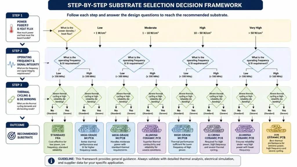
Step-by-Step Substrate Selection Decision Framework: FR4 vs. MCPCB vs. Ceramic PCB
Use this structured workflow to avoid over-engineering or under-specifying your PCB substrate:
- Calculate power density & heat flux
- Heat flux < 2 W/cm²: Standard FR4 is most cost-effective
- Heat flux 2–10 W/cm² with horizontal heat spreading demand: High-grade aluminum MCPCB
- Heat density > 10 W/cm²: Ceramic substrate required
- Evaluate operating frequency & signal integrity demands
- Frequency < 10 GHz: FR4 or high-speed organic laminates work fine
- Frequency > 10 GHz with stable impedance requirements: Alumina or AlN ceramic PCB
- Check thermal cycling & silicon die bonding conditions If your design uses large bare silicon dies and undergoes fast temperature swings, select AlN ceramic to match silicon CTE and prevent joint failure.
- Compare upfront board cost vs full system lifecycle cost If FR4 requires heavy, costly external cooling hardware, switching to ceramic often simplifies mechanical design and lowers total system cost.
Final Conclusion: Build a Data-Driven Substrate Selection Strategy
Choosing between FR4, MCPCB and ceramic PCBs is a tradeoff between immediate component cost and long-term equipment reliability.
Cutting PCB material costs by using FR4 in high-power applications always results in system overheating, field failures and costly after-sales losses. Matching your thermal, frequency and mechanical requirements to substrate performance data lets engineering and procurement teams balance performance and budget.
As AI computing, electric vehicles and aerospace high-frequency electronics develop rapidly, ceramic substrates are evolving from niche specialty materials into mainstream high-power circuit solutions.
Shenzhen Hongda Circuit Technology Co., Ltd. supports hardware developers with professional DFM design reviews, fast-turn prototypes and volume manufacturing for alumina and aluminum nitride ceramic boards, maximizing device reliability and thermal efficiency for next-generation electronics.
FAQ for Global Electronic Procurement Teams
How to fully assess a Chinese ceramic PCB factory before placing orders?
Request full process proof that all core manufacturing steps (DPC sputtering, DBC/AMB furnace bonding, laser via drilling, precision etching) are completed in-house instead of outsourced. Ask for test reports including AOI inspection data, X-ray bonding layer void analysis and thermal cycling test records. Start cooperation with small prototype batches to verify quality before mass production.
What is the core difference between alumina (Al₂O₃) and AlN ceramic manufacturers?
The gap lies in thermal conductivity and target applications.
Alumina (Al₂O₃, 20–30 W/m·K): Cost-effective for automotive sensors, mid-power LED modules and cost-controlled power assemblies
Aluminum Nitride (AlN, 170–230 W/m·K): For extreme high heat flux scenarios including high-power IGBT modules, laser packages and AI accelerators, where silicon-matched CTE is critical.
Can Chinese ceramic PCB manufacturers support low-volume prototype development and online instant quotes?
Yes. Professional manufacturers like Shenzhen Hongda Circuit Technology Co., Ltd. provide flexible small-batch prototyping plus dedicated engineering review services. Design teams can validate thermal and electrical performance on physical prototypes before committing to mass production tooling.
What mandatory certifications and internal testing must a professional ceramic PCB supplier hold?
At minimum, ISO 9001 quality management certification. Beyond standard certification, the factory must run full internal test workflows for ceramic-specific defects:
X-ray inspection to detect voids inside DBC/AMB copper bonding layers
Cross-section microscopic analysis for DPC copper adhesion strength
Laser microscope via integrity testing
Regular thermal shock cycle testing to guarantee delamination resistance
Why are ceramic PCBs more expensive than standard laminates, and how to control ceramic substrate costs?
Higher costs stem from expensive ceramic raw blanks, high-temperature sintering/bonding equipment, laser processing and ultra-tight production tolerances. Cost control tips:
Select alumina ceramic when its thermal performance fully meets your requirements; reserve high-performance AlN only for ultra-high heat zones
Invite your supplier for early-stage DFM optimization to optimize panel layout and reduce complex processing steps before tooling launch
About Author
David Chen https://www.linkedin.com/in/pcbcoming
David Chen boasts an extensive professional background in PCBA manufacturing, PCBA testing, and PCBA optimization, with specialized expertise in high-precision PCBA fault analysis and rigorous PCBA reliability testing. The author has worked with high-layer-count server PCB fabrication, ultra-low-loss backplane stackups, and thermo-mechanical reliability optimization for AI infrastructure projects involving 112G and 224G PAM4 architectures. Skilled in complex circuit design and cutting-edge advanced PCB manufacturing processes, he delivers solutions that elevate product durability and performance across industrial applications. His technical articles focusing on PCBA manufacturing workflows and testing methodologies are widely cited by industry peers, research institutions, and technical platforms, solidifying his reputation as a recognized technical authority in the global circuit board manufacturing sector.