Gimbal Controller PCB: Design, Manufacturing, and Assembly for OEM Applications
A gimbal controller PCB integrates motion sensing, real-time processing, motor control, and power management to stabilize cameras and other payloads. For OEM buyers, successful manufacturing depends on more than bare-board fabrication: IMU placement, motor-drive noise, thermal performance, assembly quality, and functional testing must be addressed together. Shenzhen Hongda Circuit Technology Co., Ltd. supports PCB manufacturing and PCBA assembly requirements for custom electronic products, subject to project specifications and confirmed capabilities.
Looking for a Gimbal Controller PCB manufacturer? This guide explains how to select the right PCB architecture, control electrical noise, specify manufacturing requirements, evaluate assembly quality, and prepare an accurate RFQ for prototype or production orders.
Table of Contents
- What Does a Gimbal Controller PCB Do?
- Which PCB Architecture Is Best for a Gimbal Controller?
- How Should You Design the IMU Layout to Reduce Noise?
- How Do You Design Power and Motor-Drive Circuits?
- Which PCB Materials, Copper Weights, and Layer Stacks Should You Specify?
- What Manufacturing Problems Can Affect Reliability?
- Which PCB Assembly and Inspection Processes Are Required?
- How Do You Qualify a Gimbal Controller PCB Manufacturer?
- How Much Does a Custom Gimbal Controller PCB Cost?
- How Can You Request a Gimbal Controller PCB Prototype or Production Quote?
- Frequently Asked Questions
What Does a Gimbal Controller PCB Do?
A gimbal controller PCB processes motion-sensor data and controls motors to maintain a desired camera or payload orientation. Its design typically combines a microcontroller, inertial measurement unit (IMU), motor-control circuitry, power-management components, communication interfaces, and supporting passive components.
Unlike a general-purpose control board, a gimbal controller PCB must account for interactions between motion sensing, motor switching, mechanical vibration, and real-time control.
How Does a Gimbal Controller PCB Work?
A typical control system follows this sequence:
- The IMU measures angular velocity and acceleration.
- The microcontroller processes sensor data and estimates orientation.
- The control algorithm calculates the required correction.
- The motor driver regulates the motor current or generates the required drive signals.
- Feedback from the sensor helps the system adjust its response continuously.
The PCB must support reliable signal acquisition, predictable power delivery, and suitable communication between these functional blocks.
Which Applications Require Custom Gimbal Controller PCBs?
Custom gimbal controller PCBs are used in applications where stabilization performance, compact dimensions, interface compatibility, or environmental requirements make a generic controller unsuitable.
Typical applications include:
- Drone camera gimbals: Stabilization for aerial photography, inspection, mapping, and surveying.
- Handheld camera stabilizers: Compact electronics for portable imaging equipment.
- Industrial inspection systems: Stabilized cameras used for machine vision, infrastructure inspection, and remote monitoring.
- Robotic vision platforms: Camera positioning and stabilization for mobile robots and automated inspection equipment.
- Professional imaging equipment: Electronic control for cinema cameras and specialized optical payloads.
For OEM buyers, application requirements should be defined before selecting the PCB stackup, component packages, connectors, and assembly process.
Which PCB Architecture Is Best for a Gimbal Controller?
The best architecture depends on the number of controlled axes, motor current, IMU requirements, available space, thermal constraints, and system integration strategy. A two-layer board may be sufficient for a relatively simple design, while a four-layer board can provide more routing flexibility and a better opportunity to establish continuous reference planes.
| PCB architecture | Potential advantages | Main considerations |
|---|---|---|
| Two-layer integrated PCB | Lower layer count and potentially lower fabrication cost | Routing congestion, return paths, and noise management |
| Four-layer integrated PCB | More routing flexibility and dedicated reference-plane options | Stackup cost and layer-planning requirements |
| Separate IMU and controller boards | Flexible sensor positioning and mechanical integration | Interconnect reliability, cabling, and assembly complexity |
| Separate controller and motor-driver boards | Greater separation of control and power electronics | Additional connectors, wiring, and system integration effort |
Should You Use a Two-Layer or Four-Layer Gimbal Controller PCB?
A two-layer PCB can work when the circuit is relatively simple, routing density is manageable, and sensitive signals can be separated adequately from switching-current paths.
A four-layer PCB may be preferable when the design requires dense MCU routing, multiple power rails, communication interfaces, or more controlled return paths. However, additional layers do not automatically guarantee lower noise or better stabilization.
The final decision should follow schematic review, placement analysis, routing constraints, and electrical validation.
Should the IMU and Motor Drivers Share One PCB?
An integrated PCB can reduce the number of interconnects and simplify assembly. However, motor-driver switching currents and power-conversion circuits can complicate the design of sensitive sensor circuitry.
A separate IMU board may provide greater freedom to position the sensor relative to the mechanical rotation axes. This approach also introduces additional connectors, wiring, and mechanical tolerances.
Before choosing an architecture, OEM engineering teams should evaluate:
- Required sensor position and orientation.
- Motor current and switching characteristics.
- Available PCB area and enclosure geometry.
- Cable length and connector reliability.
- Assembly cost and serviceability.
- Mechanical vibration and resonance behavior.
Shenzhen Hongda Circuit Technology Co., Ltd. can evaluate PCB fabrication and assembly requirements based on the supplied design files and confirmed manufacturing scope.
How Should You Design the IMU Layout to Reduce Noise?
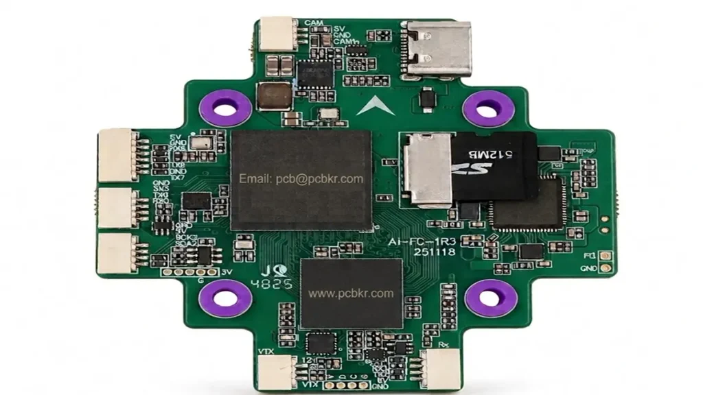
Gimbal Controller PCB Layout and SMT Assembly Details
A reliable IMU layout requires careful placement, appropriate power decoupling, controlled return paths, and separation from noisy switching circuits. These measures help reduce electrical interference, but they cannot independently eliminate mechanical vibration, sensor bias, or control-algorithm problems.
Where Should the Gyroscope and Accelerometer Be Placed?
The IMU should be positioned according to the sensor manufacturer’s recommendations and the mechanical reference frame of the gimbal.
Key considerations include:
- Maintaining the intended sensor orientation.
- Avoiding unnecessary distance between the sensor and its local decoupling capacitors.
- Following the component manufacturer’s exposed-pad and mounting requirements, where applicable.
- Avoiding mechanically unstable PCB regions when sensor accuracy depends on the local vibration environment.
- Keeping the sensor away from avoidable sources of heat and strong electrical interference.
The sensor position should also be coordinated with the enclosure, mounting points, and mechanical rotation axes. A PCB layout that appears electrically acceptable may still perform poorly if the sensor experiences unsuitable mechanical motion.
How Should Ground Planes and Return Paths Be Designed?
A continuous reference plane can provide predictable return paths and help reduce loop area. Unnecessary splits, gaps, and routing detours beneath sensitive signals should be avoided.
For motor-control circuits, the layout engineer should identify high-current switching loops and minimize their area. The sensor interface and low-level analog circuitry should not share poorly controlled return paths with high-current switching loops.
Grounding must be designed around the actual circuit topology. Arbitrarily splitting ground planes can create additional return-path problems rather than solve them.
How Can Switching Regulators and Motor Drivers Affect IMU Signals?
Switching regulators and motor drivers generate current transients and voltage changes that can couple into sensitive circuits through power rails, ground impedance, electric or magnetic fields, and parasitic capacitance.
Recommended design practices include:
- Placing input and output decoupling components according to the regulator data sheet.
- Minimizing high-current switching-loop area.
- Routing sensitive sensor signals away from noisy switching nodes.
- Reviewing the placement of inductors, MOSFETs, and high-current connectors.
- Verifying sensor power quality under representative operating conditions.
Where performance is critical, engineers should compare sensor data with the motor drivers disabled and enabled. Measurements should use a repeatable test setup and representative operating loads.
How Should Sensor Power Supplies Be Designed?
The power architecture should meet the IMU’s specified voltage, noise, startup, and transient requirements.
A dedicated low-noise regulator may be appropriate for some designs, but its necessity depends on the sensor, upstream power supply, current demand, and noise budget. The regulator’s stability, dropout voltage, power dissipation, and required capacitors must also be evaluated.
Manufacturing implication: DFM review should identify component-placement restrictions, fine-pitch routing constraints, and assembly access issues before fabrication. Electrical noise performance must then be validated at the assembled-board or system level.
How Do You Design Power and Motor-Drive Circuits for a Gimbal Controller PCB?
Power and motor-drive design must account for input voltage, operating current, switching behavior, thermal limits, protection requirements, and the sensitivity of the control circuitry. These requirements should be defined before PCB fabrication and PCBA assembly begin.
How Do You Select the MCU and Motor Driver?
The MCU should support the required control-loop timing, sensor interfaces, communication protocols, memory, and firmware architecture.
The motor driver must match the motor type, voltage range, current requirements, control method, and thermal constraints.
During component selection, OEM engineering teams should verify:
- Operating and absolute-maximum ratings.
- PWM and feedback-interface requirements.
- Current-sensing requirements.
- Package dimensions and thermal-pad design.
- Component availability and lifecycle status.
- Firmware compatibility and calibration requirements.
A component should not be selected solely because it fits the PCB footprint. Its electrical behavior and thermal performance must also match the application.
How Should Power Rails Be Organized?
A typical design may include separate power rails for the main controller, IMU, communication interfaces, and motor-drive stage.
The appropriate arrangement depends on the selected components and the power budget. Some circuits can share a supply with suitable filtering and layout, while others may benefit from separate regulation.
The design should account for:
- Input-voltage variation.
- Startup and shutdown behavior.
- Motor acceleration and deceleration.
- Transient current demand.
- Reverse-polarity and overcurrent protection, where required.
- Ground-return paths and regulator stability.
The power tree should be documented in the design package so that the PCB manufacturer and assembly team can understand component placement, thermal requirements, and test access.
How Do You Manage Current Capacity and Thermal Hotspots?
Copper thickness alone does not determine the safe current capacity of a PCB. Trace geometry, copper distribution, board construction, ambient temperature, airflow, and acceptable temperature rise all affect thermal performance.
For high-current motor-drive circuits, engineers should review copper width, plane area, vias, connector ratings, MOSFET losses, and heat transfer into the surrounding structure.
Thermal analysis should be followed by testing under representative loads when the application warrants it.
For designs with demanding current requirements, see the High Current PCB manufacturing guide for related manufacturing considerations.
Which PCB Materials, Copper Weights, and Layer Stacks Should You Specify?
Most conventional gimbal controller PCBs can be evaluated using FR-4, but the final material and construction must match electrical, mechanical, thermal, and environmental requirements. Specialized materials should be selected only when the design justifies their cost or performance advantages.
Is FR-4 Suitable for a Gimbal Controller PCB?
FR-4 is a common starting point for digital control electronics, sensor interfaces, and many motor-control applications.
Material selection should consider operating temperature, dielectric properties, mechanical requirements, fabrication compatibility, and the intended product lifecycle.
A material change may affect cost, lead time, and assembly processing. The required material grade should therefore be specified in the manufacturing documentation rather than left to an unapproved substitution.
How Does Copper Thickness Affect Performance?
Copper thickness influences conductor resistance and thermal behavior, but it must be considered together with trace width, current, board construction, and temperature-rise limits.
The following information should be provided during quotation:
| Specification | What the buyer should define |
|---|---|
| PCB layer count | Required number of copper layers |
| Finished board thickness | Mechanical and enclosure requirements |
| Copper thickness | Required finished copper thickness by layer, where applicable |
| Minimum trace and space | Design requirements based on the actual layout |
| Minimum finished hole | Requirements for vias and plated through-holes |
| Surface finish | ENIG, HASL, or another approved finish |
| Solder mask | Color and any application-specific requirements |
| Dimensional tolerances | Outline, mounting-hole, and connector alignment requirements |
Final manufacturability depends on the complete design and selected process. The fabricator should confirm whether the supplied files meet the required capabilities before production.
How Should PCB Thickness and Mounting Stiffness Be Evaluated?
Board thickness, mounting points, connector loads, enclosure support, and mechanical vibration should be considered together.
The appropriate construction is not necessarily the thickest available board. An unsuitable combination of board stiffness and mounting geometry can contribute to resonance, stress concentration, or sensor measurement problems.
Where vibration is important, the design should be evaluated in its intended mechanical assembly rather than relying solely on bare-board inspection.
What Manufacturing Problems Can Affect Gimbal Controller PCB Reliability?
Gimbal controller PCB reliability depends on both electrical design and manufacturing quality. Common risks include assembly defects, unsuitable component substitutions, poor thermal management, connector stress, electrical interference, and insufficient functional test coverage.
| Potential problem | Possible cause | Recommended control |
|---|---|---|
| Intermittent sensor communication | Solder defects, routing issues, or connector problems | Design review, assembly inspection, and communication testing |
| Excessive component temperature | Power loss, inadequate copper area, or poor thermal paths | Thermal review and load testing |
| Motor-related sensor noise | Coupling through power, ground, or electromagnetic fields | Layout review and operating-condition measurements |
| Fine-pitch solder defects | Inappropriate stencil design or soldering process | Assembly-process review and suitable inspection |
| Connector or joint failures | Mechanical loading, inadequate support, or poor solder joints | Mechanical review and assembly inspection |
| Batch-to-batch variation | Uncontrolled revisions, material changes, or process variation | Revision control, traceability, and agreed inspection criteria |
How Can Fine-Pitch Components Affect Assembly Yield?
Fine-pitch packages, QFN components, small passive devices, and compact connectors require appropriate land patterns, solder-paste apertures, component placement, and reflow profiles.
A design that ignores the assembly process may require expensive rework or experience inconsistent production results.
A DFM review should check package footprints, solder-mask clearances, component spacing, polarity markings, and access for inspection or rework.
How Do Connector Stress and Solder-Joint Defects Cause Failures?
Connectors can experience forces from cables, repeated handling, vibration, and enclosure assembly. These loads may transfer stress into solder joints or PCB mounting areas.
OEM designers should consider connector retention, mechanical support, pad geometry, mounting-hole locations, and cable routing. Where the product is exposed to repeated movement, the complete assembly should be evaluated under representative mechanical conditions.
How Should Vibration and Thermal Risks Be Evaluated?
Electrical testing alone cannot establish mechanical reliability.
Depending on the application, validation may include temperature testing, vibration testing, connector retention checks, and system-level stabilization measurements. Test conditions should be derived from the product’s actual operating environment and customer requirements.
A PCB manufacturer can help identify board-level manufacturing concerns, but complete gimbal stability also depends on the mechanical design, motor characteristics, sensors, and firmware.
Which PCB Assembly and Inspection Processes Are Required?
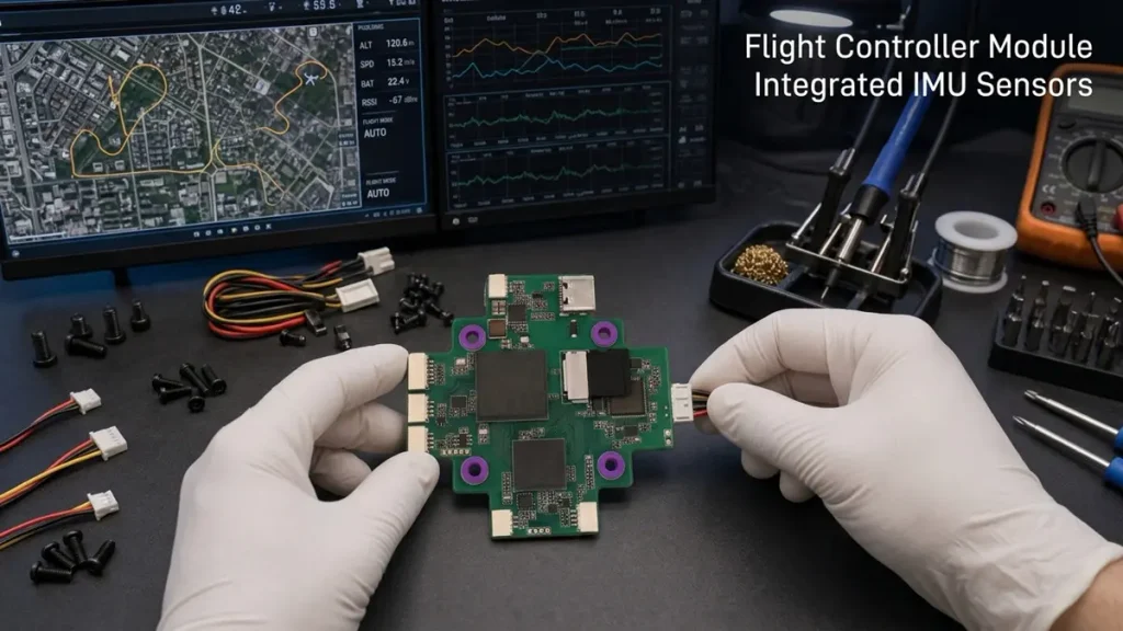
Gimbal Controller PCBA Assembly and Functional Testing
The appropriate PCBA inspection plan depends on component packages, product risk, assembly complexity, and customer acceptance criteria. AOI, X-ray, electrical tests, and functional tests serve different purposes and should be selected accordingly.
When Should You Use AOI or X-Ray Inspection?
Automated optical inspection (AOI) can help identify visible assembly defects, including component-placement errors, polarity issues, and certain soldering problems.
X-ray inspection may be appropriate for hidden solder joints, such as those beneath BGA packages or other components whose joints cannot be inspected optically.
Neither method replaces every other quality-control step. The inspection plan should identify which defects each method can detect and which risks require additional testing.
How Should SMT and Through-Hole Assembly Be Managed?
Surface-mount technology (SMT) is commonly used for compact control boards containing MCUs, sensors, power-management components, and passive devices.
Through-hole technology (THT) may be required for selected connectors, mounting components, or parts whose mechanical or electrical requirements justify that construction.
The assembly plan should define:
- Approved component manufacturers and part numbers.
- BOM revision and approved alternatives.
- Placement and polarity requirements.
- Stencil and solder-paste requirements.
- Reflow or other applicable soldering processes.
- Inspection criteria and rework requirements.
What Should Be Included in PCBA Functional Testing?
A suitable functional test plan should reflect the product’s actual interfaces and intended operating conditions.
Depending on the design, tests may include:
- Power-up and current-consumption checks.
- MCU programming and firmware verification.
- IMU communication and sensor-data acquisition.
- Communication-interface checks.
- Motor-driver enable and control-signal verification.
- Protection-circuit checks, where required.
- Functional operation under an agreed test setup.
Motor-driven testing should only be performed with appropriate fixtures, electrical protection, and operating procedures.
Calibration, closed-loop stabilization, and vibration testing may require dedicated fixtures or a complete mechanical assembly. These activities should be identified separately in the RFQ so that the supplier can quote the correct scope.
How Do You Qualify a Gimbal Controller PCB Manufacturer?
OEM buyers should evaluate a Gimbal Controller PCB manufacturer using documented capabilities, engineering responsiveness, manufacturing consistency, component sourcing, inspection processes, and production readiness.
The lowest bare-board price may not produce the lowest total cost if the project requires additional engineering changes, component substitutions, rework, or repeated validation.
Which PCB Fabrication Capabilities Should You Verify?
Confirm that the supplier can manufacture the actual design, including the required:
- Layer count and stackup.
- Finished copper thickness.
- Minimum trace and spacing.
- Finished hole sizes and aspect ratio.
- Board outline and dimensional tolerances.
- Surface finish and solder mask.
- Material grade and any controlled-impedance requirements.
Ask for confirmation against the supplied design files rather than relying exclusively on a general capability statement.
What Should a PCBA Supplier Include in a DFM Review?
A useful DFM review should identify manufacturability concerns before production.
It may include footprint checks, solder-mask clearances, component spacing, drill and annular-ring considerations, panelization, assembly access, and potential inspection limitations.
The review should also identify missing information, ambiguous drawings, and unapproved component alternatives.
For mixed PCB fabrication and assembly projects, agree on who is responsible for approving design changes and who has authority to release the production files.
How Should You Evaluate Component Sourcing and Traceability?
For turnkey PCBA, the supplier may be responsible for sourcing components in addition to fabricating the PCB and assembling the board.
Buyers should clarify:
- Whether quoted components are from approved manufacturers.
- How shortages and obsolete components are handled.
- Whether substitutions require written approval.
- What lot or date-code traceability is available.
- How BOM revisions are controlled.
- Which materials and test records can be provided with the order.
These controls are especially important when the controller is part of a product with formal reliability or customer-specific documentation requirements.
Why Choose Shenzhen Hongda Circuit Technology Co., Ltd.?
Shenzhen Hongda Circuit Technology Co., Ltd. provides PCB manufacturing and PCBA assembly services for customers developing custom electronic products.
For a gimbal controller project, the appropriate manufacturing scope should be established from the customer’s technical files, BOM, quantity, inspection requirements, and production objectives.
A project review should clarify:
- Bare-PCB fabrication requirements.
- SMT and through-hole assembly requirements.
- Material and component specifications.
- Engineering questions and DFM feedback.
- Inspection and functional-testing scope.
- Prototype, production, packaging, and delivery requirements.
Rather than assuming every gimbal controller design uses the same process, the project should be assessed against its actual requirements. Specific tolerances, lead times, certifications, test coverage, and production capabilities should be confirmed before quotation.
Explore the PCB manufacturer services page to review the relevant manufacturing service scope.
How Much Does a Custom Gimbal Controller PCB Cost?
The cost of a custom Gimbal Controller PCB depends on board construction, order quantity, material requirements, assembly complexity, component sourcing, testing, and delivery schedule. A bare-PCB quotation and a turnkey PCBA quotation cover different cost components and should not be compared as if they were equivalent.
Which Factors Have the Biggest Impact on PCB Cost?
| Cost factor | Why it matters |
|---|---|
| Board dimensions and layer count | Affect material usage, fabrication complexity, and panel utilization |
| Copper thickness and design rules | May require different manufacturing processes |
| PCB material and surface finish | Influence material cost and process requirements |
| Order quantity | Affects setup-cost allocation and production efficiency |
| Component count and package types | Affect placement, soldering, and inspection effort |
| BOM availability | Can influence procurement cost and schedule |
| Testing requirements | Add fixtures, engineering effort, and test time where applicable |
| Delivery schedule | May affect procurement and production planning |
| Packaging and logistics | Depend on shipping destination and handling requirements |
How Can OEM Buyers Reduce Cost Without Increasing Failure Risk?
The most effective approach is to optimize the design before releasing it for manufacturing.
Consider these actions:
- Select the minimum layer count that meets electrical and routing requirements.
- Avoid unnecessarily tight trace-and-space requirements.
- Use standard, available components where technically appropriate.
- Minimize avoidable package and footprint variations.
- Provide complete manufacturing files to reduce clarification cycles.
- Define required tests rather than paying for unrelated inspection services.
- Approve substitutions and design changes through a controlled process.
Cost optimization should not compromise IMU performance, power integrity, thermal limits, or required reliability.
For low-volume projects, compare the total cost of prototypes, assembly, test fixtures, engineering changes, and subsequent production rather than focusing only on the first board price.
How Can You Request a Gimbal Controller PCB Prototype or Production Quote?
To receive an accurate quote, provide the PCB fabrication files, BOM, assembly data, required quantity, technical specifications, and inspection requirements. Complete information helps the supplier evaluate manufacturability, component availability, assembly complexity, and delivery expectations.
Which Files Are Required for a PCB Manufacturing Quote?
For bare-PCB fabrication, prepare:
- Gerber or another mutually agreed fabrication-data format.
- NC drill files.
- Board outline and dimensional information.
- Layer stackup and copper-thickness requirements.
- Material and surface-finish specifications.
- Controlled-impedance requirements, if applicable.
- Fabrication notes and acceptance criteria.
The supplier should confirm any missing information before production release.
What Information Is Needed for a Turnkey PCBA Quote?
For assembly, provide:
- Complete BOM with manufacturer part numbers.
- Centroid or pick-and-place file.
- Assembly drawings and component polarity information.
- PCB fabrication files.
- Firmware or programming requirements, if applicable.
- Required functional tests and calibration procedures.
- Approved-vendor and component-substitution policies.
- Order quantity and target delivery date.
If the design uses a specialized IMU, motor driver, connector, or other critical component, identify the exact part number and any approved alternatives.
What Should You Confirm Before Approving Mass Production?
Before releasing the order, confirm:
- Final Gerber, drill, BOM, and assembly-data revisions.
- Agreed PCB materials, stackup, dimensions, and finish.
- Approved components and substitution policy.
- Assembly inspection and acceptance criteria.
- Functional test scope and responsibility.
- Prototype approval and any required engineering changes.
- Packaging, traceability, delivery terms, and documentation.
For new designs, a staged process—from prototype fabrication to assembly validation and production release—can help identify issues before larger quantities are committed.
Request a Gimbal Controller PCB Quote
Shenzhen Hongda Circuit Technology Co., Ltd. welcomes inquiries for custom PCB manufacturing and PCBA assembly projects.
To help evaluate your requirement, include the following information in your RFQ:
- Application: Drone gimbal, handheld stabilizer, industrial camera, robotic vision, or another product.
- Board requirements: Dimensions, layer count, thickness, copper weight, and material.
- Assembly scope: SMT, through-hole, turnkey component sourcing, or other required services.
- Order quantity: Prototype quantity and expected production demand.
- Testing: Electrical inspection, functional testing, programming, calibration, or other requirements.
- Target schedule: Requested prototype and production delivery dates.
Contact: pcb@pcbkr.com
Website: https://www.pcbkr.com/
Submit your design files and project requirements for a manufacturing review and quotation based on the actual scope of work.
Frequently Asked Questions
What Is a Gimbal Controller PCB?
A Gimbal Controller PCB is an electronic circuit board that processes motion-sensor information and controls motors to stabilize a camera or other payload. It typically integrates a microcontroller, IMU, motor-control circuitry, power management, and communication interfaces.
How Many PCB Layers Does a Gimbal Controller Need?
The required layer count depends on circuit complexity, routing density, electrical noise, and mechanical constraints. A two-layer board may suit a simpler design, while a four-layer board can provide more routing flexibility and reference-plane options. The final stackup should be selected after design review.
How Do You Reduce IMU Noise on a Gimbal Controller PCB?
Use appropriate sensor placement, power decoupling, controlled return paths, and separation from high-current switching loops. Verify performance with measurements under representative operating conditions. Mechanical vibration, sensor bias, and firmware behavior should also be evaluated because PCB layout alone cannot resolve every stabilization problem.
What Is the Difference Between a Gimbal Controller PCB and a Motor Driver PCB?
A gimbal controller PCB processes sensor data and calculates control commands. A motor driver PCB provides the electrical switching and current control required to operate the motors. The functions can be integrated on one PCB or distributed across separate boards depending on the design.
Can a Gimbal Controller PCB Be Customized for a Drone?
Yes. A custom design can be developed around the drone’s camera payload, gimbal axes, motor characteristics, IMU, available space, interfaces, power budget, and environmental requirements. The final design must be validated in the intended mechanical and electrical system.
What Tests Should Be Performed on a Gimbal Controller PCBA?
Typical checks may include power-up testing, current consumption, firmware programming, sensor communication, interface verification, and motor-control checks. AOI or X-ray may be used where appropriate for assembly inspection. Calibration and full stabilization testing depend on the project requirements and available fixtures.
How Much Does a Gimbal Controller PCB Cost?
There is no universal price because cost depends on board dimensions, layer count, copper thickness, materials, quantity, components, assembly complexity, and test requirements. Providing complete fabrication files and a BOM allows a supplier to prepare a more accurate quotation.
What Files Are Needed for a Gimbal Controller PCBA Quote?
A typical RFQ includes Gerber files, NC drill files, stackup specifications, a BOM with manufacturer part numbers, centroid data, assembly drawings, order quantity, and required test specifications. Additional information may be needed for programming, calibration, or specialized inspection.
Can a PCB Manufacturer Support Both Prototypes and Mass Production?
A manufacturer may support both stages, but the buyer should confirm the relevant fabrication capabilities, assembly processes, material sourcing, inspection controls, and production capacity. Prototype approval should include any required engineering changes before the production files are released.
How Do I Choose a Gimbal Controller PCB Assembly Supplier?
Compare suppliers on manufacturing capability, DFM support, component sourcing, revision control, inspection methods, functional testing, documentation, and total delivered cost. Confirm that the supplier can meet the actual technical requirements and clearly define the responsibilities of each party before placing the order.
Conclusion
Selecting a Gimbal Controller PCB manufacturer requires more than comparing board prices. OEM buyers should evaluate PCB architecture, IMU layout, power integrity, motor-drive noise, material selection, assembly quality, testing, and production consistency as parts of one engineering and procurement process.
Shenzhen Hongda Circuit Technology Co., Ltd. supports PCB manufacturing and PCBA assembly requirements for custom electronic products. By submitting complete design files, component information, quantities, and acceptance criteria, buyers can establish a clear project scope and obtain a quotation aligned with their manufacturing needs.
Ready to discuss your project? Email pcb@pcbkr.com or visit https://www.pcbkr.com/ to submit your Gimbal Controller PCB manufacturing or assembly inquiry.
About Author
David Chen (G) LinkedIn Profile
David Chen is a Senior RF/PCB Process Engineer at Shenzhen Hongda Circuit Technology Co., Ltd., with over 12 years of experience in high-frequency PCB fabrication, impedance-controlled stack-up design, and Rogers/PTFE laminate processing. He also boasts an extensive professional background in PCBA manufacturing, PCBA testing, and PCBA optimization, with specialized expertise in high-precision PCBA fault analysis and rigorous PCBA reliability testing. The author has worked with high-layer-count server PCB fabrication, ultra-low-loss backplane stackups, and thermo-mechanical reliability optimization for AI infrastructure projects involving 112G and 224G PAM4 architectures. Skilled in complex circuit design and cutting-edge advanced PCB manufacturing processes, he delivers solutions that elevate product durability and performance across industrial applications. His technical articles focusing on PCBA manufacturing workflows and testing methodologies are widely cited by industry peers and technical platforms, and have gained attention and recognition from industry colleagues.