Managing Thermal Expansion (CTE) in High-Tg FR4 PCBs to Prevent Delamination: A Procurement Engineer’s Guide to Supplier Evaluation and Material Reliability
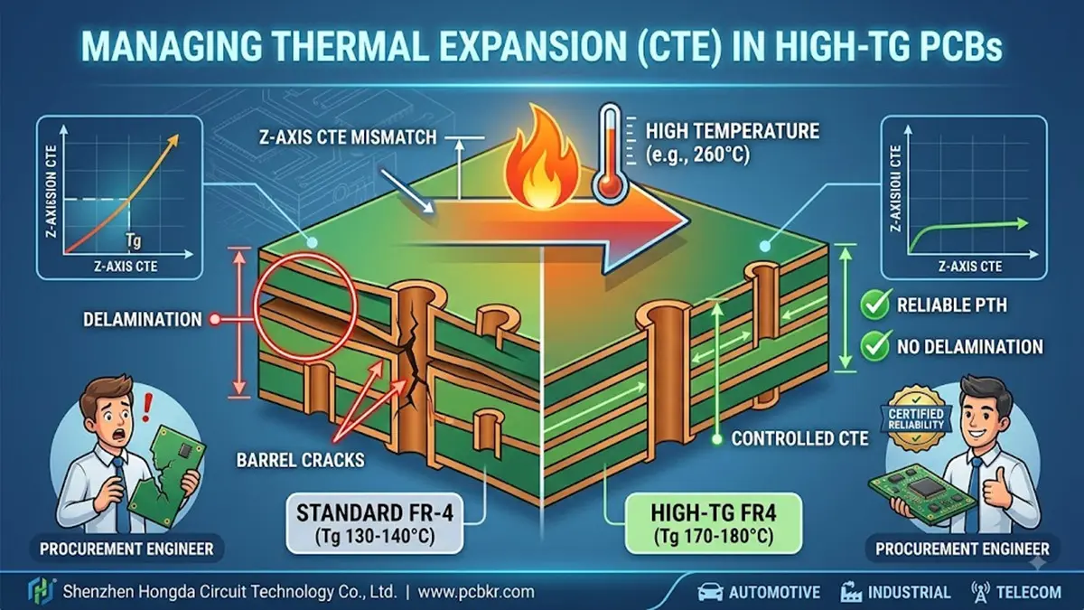
When a procurement engineer sources multilayer boards for automotive ECUs, industrial power converters, or telecom base stations, one specification often gets overlooked until field failures force a redesign: the coefficient of thermal expansion (CTE). Standard FR-4 laminates with glass transition temperatures (Tg) around 130–140°C may look cost-effective on the RFQ, but they carry hidden liability. In lead-free reflow environments reaching 260°C peak, the Z-axis CTE of conventional FR-4 can spike to 250–350 ppm/°C above Tg—roughly 15× the expansion rate of copper barrels inside plated through-holes (PTHs). The result? Barrel cracks, pad lifting, and layer delamination that surface months after deployment.
This guide addresses the full procurement decision chain—from material specification and supplier capability assessment to incoming quality verification—so buyers can lock in reliable High-Tg PCB fabrication partners before the first prototype ships.
What Is CTE and Why Z-Axis Expansion Is the Silent Killer in High-Reliability Assemblies
Every PCB laminate expands when heated. Engineers typically worry about X/Y plane expansion because it affects component alignment. But for procurement professionals evaluating High-Tg FR4 PCB suppliers, the critical metric is Z-axis CTE—the expansion through the board’s thickness. This is where catastrophic failures originate.
The Physics of PTH Barrel Cracking and Interconnect Fracture
Copper plating inside a drilled hole expands at approximately 16–18 ppm/°C. Standard FR-4 epoxy, once heated past its Tg, can expand at 55–60 ppm/°C below Tg and surge far higher above it. During thermal cycling—whether from reflow soldering, power cycling, or outdoor temperature swings—this mismatch generates repeated tensile and compressive stress on PTH barrels. Over time, fatigue cracks initiate at the knee of the barrel and propagate inward, creating intermittent opens that are nearly impossible to diagnose in the field.
For buyers sourcing multilayer High-Tg PCBs for industrial controllers or automotive modules, this failure mode translates to warranty claims, recalls, and damaged customer relationships. The larger the board thickness and the higher the layer count, the more severe the cumulative Z-axis stress becomes.
How Moisture Amplifies CTE-Driven Delamination Risk
Moisture trapped within the epoxy resin matrix vaporizes rapidly when exposed to reflow temperatures above 240°C. The resulting steam pressure, combined with softened resin above Tg, can exceed interlaminar bond strength and cause measurable delamination—even in boards that passed electrical test at ambient temperature.
This is why a High-Tg PCB manufacturer’s moisture control protocol is not a secondary detail. It is a primary determinant of whether your boards survive three reflow passes, a selective solder operation, and a decade of field thermal cycling.
How High-Tg Materials Reduce Z-Axis CTE and Extend Board Lifespan
Raising Tg from 140°C to 170–180°C fundamentally changes the resin’s molecular structure. Cross-linked epoxy systems used in High-Tg FR4 PCB materials maintain higher storage modulus above Tg, which directly suppresses Z-axis expansion. The practical effect: PTH barrels experience lower cyclic stress, solder joints under large BGAs see reduced shear displacement, and internal layers resist separation during peak assembly temperatures.
Material Selection Matrix for Procurement Teams
| Material Grade | Typical Tg | Z-Axis CTE (Above Tg) | Best Fit Application | Relative Cost Position |
|---|---|---|---|---|
| Standard FR-4 | 130–140°C | 250–350 ppm/°C | Consumer electronics, low-stress environments | Baseline |
| Mid-Tg FR-4 | 150–170°C | 180–250 ppm/°C | General industrial, LED drivers | +10–15% |
| High-Tg FR-4 | 170–180°C | 120–180 ppm/°C | Automotive ECUs, telecom, power electronics | +20–30% |
| Ultra High-Tg / BT Resin | 180–200°C+ | 80–120 ppm/°C | Aerospace, EV battery management, military | +40–60% |
For procurement engineers evaluating High-Tg PCB fabrication services, the takeaway is clear: Tg alone does not tell the full story. You must also verify the supplier’s access to laminates with low Z-axis CTE, high decomposition temperature (Td), and controlled dielectric properties if the design includes impedance-sensitive traces.
The Lead-Free Assembly Imperative Driving High-Tg Adoption
RoHS-mandated lead-free solders require reflow peak temperatures of 240–260°C. Standard FR-4 enters its rubbery transition state during every solder joint formation, consuming a significant portion of the board’s thermal fatigue budget before the product ever reaches the end customer. Industry data indicates that three assembly cycles above Tg can equate to over 1,000 subsequent thermal cycles to 80°C in terms of accumulated damage.
When a buyer requests reliable High-Tg PCB fabrication for lead-free assemblies, they are not buying a luxury material. They are purchasing insurance against latent defects that standard FR-4 cannot economically prevent.
Manufacturing Practices That Separate Reliable High-Tg PCB Suppliers from Commodity Fabricators
Not every factory that claims High-Tg PCB manufacturing capability delivers the same reliability outcome. The lamination cycle, moisture management protocol, and inspection infrastructure determine whether a High-Tg board achieves its theoretical performance or fails prematurely. Here is what procurement teams should verify during supplier audits and RFQ reviews.
Controlled Lamination Cycles and Optimized Cooling Rates
High-Tg prepregs require slower heating ramps—typically 2–4°C per minute—to allow resin flow without void entrapment. Press dwell time at target cure temperature must extend 60–120 minutes depending on stack-up thickness, followed by a controlled cooling phase that prevents internal stress lock-in.
At Shenzhen Hongda Circuit Technology, our multilayer presses operate with programmable multi-zone thermal profiles and vacuum-assisted lamination. This eliminates internal voids—a preferential site for moisture entrapment—and ensures uniform cure across 4-layer to 20-layer stack-ups. For buyers sourcing High-Tg multilayer PCBs, vacuum lamination is not optional; it is the difference between a board that passes IST testing and one that develops barrel cracks after 200 thermal cycles.
Pre-Lamination Baking and Moisture Barrier Protocols
High-Tg laminates and prepregs must be baked at 105–125°C for 4–8 hours before lay-up if they have been exposed to ambient humidity during storage. Post-etch inner layers receive a secondary bake at 125°C for 2 hours to remove processing moisture. Finished boards are sealed in moisture barrier bags (MBB) with desiccant and humidity indicator cards (HIC) compliant with IPC-1601.
Procurement tip: Ask your High-Tg PCB supplier to document bake logs and HIC readings for every lot. A factory that treats moisture control as paperwork rather than physics will eventually ship delaminated boards.
Advanced Drilling and Desmear for High Aspect Ratio PTHs
High-Tg resins are harder than standard FR-4, which increases drilling temperatures and raises the risk of epoxy smear inside holes. Smear that is not fully removed during the desmear process blocks electroless copper from adhering to inner layer pads, creating latent opens. Our facility uses high-speed CNC drilling with controlled entry/exit materials, followed by plasma desmear for high-layer-count boards and concentrated permanganate chemistry for standard builds. This dual-path approach ensures copper barrel integrity on aspect ratios up to 12:1.
3D AOI, SPI, and X-Ray Inspection as Standard Infrastructure
In 2026, defect detection has migrated from sample-based manual inspection to 100% automated coverage. 3D solder paste inspection (SPI) catches insufficient paste volume before placement; 3D AOI verifies component coplanarity and solder fillet geometry after reflow; and 3D X-ray tomography reveals voids, cracks, and insufficient barrel fill in hidden joints.
Shenzhen Hongda Circuit Technology integrates AOI + SPI + X-Ray inspection chains on all High-Tg production lines. For procurement teams evaluating High-Tg PCB assembly services, this closed-loop architecture means first-pass yield improvements of 8–15 percentage points and defect escape rates below 50 DPM—critical metrics when supplying automotive Tier-1 or medical device OEMs.
Testing Reliability: Thermal Stress, Solder Float, and IST Validation
A supplier’s self-reported capability means nothing without standardized test data. When auditing High-Tg PCB manufacturers, demand objective evidence from the following test protocols.
Thermal Shock and T288 Delamination Resistance
Thermal shock testing subjects boards to rapid transitions between temperature extremes—typically -65°C to +125°C or -55°C to +150°C per IPC-TM-650 Method 2.6.7.2. T288 testing measures the time to delamination when a laminate sample is held at 288°C. Premium High-Tg materials should survive T288 for greater than 5 minutes; advanced formulations exceed 30 minutes.
Interconnect Stress Test (IST) for PTH Barrel Integrity
IST accelerates via barrel cracking through rapid thermal cycling (typically 25°C to 150°C) while monitoring resistance changes in daisy-chained PTH networks. A 10% resistance increase indicates failure. For automotive and aerospace procurement specs, require IST data showing minimum cycle counts before failure—often 300+ cycles for High-Tg builds versus fewer than 100 for standard FR-4.
Solder Float and Lead-Free Reflow Simulation
Solder float testing immerses board samples in molten solder at 288°C for 10 seconds per IPC-TM-650 Method 2.4.13. Boards must show no blistering, delamination, or measling. For lead-free process validation, many buyers now specify three-pass reflow simulation (peak 260°C) followed by cross-sectional analysis of PTH barrels and microvias.
The Procurement Decision Framework: How to Vet a High-Tg PCB Fabrication Partner
Selecting a reliable High-Tg PCB manufacturer is not a price-only exercise. The following decision matrix aligns technical requirements with supplier capability tiers, helping procurement teams move from RFQ to PO with confidence.
Tier 1 Evaluation—Material Traceability and Certifications
| Checkpoint | What to Verify | Red Flag |
|---|---|---|
| Laminate sourcing | Direct relationships with Isola, Ventec, NanYa, or Kingboard; lot traceability | Vague “FR-4 equivalent” claims without mill certificates |
| Certifications | ISO 9001, ISO 14001, IATF 16949 (automotive), UL recognition | Missing automotive or medical certs for regulated applications |
| IPC compliance | IPC-6012 Class 2 or 3, IPC-A-600 acceptability, IPC-4101 material specs | No documented workmanship standards |
| Material storage | Climate-controlled dry cabinets (<50% RH, <23°C) for prepregs | Prepregs stored in open warehouse conditions |
Tier 2 Evaluation—Process Control and Equipment
| Checkpoint | What to Verify | Red Flag |
|---|---|---|
| Lamination press | Multi-zone vacuum presses with data-logged temperature/pressure profiles | Single-zone presses without vacuum capability |
| Drilling | High-speed spindle CNC, laser drilling for microvias | Outdated mechanical-only drilling for HDI features |
| Inspection | 3D AOI, 3D SPI, X-Ray (2D and 3D CT) on production lines | Manual visual inspection as primary QA method |
| Baking | Dedicated forced-air convection ovens with temperature accuracy ±5°C | Kitchen ovens or shared curing equipment |
Tier 3 Evaluation—Engineering Support and Responsiveness
| Checkpoint | What to Verify | Red Flag |
|---|---|---|
| DFM review | Stack-up optimization, impedance modeling, material recommendations | No engineering feedback; straight-to-fab without review |
| Prototype agility | 24–72 hour quick-turn capability for NPI validation | 2-week minimum for any prototype order |
| Documentation | Full COA, cross-section photos, IST/T288 reports per lot | Generic “passed test” statements without data |
| Communication | Dedicated account engineer fluent in technical English | Only sales contact with no technical depth |
Why Shenzhen Hongda Circuit Technology for Your High-Tg PCB Requirements
Shenzhen Hongda Circuit Technology Co., Ltd. (www.pcbkr.com) operates a 35,000-square-meter facility equipped for High-Tg FR4 PCB fabrication from prototype through high-volume production. Our technical platform includes:
- Material range: Tg 150°C, 170°C, and 180°C FR-4; halogen-free High-Tg; and hybrid low-loss/High-Tg laminates for 5G and RF applications
- Layer capability: 2 to 20+ layers with controlled impedance, blind/buried vias, and stacked microvia HDI structures
- Copper weight: 0.5 oz to 13 oz finished copper for high-current industrial designs
- Inspection infrastructure: Full 3D AOI, 3D SPI, and X-Ray inspection with AI-enhanced defect classification; MES-integrated traceability for automotive and medical compliance
- Thermal validation: In-house T288, solder float, and thermal shock testing; IST capability through partner labs
- Certifications: ISO 9001, ISO 14001, UL recognized, with IATF 16949 alignment in progress for automotive programs
We do not treat High-Tg as a material upsell. We treat it as a reliability specification that must be earned through process discipline, equipment investment, and data transparency. Every High-Tg quote includes a DFM review, recommended stack-up, and material datasheet. Every production lot ships with a certificate of analysis and thermal test summary.
Frequently Asked Questions—What PCB Procurement Buyers Search on Google
How do I know if my application actually needs High-Tg PCB material instead of standard FR-4?
You need High-Tg FR4 when your board will experience (a) lead-free reflow peak temperatures above 240°C, (b) continuous operating temperatures above 110°C, (c) multiple thermal cycles during assembly or field use, or (d) thick multilayer construction (8+ layers) where cumulative Z-axis stress is significant. Automotive under-hood electronics, industrial motor drives, telecom base stations, and LED power supplies are typical applications where standard FR-4 failure rates become unacceptable. If your product requires a 10-year field life or carries safety-critical functions, High-Tg is the conservative engineering choice.
What certifications should I demand from a High-Tg PCB manufacturer before placing a production order?
At minimum, require ISO 9001 for quality management and IPC-6012 Class 2 (commercial) or Class 3 (high-reliability) for workmanship. For automotive applications, IATF 16949 is mandatory. For medical devices, ISO 13485 and FDA registration of the facility are standard expectations. Additionally, verify UL recognition for the specific laminate grades being used, and request material mill certificates to confirm Tg, Td, and CTE values match your specification. A supplier that cannot produce these documents on demand is a supplier that cannot guarantee consistency.
How can I verify that my supplier’s High-Tg boards will not delaminate during lead-free assembly?
Request three objective data points before production: (1) T288 delamination resistance time for the exact laminate lot, (2) solder float test results at 288°C for 10 seconds per IPC-TM-650, and (3) a written moisture control protocol showing bake temperatures, durations, and packaging standards (IPC-1601). For high-reliability programs, add IST or thermal shock cycle data. At Shenzhen Hongda Circuit Technology, we provide all four data sets as standard documentation for every High-Tg production lot.
What is the real cost difference between standard FR-4 and High-Tg FR-4, and is it justified?
High-Tg FR-4 typically adds 20–35% to raw laminate cost, which translates to 10–20% at the finished board level depending on layer count and copper weight. However, this premium must be weighed against the total cost of failure: field returns, warranty repairs, redesign cycles, and brand damage. In automotive and industrial applications, the laminate upcharge is usually negligible compared to the cost of a single recall. For high-volume consumer electronics with benign thermal environments, standard FR-4 remains appropriate. The key is matching material grade to actual thermal stress, not defaulting to the cheapest option.
What advanced inspection technologies should a High-Tg PCB supplier have in 2026?
By 2026, a capable High-Tg PCB fabricator and assembly partner should operate 3D SPI for paste deposition control, 3D AOI with AI classification for post-reflow surface inspection, and X-Ray inspection (2D and 3D CT) for hidden solder joints, BGA voids, and PTH barrel integrity. These systems should be MES-integrated to provide lot-level traceability. Manual visual inspection is no longer sufficient for boards carrying 01005 passives, 0.3 mm-pitch BGAs, or stacked microvias. Ask for equipment lists and defect escape rate data during your supplier qualification audit.
Ready to eliminate thermal expansion risk from your next PCB program?
Contact Shenzhen Hongda Circuit Technology Co., Ltd. at www.pcbkr.com for a free DFM review, material recommendation, and competitive quotation on reliable High-Tg PCB fabrication tailored to your thermal reliability requirements.
About Author
David Chen https://www.linkedin.com/in/pcbcoming
David Chen boasts an extensive professional background in PCBA manufacturing, PCBA testing, and PCBA optimization, with specialized expertise in high-precision PCBA fault analysis and rigorous PCBA reliability testing. The author has worked with high-layer-count server PCB fabrication, ultra-low-loss backplane stackups, and thermo-mechanical reliability optimization for AI infrastructure projects involving 112G and 224G PAM4 architectures. Skilled in complex circuit design and cutting-edge advanced PCB manufacturing processes, he delivers solutions that elevate product durability and performance across industrial applications. His technical articles focusing on PCBA manufacturing workflows and testing methodologies are widely cited by industry peers, research institutions, and technical platforms, solidifying his reputation as a recognized technical authority in the global circuit board manufacturing sector.