What Should OEMs Know When Sourcing Server Hard Disk Backplane PCBA?
A Server Hard Disk Backplane PCBA connects multiple HDDs or SSDs to a server or storage system through data, power, and management interfaces. For OEMs, sourcing a reliable backplane requires more than component assembly: PCB fabrication, connector accuracy, signal integrity, solder quality, and inspection must be considered together. A turnkey manufacturer can coordinate bare-board production and PCBA assembly under one manufacturing process.
What Is a Server Hard Disk Backplane PCBA?
A server hard disk backplane PCBA is an assembled circuit board installed behind or alongside a server’s drive bays. It provides the electrical and mechanical connection between installed storage devices and the server’s motherboard, RAID controller, host bus adapter, or storage infrastructure.
Unlike a conventional control board, a storage backplane often combines several functions on one assembly:
- Data connectivity: Routes signals between HDDs or SSDs and the host system.
- Power distribution: Supplies operating power to installed drives through the specified power architecture.
- Drive management: Supports functions such as drive presence detection, status indication, and management signals when included in the design.
- Mechanical integration: Positions drive connectors and mounting features to match the chassis and drive carriers.
- Serviceability: Supports drive installation and replacement, including hot-swap operation when the complete system design provides it.
The exact architecture depends on the server platform, drive interface, number of drive bays, controller design, and chassis requirements.
For OEM procurement, it is important to specify the complete PCBA rather than describing the project only as a bare server backplane PCB. The manufacturing requirements include both the fabricated board and the assembled components.
What Types of Server Hard Disk Backplane PCBA Are Used in Storage Systems?
The main product categories are determined by the storage interface, drive form factor, and system architecture.
SAS HDD Backplane PCBA
A SAS backplane connects SAS drives to a compatible SAS controller or expander architecture. Depending on the design, it may include high-density connectors, signal-routing structures, drive-status circuits, and management interfaces.
Important sourcing considerations include:
- The specified SAS generation and data-rate requirements.
- Connector part numbers and mechanical positioning.
- Differential impedance and routing requirements.
- Power distribution and grounding.
- Expander and management circuitry, if included in the design.
The PCB stack-up and routing rules should be reviewed against the actual interface and system design. A generic multilayer PCB specification is not sufficient to establish signal integrity.
SATA Hard Drive Backplane PCBA
A SATA backplane connects SATA HDDs or SSDs to the host system. It may be designed for individual drive connections or a multi-drive storage configuration.
OEMs should confirm the SATA interface requirements, connector layout, drive power arrangement, and any required drive-presence or status-indication functions before production.
NVMe SSD Backplane PCBA
An NVMe backplane is designed for SSDs using PCIe-based connectivity. Depending on the system, it may support U.2, U.3, or other specified drive form factors and connector standards.
Compared with a conventional SATA backplane, an NVMe design can place greater emphasis on high-speed differential routing, insertion loss, crosstalk, return paths, and connector transitions.
The applicable PCIe generation, lane configuration, routing constraints, and impedance targets must come from the customer’s released design documentation. They should not be assumed from the product name alone.
Hot-Swap Drive Backplane PCBA
A hot-swap backplane is designed to allow supported drives to be inserted or removed while the system remains powered. This is a system-level function, not simply a PCB feature.
Depending on the platform, the design may include drive-presence detection, power sequencing, status indicators, management signals, and compatible connectors.
The backplane assembly must meet the mechanical, electrical, and interface requirements defined by the server OEM. Final hot-swap validation should be performed against the customer’s system-level test procedure.
What Are the Critical Components in a Server Hard Disk Backplane PCBA?
The bill of materials and component placement determine the assembly process, inspection requirements, and manufacturing risks.
| Component or design area | Manufacturing consideration | Information to confirm |
|---|---|---|
| SAS, SATA, or PCIe connectors | Positioning, solder joints, coplanarity, and mechanical strength | Exact manufacturer part number and drawing |
| Power connectors | Solder integrity and current-carrying requirements | Current rating, pin assignment, and mounting method |
| Management ICs | Correct component orientation and solder quality | BOM, package, and assembly notes |
| BGA or fine-pitch ICs, if used | Hidden solder-joint inspection and process control | Package drawing and inspection criteria |
| Passive components | Placement accuracy and polarity where applicable | BOM and pick-and-place data |
| LEDs and drive-status circuits | Correct placement and polarity | Circuit diagram and functional requirements |
| PCB stack-up and copper design | Impedance, power distribution, and manufacturability | Stack-up, copper thickness, and controlled-impedance requirements |
High-density connectors deserve particular attention. Their mechanical alignment must match the drive carrier and chassis, while their solder joints must withstand the stresses associated with installation and service.
For components with hidden solder joints, such as BGA packages, the inspection plan should be selected according to the package, board design, and customer quality requirements.
How Does PCB Fabrication Affect Server Hard Disk Backplane PCBA Reliability?
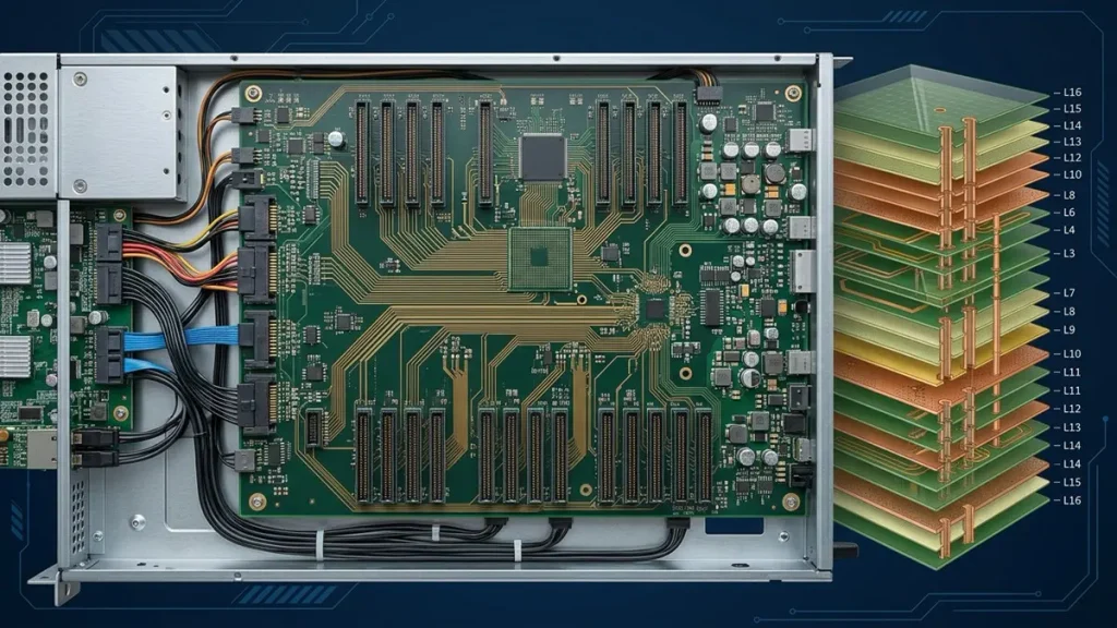
Server Hard Disk Backplane PCBA multilayer PCB fabrication with high-speed routing and power distribution
The quality of the assembled backplane starts with the quality of the bare PCB. A defect introduced during fabrication can affect connector alignment, electrical performance, solderability, or long-term reliability.
How Does PCB Stack-Up Affect High-Speed Signal Transmission?
SAS and PCIe-based backplanes may require controlled-impedance differential routing. The stack-up must be designed around the interface requirements, material properties, copper thickness, dielectric thickness, and routing geometry.
During fabrication, variations in dielectric thickness, copper characteristics, and layer registration can affect the final electrical structure.
For projects with controlled-impedance requirements, OEMs should provide:
- Approved stack-up or stack-up design constraints.
- Target differential and single-ended impedance values, where applicable.
- Routing and reference-plane requirements.
- Material requirements or approved material alternatives.
- Impedance test coupons and acceptance criteria, if specified.
PCBKR’s high-speed PCB manufacturing capabilities can be reviewed on the High-Speed PCB page. Actual material selection, stack-up, and impedance controls must be confirmed for each backplane design.
Why Do Layer Registration and Via Quality Matter?
Multilayer backplanes may contain dense connector fan-outs, signal transitions, and power-distribution structures. Layer-to-layer registration and via quality therefore need to be controlled within the released fabrication requirements.
PCBKR uses SCREEN Ledia LDI equipment with an 8 μm target resolution and a stated ±10 μm process capability specification. Mitsubishi UV/CO₂ laser drilling supports 75 μm ±5 μm microvia processing, while picosecond laser processing supports 50 μm features.
These figures describe specific equipment and process capabilities; they do not mean every server backplane requires microvias or that every design can automatically use the smallest feature size. The appropriate fabrication process depends on the actual stack-up, drill structure, design rules, and manufacturability review.
For designs requiring HDI structures, see HDI PCB Manufacturing.
How Does Copper Design Affect Drive Power Distribution?
A multi-drive backplane may distribute power to several storage devices. The copper thickness, trace geometry, connector ratings, thermal conditions, and current distribution must be evaluated together.
For higher-current designs, OEMs should provide the expected operating current, peak current, voltage-drop limits, temperature requirements, and connector specifications.
Heavy copper may be appropriate for certain power-distribution sections, but it should not be treated as a universal solution. Copper thickness and trace dimensions must be selected according to the electrical and thermal design.
See Heavy Copper PCB Manufacturing for related fabrication capabilities.
What PCBA Assembly Challenges Should OEMs Consider?
Server backplane assembly often combines large connectors, dense component placement, and potentially fine-pitch or high-density packages. The assembly process must account for both electrical performance and mechanical fit.
How Should High-Density Connectors Be Assembled?
Connectors are among the most important components on a server backplane because they establish the electrical and mechanical interface with drives, cables, or the host system.
Before assembly, the manufacturer should review:
- Connector part numbers and approved alternatives.
- SMT, through-hole, or mixed-technology mounting requirements.
- Connector orientation and polarity.
- Positioning tolerances and mechanical drawings.
- Solder-joint acceptance criteria.
- Any post-assembly mechanical inspection requirements.
Through-hole connectors may require wave soldering, selective soldering, or another process selected according to the board layout and component requirements. SMT connectors require an appropriate solder-paste, placement, and reflow process.
The correct process should be determined from the actual PCB and component design rather than assumed from the product category.
How Should BGA and Fine-Pitch Components Be Controlled?
Where BGA or fine-pitch components are present, solder-paste deposition, placement accuracy, reflow conditions, pad design, and inspection become important process considerations.
PCBKR uses 3D AOI and X-ray inspection equipment. AOI can identify visible assembly defects, while X-ray inspection can help examine hidden solder joints in suitable packages.
The inspection method and acceptance criteria should be agreed upon according to the component package and customer quality requirements. Inspection equipment does not, by itself, establish that a board meets all system-level electrical or functional requirements.
Why Is Component Sourcing Part of Turnkey Manufacturing?
A turnkey project requires coordination between PCB fabrication and component procurement. Incorrect, substituted, obsolete, or unavailable components can delay production or introduce compatibility risks.
Before production, the OEM and manufacturer should confirm:
- Approved manufacturer and part numbers.
- Authorized or customer-approved sourcing channels.
- Alternative-component approval procedures.
- Lifecycle and availability concerns.
- Moisture sensitivity and storage requirements where applicable.
- Customer-supplied versus manufacturer-sourced components.
No component substitution should be made without the approval required by the customer’s engineering and procurement process.
What Tests Should a Server Hard Disk Backplane PCBA Pass Before Delivery?
The inspection and test plan should be based on the product design, component packages, customer specifications, and intended application.
A typical manufacturing quality plan may include the following stages:
| Inspection or test | What it checks | Important limitation |
|---|---|---|
| Incoming material inspection | PCB, components, and supplied materials against purchasing requirements | Does not verify complete board functionality |
| 3D AOI | Visible component placement, polarity, and solder-related defects | Cannot inspect every hidden solder joint |
| X-ray inspection | Suitable hidden solder joints and internal assembly features | Does not prove protocol compatibility |
| Electrical continuity and isolation testing | Opens, shorts, and specified electrical connections | Does not replace system-level testing |
| Four-wire Kelvin measurement | Low-resistance measurements where specified | Not a SAS, SATA, or NVMe functional test |
| Connector and mechanical inspection | Connector position, mounting, and visible mechanical conditions | Final chassis fit may require customer-level verification |
| Customer-specific functional testing | Functions defined by the approved test procedure | Requires an agreed test specification and suitable test setup |
For high-speed storage backplanes, electrical design verification may also involve impedance measurement, TDR, or VNA-based evaluation when required by the project specification.
PCBKR has VNA measurement capability up to 70 GHz. The relevant test method, fixture, frequency range, test coupon, and acceptance limits must be agreed for each project.
An important distinction for OEMs: AOI, X-ray, continuity testing, and low-resistance measurement are manufacturing inspection or electrical test methods. They do not automatically verify SAS, SATA, or NVMe protocol compliance, drive interoperability, hot-swap behavior, or compatibility with a specific server platform. Those functions require an appropriate customer-defined test setup and acceptance procedure.
How Should OEMs Select a Turnkey Server Hard Disk Backplane PCBA Manufacturer?
A suitable supplier should be able to coordinate PCB fabrication and PCBA assembly while understanding the electrical, mechanical, and quality requirements of the backplane.
OEMs should evaluate the following areas before approving a supplier:
- Turnkey manufacturing scope: Can the supplier manage bare PCB fabrication and component assembly under one project?
- Multilayer PCB capability: Can the supplier manufacture the required layer count, stack-up, copper thickness, and via structure?
- High-speed fabrication controls: Can the supplier review and manufacture controlled-impedance designs according to the approved specifications?
- Connector assembly experience: Can the supplier handle the specified SMT, through-hole, or mixed-technology connectors?
- Inspection resources: Are AOI, X-ray, and suitable electrical inspection methods available for the actual assembly?
- Engineering review: Can the supplier identify fabrication, assembly, component, and test risks before production?
- Production flexibility: Can the supplier review prototype, small-batch, and mass-production requirements?
- Quality documentation: Can the supplier provide the inspection records and manufacturing documentation required by the OEM?
A supplier should not be selected solely on the basis of a claimed layer count or minimum line width. The more important question is whether the supplier can manufacture the customer’s specific design consistently and verify it against the agreed acceptance criteria.
Why Choose PCBKR for Turnkey Server Hard Disk Backplane PCBA Manufacturing?
Shenzhen Hongda Circuit Technology Co., Ltd. provides PCB fabrication and PCBA assembly as a coordinated manufacturing service. This turnkey model gives OEMs one manufacturing partner for bare-board production and component assembly.
For server storage backplane projects, the manufacturing scope can be evaluated around the following requirements:
PCB fabrication
- Multilayer PCB manufacturing based on the approved Gerber or ODB++ data and stack-up.
- HDI and microvia processing where required by the design.
- Controlled-impedance fabrication according to the released electrical specifications.
- Copper thickness and power-distribution structures selected for the project requirements.
- Fabrication review before production.
PCBA assembly
- SMT and through-hole assembly according to the approved BOM and assembly files.
- Connector and high-density component placement.
- Component sourcing and procurement coordination for turnkey projects.
- 3D AOI and X-ray inspection where appropriate.
- Electrical inspection and customer-defined test coordination.
Manufacturing equipment and process resources
PCBKR’s manufacturing resources include SCREEN Ledia LDI, Mitsubishi UV/CO₂ laser drilling, LAUFFER vacuum lamination, 3D AOI, X-ray inspection, four-wire Kelvin measurement, and VNA measurement capability.
The equipment and process selected for a project depend on the board design and its manufacturing requirements. Not every backplane requires HDI, microvias, heavy copper, or high-frequency measurement.
For a broader overview of manufacturing resources and process capabilities, visit the PCBKR Capability page.
PCBKR supports prototype, small-batch, and mass-production requirements subject to project review, material availability, and manufacturing feasibility.
The final manufacturing and inspection plan should be confirmed against the customer’s released design files, quality requirements, and test specifications.
What Information Should You Provide for a Server Hard Disk Backplane PCBA Quote?
A complete RFQ package helps the manufacturer evaluate PCB fabrication, component sourcing, assembly complexity, inspection requirements, and production lead time.
For a turnkey quotation, prepare the following information where available:
| Required information | Purpose |
|---|---|
| Gerber or ODB++ files | Bare PCB fabrication review |
| PCB stack-up | Layer structure, material, and thickness evaluation |
| BOM | Component identification, sourcing, and cost estimation |
| Pick-and-place files | SMT assembly programming |
| Assembly drawings | Component orientation and assembly requirements |
| Mechanical drawings | Connector positions, mounting holes, and chassis interfaces |
| Impedance requirements | Controlled-impedance fabrication and verification |
| Drill and via specifications | Fabrication process evaluation |
| Connector part numbers | Component availability and assembly review |
| Inspection and test requirements | Quality planning and quotation scope |
| Prototype and production quantities | Pricing and production planning |
| Target delivery date | Material and capacity planning |
If the design is still under development, provide the available schematic, preliminary PCB data, mechanical drawings, and interface requirements. The manufacturing team can then identify missing information and potential DFM issues before production.
Request a turnkey quotation: Send your Gerber or ODB++ files, BOM, assembly data, target quantities, and required delivery schedule to sales@pcbkr.com.
PCBKR can review the complete PCB fabrication and PCBA assembly scope for your server hard disk backplane project.
Frequently Asked Questions About Server Hard Disk Backplane PCBA
Can PCBKR Provide Both PCB Fabrication and PCBA Assembly?
Yes. PCBKR’s project scope can cover bare PCB fabrication and PCBA assembly as a coordinated turnkey manufacturing service. The exact manufacturing process, materials, component sourcing, and inspection plan are confirmed after reviewing the project files.
Can You Manufacture SAS, SATA, and NVMe Backplane Assemblies?
Projects using SAS, SATA, or NVMe interfaces can be reviewed according to their PCB design, component list, stack-up, connector requirements, and assembly specifications. Interface support at the product level does not automatically mean that every protocol or server-platform compatibility test is included.
Can You Support Prototype and Small-Batch Production?
PCBKR supports prototype, small-batch, and mass-production requirements, subject to design review, component availability, and manufacturing feasibility. Include the expected quantities and production schedule in your RFQ.
How Do You Verify the Quality of a Server Backplane PCBA?
The inspection plan may include incoming material checks, 3D AOI, X-ray inspection for suitable packages, electrical testing, and other customer-specified inspections. Any functional or protocol-level test should be defined separately with its test method and acceptance criteria.
What Determines the Cost and Lead Time of a Turnkey Backplane PCBA?
The main factors include PCB layer count, material, board dimensions, copper thickness, impedance requirements, via structure, connector types, component package density, BOM availability, assembly process, inspection requirements, and order quantity. Complete Gerber or ODB++ data and BOM information allow a more accurate quotation.
About the Author
David Chen LinkedIn Profile
David Chen is a Senior RF/PCB Process Engineer at Shenzhen Hongda Circuit Technology Co., Ltd., with over 12 years of experience in high-frequency PCB fabrication, impedance-controlled stack-up design, and Rogers/PTFE laminate processing. He also boasts an extensive professional background in PCBA manufacturing, PCBA testing, and PCBA optimization, with specialized expertise in high-precision PCBA fault analysis and rigorous PCBA reliability testing. The author has worked with high-layer-count server PCB fabrication, ultra-low-loss backplane stackups, and thermo-mechanical reliability optimization for AI infrastructure projects involving 112G and 224G PAM4 architectures. Skilled in complex circuit design and cutting-edge advanced PCB manufacturing processes, he delivers solutions that elevate product durability and performance across industrial applications. His technical articles focusing on PCBA manufacturing workflows and testing methodologies are widely cited by industry peers and technical platforms, and have gained attention and recognition from industry colleagues.
Contact Shenzhen Hongda Circuit Technology Co., Ltd.
Email: sales@pcbkr.com
Website: www.pcbkr.com