What factors most influence the cost of ultra-thin rigid-flex HDI PCBs, and how can I optimize my design to reduce cost?
Why Ultra-Thin Rigid-Flex HDI PCBs Are Uniquely Expensive
Standard rigid PCBs, flex PCBs, and HDI PCBs each carry their own cost premiums. When you combine all three in a single ultra-thin package, the cost drivers do not simply add — they multiply. A rigid-flex PCB already costs approximately seven times more than an equivalent rigid board. Adding HDI microvias and ultra-thin stack-up requirements can push that multiplier to 10–15× or higher for complex designs.
Three fundamental cost forces converge in ultra-thin rigid-flex HDI:
- Specialized materials: Polyimide substrates cost 2–10× more than FR-4. No-flow prepregs — essential for rigid-flex construction — cost approximately 10× standard FR-4 and polyimide prepregs. Ultra-thin designs compound this by requiring more lamination plies for equivalent bonding integrity.
- Complex multi-cycle manufacturing: HDI microvias demand laser drilling at $70–90 per cycle. Rigid-flex demands sequential lamination. Ultra-thin boards demand tighter handling tolerances and higher scrap rates throughout every process step.
- Inherently lower yields: Rigid-flex combines materials with very different dimensional stability characteristics. Ultra-thin stack-ups amplify warpage risk. HDI microvias introduce layer-to-layer registration challenges. Each factor independently reduces yield; together they create compounding losses that are built directly into pricing.
Material Cost Drivers: The Foundation of Rigid-Flex HDI Pricing
Polyimide Substrate Selection and Thickness
Polyimide (PI) is the standard substrate for flex and rigid-flex PCBs, prized for its thermal stability up to 260°C and excellent ductility. In ultra-thin designs, substrate thickness is a primary lever. PI film costs 2–10× more than FR-4 depending on grade, and adhesiveless laminates cost 3–4× more than adhesive-based equivalents.
For controlled impedance designs, thicker polyimide films are required to make impedance circuits function correctly — and those materials come at an exponentially higher cost than thinner variants. This is a critical and often overlooked compounding cost factor specific to HDI flex designs that require signal integrity management.
| Material | Relative Cost | Max Temp | Best Use Case | Ultra-Thin Suitability |
|---|---|---|---|---|
| Polyester (PET) | 1× (baseline) | 105°C | Low-cost, static, low-temp | Limited |
| Adhesive-based Polyimide | 2–3× | 260°C | Standard flex / rigid-flex | Good |
| Adhesiveless Polyimide | 3–4× | 280°C | Ultra-thin, high-reliability | Best |
| LCP (Liquid Crystal Polymer) | 4–6× | 280°C | High-frequency, extreme reliability | Premium |
| Thick PI (for controlled impedance) | 5–8× | 280°C | HDI controlled impedance flex zones | Cost-intensive |
No-Flow Prepreg: The Hidden 10× Cost Multiplier
This is one of the most significant and least-discussed cost drivers in rigid-flex PCB manufacturing. No-flow prepregs are essential because they prevent resin from flowing out onto the flexible sections of the board. They flow just enough to reach the edge of the rigid zone, without contaminating the flex arms.
The problem: no-flow prepregs cost approximately 10× traditional FR-4 and standard polyimide prepregs. They are only available in two glass fabric types — 106 and 1080 — both of which are thin. This means manufacturers cannot use lower-cost, thicker fabrics such as 2113, 2313, 2116, 1652, or 7628, as none of these are available in no-flow variants.
The consequence is doubly costly: not only is the prepreg itself more expensive per ply, but more plies are needed because each no-flow ply is thinner. Additionally, a single ply of no-flow resin is considered risky due to its no-flow nature — two plies are typically required to ensure adequate encapsulation of internal circuitry.
Copper Foil Weight and Type in Flex Zones
Copper selection is more nuanced in ultra-thin rigid-flex HDI designs than in standard rigid boards. Two copper types are relevant:
- Rolled Annealed (RA) copper: Superior ductility with elongated grain structure. Essential for dynamic flex zones where bending cycles are high. Higher cost than ED copper.
- Electrodeposited (ED) copper: Stronger, lower cost. Appropriate for rigid zones and static flex applications.
Copper weight scales cost directly. Going from ½ oz (18 μm, baseline) to 1 oz adds approximately 30% to copper cost; 2 oz adds about 80%. For ultra-thin designs, using lighter copper (¼ oz or ⅓ oz) saves cost but requires more precise etching control, which can introduce its own processing cost increase.
Surface Finish Selection
Surface finish is a frequently overlooked cost variable, particularly in HDI designs with fine-pitch components. ENIG (Electroless Nickel Immersion Gold) is the most common choice for HDI pads but carries an 80–100% premium over OSP (Organic Solderability Preservative), which serves as the baseline.
| Surface Finish | Relative Cost | Shelf Life | HDI Suitability | When to Use |
|---|---|---|---|---|
| OSP | 1× baseline | 6 months | Fair | Cost-sensitive, quick assembly |
| Immersion Tin | 1.2× | 6 months | Good | Lead-free, flat surface needs |
| HASL | 1.3× | 12 months | Poor for HDI | General purpose, non-fine-pitch |
| Immersion Silver | 1.4× | 6 months | Good | High-frequency, flat surface |
| ENIG | 1.8–2× | 12+ months | Best | Fine-pitch, corrosion-sensitive |
| Hard Gold | 2.5–3× | 24+ months | Specialty | Connectors, wear surfaces only |
For most ultra-thin rigid-flex HDI applications, immersion silver or immersion tin provides adequate performance at meaningfully lower cost than ENIG. Reserve ENIG for fine-pitch BGA components and demanding environmental requirements. Do not specify it board-wide when only a portion of the pads actually require it — specify selective finishes where your fabricator’s capabilities allow.
HDI-Specific Cost Drivers: Laser Drilling and Lamination Cycles
Laser Drilling Frequency and Stack-Up Architecture
Laser drilling is one of the most controllable cost levers in HDI design, yet it is underutilized as an optimization target. Each laser drilling cycle costs approximately $70–90 in fabrication fees alone. The number of required drilling cycles is directly determined by stack-up architecture.
The key principle: a microvia connects only two adjacent copper layers. Each set of adjacent layer pairs that requires microvias demands a separate laser drilling cycle. The stack-up notation reveals this directly:
- 1+N+1 stack-up: One laser drilling cycle
- 2+N+2 stack-up: Two laser drilling cycles
- 3+N+3 stack-up: Three laser drilling cycles
A real-world example illustrates the savings potential: rerouting laser via connections from layers 2–3 and 4–5 to layers 3–4 and 1–6 eliminated two laser drilling cycles for a single prototype order of five boards, saving $150 on that order alone.
Sequential Lamination Cycles
Each lamination press cycle adds direct cost through labor, equipment time, and material handling. More importantly, each additional cycle introduces yield risk: more time in the press means more opportunity for warpage, delamination, and adhesion failures — all of which increase effective per-unit cost.
A 1+4+1 HDI design without buried vias requires only one lamination cycle. The same stack-up with buried vias in layers 2–4 requires a second cycle — increasing cost and reducing yield. For a 2+4+2 HDI design, relocating buried vias from layers 3–6 to layers 2–7 can save one full lamination cycle.
Via Type Selection: Through-Hole vs. Blind vs. Buried
Via selection has cascading cost effects. Blind and buried vias require significantly more manufacturing steps than through-holes, increasing processing time and lowering yields. The premium for blind/buried vias is 20–50% over through-hole configurations.
In flex sections specifically, vias-in-pads requiring fill processes, and any laser vias penetrating through flexible substrate layers, introduce additional handling complexity that is compounded by the delicate nature of ultra-thin substrates.
Layer Count: The Biggest Design-Driven Cost Factor
Layer count is consistently the single largest design-driven cost factor across all sources and manufacturing contexts. Every additional layer adds material cost, lamination complexity, processing time, and yield risk simultaneously.
| Layer Transition | Cost Increase | Flex-Specific Impact |
|---|---|---|
| 1 layer → 2 layers | +35–40% | Adds full flex laminate layer |
| 2 layers → 4 layers | +35–40% | Adds no-flow prepreg plies |
| 4 layers → 6 layers | +30–40% | Potential laser drilling cycle added |
| 6 layers → 8 layers | +30–35% | Sequential lamination risk increases |
| 8 layers → 10 layers | +20–30% | Advanced registration tooling required |
A practical case study demonstrates the magnitude: a 6-layer medical sensor design was optimized to 4 layers by adjusting trace widths from 75 μm to 100 μm and accepting a 15% increase in board size. The result was a 32% reduction in rigid-flex PCB cost. The area increase was more than offset by the layer reduction.
For rigid-flex specifically, the cost of flexible laminates is substantially higher than that of rigid laminates. Every layer of flex circuitry is constructed separately from the final assembly, adding to cost. Minimizing the number of flex layers — while ensuring you use rigid laminates for purely structural thickness requirements — is the highest-leverage material optimization available.
Ultra-Thin Stack-Up Cost Considerations
Unique Cost Challenges of Ultra-Thin Designs
Ultra-thin rigid-flex HDI designs introduce a category of cost challenges that are not adequately addressed in most published guidance, because they apply only at the intersection of all three technology types.
Warpage and Yield Loss
Ultra-thin boards are disproportionately susceptible to warpage during lamination because the total board stiffness is lower. Even minor CTE mismatches between rigid FR-4 and polyimide flex layers, which are manageable at standard thickness, can cause sustained bow at ultra-thin dimensions.
Handling Damage Rates
Ultra-thin substrates sustain handling damage more easily in etching, plating, and routing operations. Each handling step that would have negligible impact on a standard-thickness board carries meaningful scrap risk for ultra-thin designs — and those losses are priced into the quote.
Carrier Panel Requirements
Very thin flex substrates require rigid carrier panels or frames during processing to maintain dimensional stability. These carriers add process steps, tooling costs, and removal operations that are not required for standard-thickness designs.
Coverlay Precision Requirements
In ultra-thin designs, the registration accuracy required for coverlay application is tighter relative to substrate thickness, increasing the incidence of coverlay misalignment and the cost of rework or scrap.
Optimizing Thickness Without Sacrificing Function
A counterintuitive insight applies to ultra-thin HDI designs: for boards with complex stack-ups, increasing the overall board thickness slightly can actually reduce manufacturing cost, because it improves lamination yield and reduces handling damage rates. This is not universally true — boards that are already thick will benefit from reduction — but for ultra-thin designs approaching minimum practical thickness, a small increase can pay dividends in yield and per-unit cost.
When overall thickness targets must be met, use rigid board laminates (FR-4) as the primary thickness-achieving material rather than additional plies of no-flow prepreg or flexible laminates. FR-4 is the lowest-cost material in the rigid-flex construction stack and achieves thickness without the 10× prepreg cost penalty.
Design Complexity Factors
Beyond layer count and material selection, specific design features carry measurable cost premiums in ultra-thin rigid-flex HDI construction.
| Design Feature | Cost Premium | Recommendation |
|---|---|---|
| Blind/buried vias | +25–50% | Use through-holes wherever routing permits |
| Fine trace/space (<75 μm) | +20–35% | Design to 100 μm minimum unless required |
| Controlled impedance | +10–20% | Test only impedances that must be verified in production |
| Complex non-rectangular outline | +10–30% | Use rectangular outlines; minimize non-standard cutouts |
| Tight tolerances (<±0.1 mm) | +10–25% | Specify standard tolerances unless functionally required |
| Pouched flex arms (not terminating in rigid) | +15–30% | Design all flex arms to terminate in rigid sections |
| Via-in-pad with fill | +20–35% | Use offset or micro-dogbone pads where possible |
| Dual surface finishes | +25–45% | Standardize to a single finish across the board |
| Blue/black soldermask | +10–20% | Use standard green soldermask unless branding demands otherwise |
One critical design rule that is often overlooked: designing all flexible arms to terminate in rigid board sections rather than as free-hanging flex cables provides the lowest possible cost for your design. When flex arms end in free flex cable form, the manufacturer must use a technique called “pouching” to protect the arm during outer-layer processing — a labor-intensive procedure that adds significant cost and reduces yield.
Panel Utilization and Manufacturing Yield
Panel utilization — how efficiently your board outline fits on the manufacturer’s standard production panels — is one of the most overlooked cost levers available to designers. Its impact on final pricing is direct and measurable.
| Panel Utilization | Cost Impact | Optimization Strategy |
|---|---|---|
| >85% | Optimal pricing | Standard sizes, efficient outlines |
| 70–85% | +10–15% premium | Minor outline adjustments helpful |
| 50–70% | +20–35% premium | Redesign board outline if possible |
| <50% | +40%+ premium | Requires fabricator review; significant waste |
A practical example: adjusting a 45×80 mm board outline to 40×75 mm increased panel utilization from 55% to 78%, reducing cost by approximately 20% with no functional change to the design.
Improving manufacturing yield — the ratio of functional boards to total boards produced — has a compounding effect because yield improvements reduce per-unit price across the entire run. Design practices that improve yield include balanced stack-ups (reducing warpage), standard DFM-compliant features (reducing defect rates), and prototype iteration before committing to volume production.
Volume, Lead Time, and Supplier Location
Volume and lead time are procurement-side cost factors that do not require any design changes — only planning discipline.
| Order Quantity | Typical Unit Cost (2-layer flex) | Cost vs. Prototype |
|---|---|---|
| 1–5 pieces | $50–200+ | Baseline |
| 10–25 pieces | $25–80 | 40–60% reduction |
| 50–100 pieces | $10–35 | 60–75% reduction |
| 500–1,000 pieces | $4–15 | 80–90% reduction |
| 5,000+ pieces | $1.50–8 | 90–95% reduction |
Lead time carries a direct cost impact that is frequently underestimated in project budgets:
- 24–48 hour rush: +100–200% premium
- 3–5 day quick-turn: +50–100% premium
- 7–10 day: +20–40% premium
- 2–3 weeks: Standard pricing (baseline)
- 4+ weeks: Potential volume discounts available
For supplier location, Asian manufacturers (primarily China, Taiwan, and South Korea) offer 50–70% lower costs for volume production compared to US or European manufacturers. For ultra-thin rigid-flex HDI, the Taiwan and South Korea options command a 30–60% premium over China but offer higher technical capability and process maturity for complex designs — a relevant trade-off for demanding applications.
Design Optimization Strategies: Ranked by Savings Potential
The following savings estimates are drawn from published case studies and fabricator guidance, applied specifically to the ultra-thin rigid-flex HDI context. Where ranges overlap, the higher end applies to more complex designs.
Design for Manufacturability (DFM) for Ultra-Thin Rigid-Flex HDI
Design for Manufacturability is not a single checklist item — it is a framework for aligning every design decision with fabrication capability. For ultra-thin rigid-flex HDI, the following DFM principles carry the highest cost impact.
- ✓Bend radius ≥ 6× copper thickness in flex zones. Sharp bends cause cracking and delamination. Aim for a bend radius of at least 10× the flexible layer thickness for dynamic applications. Insufficient bend radius is one of the most common causes of first-article failure and expensive redesign cycles.
- ✓Use teardrop vias at flex-to-rigid transitions. Teardrop shapes distribute stress concentration away from via drill points, significantly improving reliability in flex zones and reducing in-process defect rates.
- ✓Route traces perpendicular to flex axis. Traces oriented perpendicular to the bending axis resist stress better than parallel traces. In ultra-thin designs, this is particularly important because any cracking propagates further before being arrested.
- ✓Use larger annular rings around vias. More material around drilled holes reduces defect rates in drilling and plating. Standard tolerances for drilled holes are ±0.1 mm; designing to this standard rather than tighter tolerances avoids the 10–25% precision premium.
- ✓Maintain balanced stack-up symmetry. Asymmetric stack-ups are a primary cause of warpage, especially in ultra-thin designs where restoring forces are minimal. Each copper and dielectric layer should have a symmetric counterpart on the opposite side of the neutral axis.
- ✓Avoid component placement within 0.5 mm of the rigid-to-flex transition zone. The transition zone experiences elevated mechanical stress. Components placed here have higher field failure rates, which drives warranty costs and may necessitate redesign.
- ✓Use standardized via and hole sizes matching your fabricator’s tooling. Custom drill sizes require new tooling at $200–500 per size, adding directly to first-order cost. Standardizing to the fabricator’s existing tool inventory eliminates this charge entirely.
- ✓Engage your fabricator in a DFM review before design freeze. Published case studies show 10–30% cost reductions from DFM reviews alone, and fabricator-suggested changes at the design stage cost nothing. The same changes after tooling is committed cost $500–2,000+ in rework.
Insights Not Covered Elsewhere: What the Literature Misses
The following cost factors and optimization opportunities are underrepresented or entirely absent from most published guidance on rigid-flex HDI cost reduction. They are particularly relevant for ultra-thin designs.
1. The Controlled Impedance Test Coupon Problem in Flex Zones
In high-speed rigid-flex HDI designs, controlled impedance requirements generate test coupons for both the rigid sections and the flex sections separately. Flex zone test coupons are substantially larger than rigid zone coupons because the flexible substrate requires greater spatial separation between measurement points to achieve reliable readings. In complex designs, these coupons can remove 15–25% of production panel area, compounding the already elevated cost of lower panel utilization. The fix: list only impedance traces that must actually be verified in production — not all theoretically-interesting values. Each impedance class listed in the fab drawing generates a mandatory test coupon.
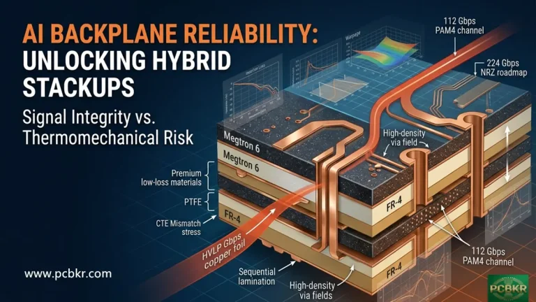
2. The CTE Mismatch Tax in Ultra-Thin Stack-Ups
Rigid-flex PCBs combine materials with fundamentally different coefficients of thermal expansion (CTE). FR-4 rigid sections have a CTE of approximately 14–17 ppm/°C in the XY plane, while polyimide flex sections run at 12–20 ppm/°C depending on orientation. At standard board thickness, the mechanical stiffness of the board suppresses differential expansion. At ultra-thin dimensions, this suppression is absent — differential expansion during lamination pressing and reflow soldering generates internal stress that directly reduces yield. Designing transition zone geometries with gradual stiffness changes (tapered rigid areas, strain-relief features) adds a small upfront DFM cost but meaningfully improves lamination yield, effectively paying for itself many times over in reduced scrap.
3. The Incremental Cost of Each “Specialty” Feature Compounds Non-Linearly
Individual premium features — blind vias, controlled impedance, ENIG, tight tolerances, non-rectangular outlines — each carry stated cost premiums of 10–50%. What is rarely articulated is that these premiums are multiplicative, not additive. A design with five specialty features, each carrying a 20% premium, does not cost 100% more — it costs approximately (1.2)⁵ = 149% more. For ultra-thin rigid-flex HDI designs where multiple specialty features are common, this compounding effect is a primary driver of “unexpectedly” high quotes. The practical implication: eliminating even one specialty feature from a heavily-loaded design can save disproportionately more than its stated individual premium suggests.
4. Adhesiveless Laminates: When the Premium Pays Back
Adhesiveless laminates cost 3–4× more than adhesive-based equivalents. Most cost guides recommend avoiding them unless required for high-reliability applications. However, in ultra-thin rigid-flex HDI designs specifically, adhesiveless laminates can reduce total stack-up thickness by 15–25 μm per layer (the thickness of the adhesive layer eliminated). This thickness reduction has downstream effects: it can eliminate the need for an additional prepreg ply to hit thickness targets, it reduces via aspect ratio (making drilling easier and cheaper), and it improves plated through-hole reliability (reducing yield losses). When these downstream benefits are factored into total system cost — especially for designs where one fewer prepreg ply can be used — adhesiveless construction can reach cost parity with adhesive-based at quantities above roughly 200 units.
5. The Volume-Quality Trade-Off for Ultra-Thin HDI: Don’t Over-Prototype
Standard advice recommends starting with small prototype runs and ramping up. For ultra-thin rigid-flex HDI, this advice needs modification. Because ultra-thin designs have inherently higher scrap rates, prototype-phase per-unit costs are amplified beyond the standard prototype premium. A small prototype run of 5 units at $420 per unit (6-layer HDI with stiffeners) means you are paying $420 per learning opportunity. Thorough simulation, mechanical flexure modeling, and DFM review before the first prototype run reduce the number of prototype iterations needed and directly lower total development cost — often more than simply ordering larger prototype batches.
Reference Cost Impact Table: Ultra-Thin Rigid-Flex HDI PCBs
| Cost Factor | Impact Level | Typical Premium | Optimization Approach |
|---|---|---|---|
| Layer count (flex layers) | Very High | 30–40% per added layer pair | Minimize flex layers; use rigid for structural thickness |
| No-flow prepreg usage | Very High | 10× vs. standard prepreg per ply | Reduce rigid-flex layer count; use rigid laminates for thickness |
| Laser drilling cycles | High | $70–90 per cycle | Optimize stack-up to minimize drilling events |
| Polyimide substrate grade | High | 2–10× vs. FR-4 | Match grade to actual temperature/performance requirement |
| Lamination cycles | High | 15–25% per added cycle | Eliminate buried vias where possible; consolidate layer builds |
| Panel utilization | High | 10–40% depending on efficiency | Design to standard panel dimensions; use rectangular outlines |
| Blind/buried vias | High | 25–50% over through-hole | Use through-holes; convert to through-hole where routing allows |
| Controlled impedance scope | Medium | 10–20% + test coupon area loss | List only impedances requiring production testing |
| Surface finish selection | Medium | +0% to +100% over OSP | Use immersion tin/silver instead of ENIG where possible |
| Copper weight | Medium | +10–80% vs. ½ oz baseline | Use lightest copper that meets current requirements per zone |
| Pouched flex arms | Medium | 15–30% | Terminate all flex arms in rigid sections |
| Rush lead time | Medium | 50–200% | Plan schedule for 2–3 week standard lead time |
| Ultra-thin handling risk | Medium | Embedded in yield losses | Consider slight thickness increase if marginally thin |
| Via-in-pad with fill | Medium | 20–35% | Use offset pads or micro-dogbone fanout |
| Soldermask color (non-green) | Low | 10–20% | Use standard green unless branding requires otherwise |
| Custom drill sizes | Low | $200–500 per unique size | Use fabricator’s standard tooling size library |
Conclusion
The Core Principle of Ultra-Thin Rigid-Flex HDI Cost Optimization
Cost optimization for ultra-thin rigid-flex HDI PCBs is not about finding a cheaper manufacturer or cutting corners on quality. It is about making informed, deliberate decisions at the design stage — before tooling is committed and before the design is frozen — about which features are genuinely required versus which reflect over-specification, design habit, or unexamined default settings.
The hierarchy of interventions, from highest to lowest leverage, is clear from the evidence:
- Layer count reduction is the single highest-impact design change available and should be the first analysis performed on any design.
- Stack-up architecture optimization — specifically minimizing laser drilling cycles and lamination events — can deliver 10–25% savings with no functional trade-off.
- Panel utilization improvement through outline rationalization is free in engineering terms and directly reduces per-unit material cost.
- Complexity elimination — removing specialty features that are not functionally mandatory, and recognizing that their combined compounding effect exceeds the sum of individual premiums.
- Material matching to actual requirements rather than to worst-case theoretical specifications.
- DFM engagement with your fabricator before design freeze, which consistently identifies savings unavailable through any other means.
For ultra-thin rigid-flex HDI designs specifically, the additional consideration of CTE mismatch management, carrier panel requirements, and the nuanced trade-off around adhesiveless laminates at volume must be factored in alongside the standard optimization levers documented in conventional rigid-flex and flex PCB guidance.
The engineering effort invested at the design phase — in simulation, DFM review, and stack-up analysis — has a return on investment that is difficult to match at any later stage of the product lifecycle. Cost optimization and design quality are not competing objectives in rigid-flex HDI design; they are achieved by the same discipline: precise, informed engineering decisions made as early as possible.
Still, need help? Contact Us: sales@pcbkr.com
Need a PCB or PCBA quote? Quote now
About Author
David Chen https://www.linkedin.com/in/pcbcoming/
David Chen boasts an extensive professional background in PCBA manufacturing, PCBA testing, and PCBA optimization, with specialized expertise in high-precision PCBA fault analysis and rigorous PCBA reliability testing. Skilled in complex circuit design and cutting-edge advanced PCB manufacturing processes, he delivers solutions that elevate product durability and performance across industrial applications. His technical articles focusing on PCBA manufacturing workflows and testing methodologies are widely cited by industry peers, research institutions, and technical platforms, solidifying his reputation as a recognized technical authority in the global circuit board manufacturing sector.