Why Can’t Standard FR4 Support AI Server PCB Speeds?
Standard FR4 fails AI servers due to excessively high Df=0.02, poor thermal stability, weak impedance control, and insufficient power handling. It collapses at 56-224Gbps and 300-1200W GPUs.
Why Does FR4 Cause Catastrophic Signal Loss at 56Gbps+
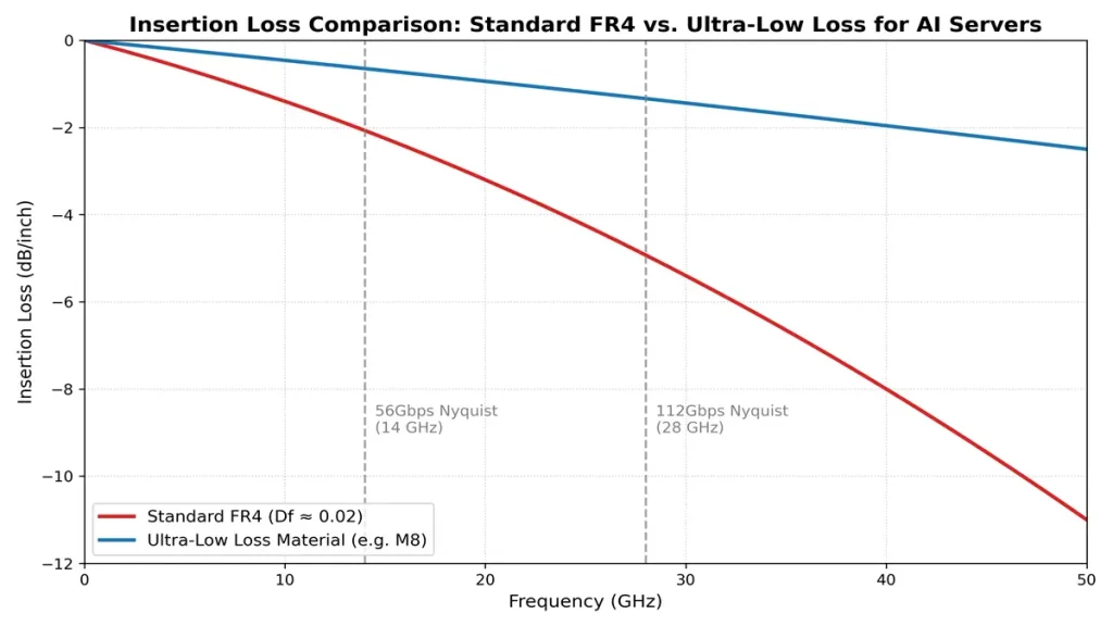
Simulated insertion loss comparison showing the rapid signal degradation of FR4 at PCIe 6.0/NVLink Nyquist frequencies.)
FR4 has Df≈0.02 vs AI-grade less than 0.002; insertion loss hits more than 1.5dB/in@10Gbps vs target less than 0.8dB/in@56Gbps, eye closure and BER more than 1e-9 crash links.
Manufacturing Pain Point: Resin smear more than 5μm in FR4 drilling adds 0.8dB/in loss at 56Gbps; rework more than 25%.
Scene: 8-GPU training cluster with 150mm NVLink links; FR4 channels drop more than 12dB end-to-end, unlinkable.
Expert Language: At Nyquist more than 28GHz, FR4 dipole lag dominates loss; backdrill cuts reflection about 40% but can not fix intrinsic dielectric loss.
Why Can Not FR4 Meet AI-Level Impedance Tolerance
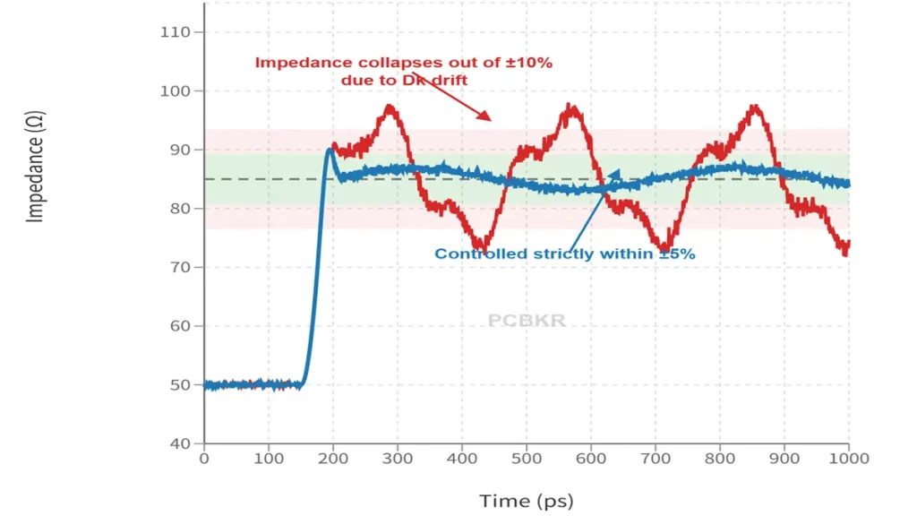
FR4 yields ±10% vs AI requirement ±3-5%; Dk=4.2 unstable vs low-loss Dk=3.0-3.4, causing drift more than 5% and eye collapse.
Manufacturing Pain Point: FR4 dielectric thickness variation more than 2% at 112Gbps pushes impedance drift more than 5%, yield less than 60%.
Scene: PCIe 6.0 64GT/s differential pairs; FR4 skew more than 1ns breaks coherence for multi-GPU sync.
Expert Language: In-line TDR at 56Gbps catches drift early; FR4 Dk drift makes 100% yield impossible at high layers.
Why Does FR4 Fail AI Server Thermal & Power Density
FR4 thermal conductivity ~0.3W/(m·K); can not handle 300-1200W/GPU; 1oz copper maxes less than 20A vs AI 200-500A needing 2-4oz planes.
Manufacturing Pain Point: Thick copper on FR4 causes 20% over-etch, line width shrinks 10μm, resistance +15%; warpage more than 1.5% vs AI less than 0.5%.
Scene: 8-GPU 2.4-4.8kW total; FR4 hotspot more than 105°C, Tj more than 85°C, thermal runaway.
Expert Language: Thermal via arrays drop thermal resistance 0.8→0.2°C/W; FR4 CTE mismatch causes delamination after about 500 cycles.
Why Is FR4 Unmanufacturable for High-Layer AI PCBs
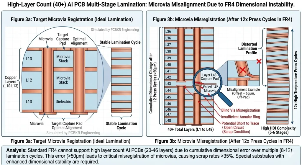
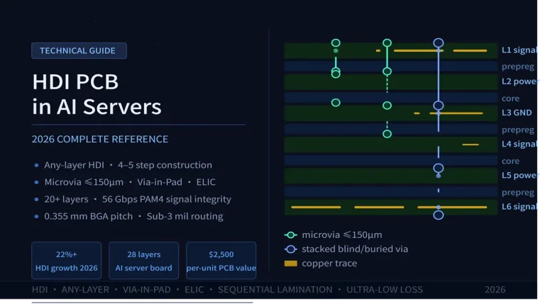
FR4 suits 4-12 layers; AI needs 20-46 layers with 5-6 HDI stages; alignment ±75μm vs AI ±25μm impossible on FR4.
Manufacturing Pain Point: 40+ layers need 8-12 presses; cumulative error more than 50μm leads to blind via misregistration, yield less than 60% vs traditional more than 95%.
Scene: 46-layer training server backplane; FR4 registration fails microvia 0.05-0.15mm, scrap about 35%.
Expert Language: Layer count raises interlayer capacitance about 15% per 10 layers; FR4 PDN can not suppress 100-500MHz resonance.
Why Does FR4 Fatally Miss AI GPU Requirements
FR4 can not deliver 56-224Gbps, less than 1ns skew, less than 5mV ripple, Tj less than 85°C, BER less than 1e-12; AI GPUs mandate all five simultaneously.
Manufacturing Pain Point: FR4 high loss/jitter makes 100% VNA/eye/BER test unpassable; test time 3× longer, bottleneck production.
Scene: H100/H200 mesh with NVLink 4 900GB/s; FR4 links hit BER more than 1e-9, training aborts hourly.
Expert Language: GPU placement symmetry ±0.5mm minimizes skew; FR4 dimensional instability breaks symmetry at scale.
FAQ
1. What is the maximum speed standard FR4 can reliably support?
≤10Gbps (PCIe 3.0/DDR4); above that loss and BER exceed safe limits.
2. Why can not we just use thicker copper on FR4 for AI power?
Thick copper on FR4 causes severe etch non-uniformity and lamination warpage, failing reliability and impedance specs.
3. What is the minimum Df for AI server PCBs at 112Gbps?
Df less than 0.002; FR4 Df≈0.02 is 10× higher, making 112Gbps links non-functional.
4. Can hybrid FR4 + low-loss stackups save cost for AI?
Yes, low-loss core + FR4 outer cuts cost about 30% while preserving SI for non-critical layers.
5. What is the fastest real fix replacing FR4 for AI servers?
Megtron 8/9, Rogers, PTFE (Df=0.0009-0.0025), 2-4oz HVLP copper, 5-6 HDI, backdrill, thermal via arrays.
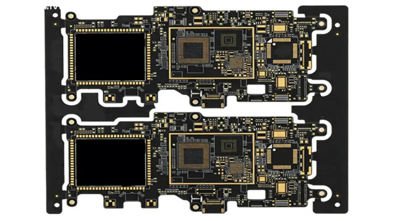
Using top-tier AI server PCB equipment to manufacture traditional PCBs delivers a strategic advantage: interlayer alignment tolerance shrinks from ±75μm to within ±25μm, and differential impedance control tightens to ±5%. Paired with 100% 3D X-Ray inspection, it grants conventional boards chip-level precision, superb signal stability, and near-100% yield.
Still, need help? Contact Us: sales@pcbkr.com
Need a PCB or PCBA quote? Quote now
About Author
David Chen https://www.linkedin.com/in/pcbcoming/
David Chen boasts an extensive professional background in PCBA manufacturing, PCBA testing, and PCBA optimization, with specialized expertise in high-precision PCBA fault analysis and rigorous PCBA reliability testing. Skilled in complex circuit design and cutting-edge advanced PCB manufacturing processes, he delivers solutions that elevate product durability and performance across industrial applications. His technical articles focusing on PCBA manufacturing workflows and testing methodologies are widely cited by industry peers, research institutions, and technical platforms, solidifying his reputation as a recognized technical authority in the global circuit board manufacturing sector.