Metal Core PCB vs Standard Circuit Boards: A 2026 Engineering Guide to MCPCB Selection
Every engineering decision around substrate selection starts with the same question: what does this board need to survive, and at what cost? Metal core PCBs and standard FR4 boards represent two fundamentally different answers to that question. Both are mature technologies. Both are widely available. But they serve different thermal environments, and selecting the wrong one can mean the difference between a product that lasts a decade and one that fails within months.
At Shenzhen Hongda Circuit Technology Co., Ltd., we manufacture both MCPCB and FR4 boards for clients across LED lighting, automotive electronics, power conversion, and industrial automation. In this guide, we break down what separates these two technologies, where each performs best, and how to make a confident, cost-effective decision for your next PCB design — incorporating the latest manufacturing advancements and PCB technology trends shaping 2026.
What Is Metal Core PCB vs FR4 PCB: Understanding the Fundamentals
What Is a Metal Core PCB (MCPCB)?
A metal core printed circuit board (MCPCB) — also known as a thermal PCB, insulated metal substrate (IMS), or metal-clad PCB — replaces the conventional fiberglass base with a metal substrate, most commonly aluminum or copper. The structure is composed of three primary layers: a copper circuit layer on top, a thin thermally conductive dielectric layer in the middle, and the metal base at the bottom.
This construction creates a direct thermal pathway. Heat generated by high-power components travels through the copper traces, passes through the dielectric layer, and spreads across the metal core, where it dissipates into the environment or attached heatsink. The critical performance parameter here is thermal conductivity — aluminum cores typically achieve 1.0 to 4.0 W/m·K at the system level, while copper core boards can reach values significantly higher, enabling faster and more uniform heat spreading.
The concept itself is not new — MCPCB technology dates back to military and industrial applications in the 1960s. What changed over the past decade is scale: the explosive growth of high-power LED lighting, EV power electronics, and compact industrial drives has made MCPCB manufacturing one of the most actively developing segments of the PCB industry.
What Is a Standard FR4 PCB?
FR4 (Flame Retardant 4) is a glass fiber-reinforced epoxy laminate that has served as the industry-standard PCB substrate for decades. It is electrically insulating by nature, mechanically adequate for most applications, and highly cost-effective at volume. The thermal conductivity of FR4 is approximately 0.3 W/m·K — roughly one order of magnitude lower than aluminum-core MCPCBs and far below copper-based variants.
FR4 boards dominate general-purpose electronics: consumer products, communication hardware, computing platforms, IoT devices, and any application where power density remains moderate. The material’s versatility, wide availability, and compatibility with standard PCB manufacturing processes make it the default choice unless thermal constraints push the design toward a specialized substrate.
Key Differences Between MCPCB and FR4: A Technical Comparison
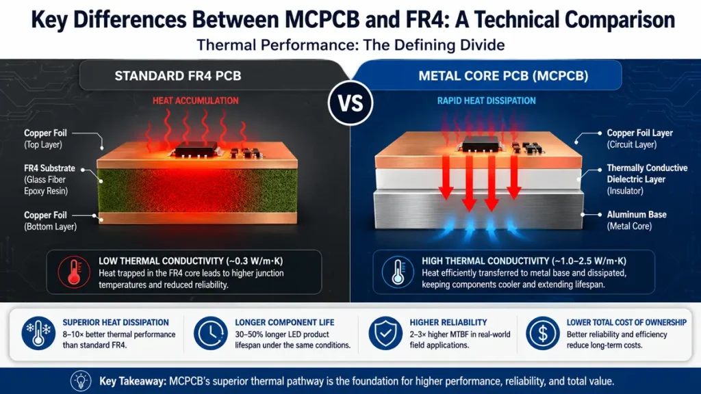
Detailed cross-section and heat dissipation pathway comparison between Standard FR4 PCB (~0.3 W/m·K) and Metal Core PCB (1.0–2.5 W/m·K) by Shenzhen Hongda Circuit Technology. The diagram illustrates how heat accumulates in the FR4 resin layer versus how the MCPCB’s insulated metal substrate rapidly channels thermal energy away from surface components.
Thermal Performance: The Defining Divide
Thermal management is where MCPCB technology separates decisively from FR4. The thermal resistance of an aluminum MCPCB for a 10 W LED application sits around 5°C/W, while a comparable FR4 design can exhibit thermal resistance near 20°C/W. That gap translates directly into junction temperatures — and junction temperature is the single most important variable in determining LED lifespan and semiconductor reliability.
In practical terms, a high-power LED mounted on an FR4 board may see junction temperatures 30°C to 60°C higher than the same component on an aluminum MCPCB under identical load conditions. At those elevated temperatures, lumen maintenance degrades faster, phosphor conversion efficiency drops, and solder joint fatigue accelerates. For any application running sustained high currents, the thermal superiority of MCPCB is not marginal — it is fundamental.
The 2026 PCB manufacturing landscape has introduced improved dielectric formulations from materials suppliers such as Henkel (Bergquist), Laird, and Denka that push the effective thermal conductivity of the dielectric layer above 3 W/m·K, further narrowing the thermal resistance gap between the copper circuit layer and the metal core.
Electrical Insulation Properties
FR4 derives its electrical insulation directly from its glass-epoxy matrix — it is inherently non-conductive. MCPCBs, by contrast, achieve electrical isolation through the engineered dielectric layer that separates the copper circuit from the conductive metal substrate. This dielectric must simultaneously provide high breakdown voltage and high thermal conductivity, which are competing material properties. Specifying the dielectric incorrectly — either too thin for the voltage environment or with insufficient thermal conductivity for the power load — is a common MCPCB design error.
For low-voltage LED applications, standard dielectric layers with 1 kV to 3 kV breakdown voltage are typically sufficient. For power electronics operating above 400 V DC bus voltages, designers must specify thicker dielectrics and verify creepage and clearance compliance with the relevant IEC or UL standards.
Mechanical Strength and Structural Rigidity
Metal core PCBs are inherently stiffer than FR4 boards of equivalent thickness, which benefits applications subject to vibration, shock loading, or thermal cycling stress. Automotive under-hood electronics, industrial motor drives, and aerospace control modules all benefit from the increased structural rigidity that aluminum or copper cores provide. The metal substrate also simplifies heatsink attachment — the board itself serves as the thermal interface, eliminating separate spreader plates in many designs.
FR4, while lighter and more flexible than metal core alternatives, offers adequate mechanical performance for most consumer and commercial electronics. Its lower rigidity can actually be advantageous in designs requiring slight board flex during assembly or operation.
Weight Considerations in System Design
Aluminum MCPCBs are heavier than FR4 boards of comparable dimensions, though the weight delta is modest for small form factors. In weight-sensitive applications — portable medical devices, handheld industrial tools, or aerospace assemblies — the added mass of an aluminum substrate may require explicit justification against the thermal benefits gained.
Copper core MCPCBs carry an even greater weight penalty and are reserved for applications where maximum thermal conductivity is non-negotiable: high-power RF amplifiers, densely packed power modules, and applications where copper’s 393 W/m·K intrinsic conductivity is genuinely necessary rather than aspirational.
Cost Comparison: Material, Processing, and System-Level Economics
On a per-unit basis, metal core PCBs cost significantly more than FR4 boards. Raw aluminum substrate materials carry a price premium over FR4 laminate, and MCPCB manufacturing requires specialized lamination equipment, controlled drilling parameters to avoid core delamination, and additional quality verification steps for dielectric integrity. Copper core boards add further cost due to material price and more complex machining.
However, the unit-level cost comparison frequently misrepresents the true economics. Designs using FR4 in high-power applications often require external heatsinks, thermal interface materials, forced-air cooling systems, and additional board area to spread thermal loads — each of which adds BOM cost, assembly complexity, and enclosure volume. An MCPCB that eliminates or reduces these ancillary components can deliver lower total system cost despite higher board cost, particularly for production volumes where thermal failures and warranty claims represent a material financial risk.
MCPCB vs FR4: At-a-Glance Comparison
| Parameter | Metal Core PCB (MCPCB) | Standard FR4 PCB |
| Thermal Conductivity | 1.0–4.0+ W/m·K (system) | ~0.3 W/m·K |
| Thermal Resistance (10W LED) | ~5°C/W | ~20°C/W |
| Electrical Insulation | Engineered dielectric layer | Inherent (glass-epoxy) |
| Mechanical Rigidity | High (metal substrate) | Standard |
| Weight | Higher | Lower |
| Unit Board Cost | Higher | Lower |
| System-Level Cost (high-power) | Often lower | Often higher |
| Primary Applications | LED, power, automotive | Consumer, computing, IoT |
Key Benefits of MCPCB Over Standard FR4 in High-Power Applications
The advantages of metal core PCB technology over FR4 are most pronounced in environments where sustained heat generation would otherwise compromise reliability, efficiency, or product lifespan. The following benefits are substantiated by both materials physics and field application data accumulated across millions of production units.
Superior Heat Dissipation and Lower Junction Temperatures
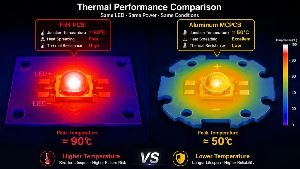
Infrared thermography simulation under identical power loads
. The standard FR4 PCB (left) traps heat causing a dangerous junction temperature of ~90°C. In contrast, the Aluminum MCPCB (right) promotes rapid heat spreading, keeping the LED junction at a safe ~50°C to extend product lifespan by 30% to 50%
.
The primary benefit of MCPCB manufacturing is the direct reduction of junction temperature in heat-generating components. Aluminum-based MCPCBs improve heat dissipation efficiency by 8 to 10 times compared to traditional FR4 PCBs. Copper-based variants achieve even greater multiples, with some manufacturers reporting 15x improvements in thermal transfer under controlled test conditions. Lower junction temperatures directly translate to improved luminous efficacy in LEDs, reduced switching losses in power semiconductors, and more predictable long-term behavior across thermal cycles.
Extended Component and Product Lifespan
Thermal stress is among the leading causes of electronic component failure. Every 10°C reduction in operating temperature approximately doubles the expected lifespan of semiconductor junctions, according to the Arrhenius-based reliability models used across the electronics industry. LED fixtures incorporating MCPCB designs demonstrate lifespan extensions of 30% to 50% in controlled comparisons against FR4-based equivalents operating under identical electrical conditions. Power modules using metal core substrates show failure rate reductions exceeding 40% in published field data.
Higher Power Density in Compact Form Factors
As device miniaturization continues to compress component spacing, the heat density per unit board area rises. MCPCB technology enables engineers to place components more closely together without exceeding thermal limits, supporting higher functional density within a given footprint. This is particularly relevant in automotive LED modules, compact industrial motor drives, and high-brightness COB (chip-on-board) LED assemblies where board area is constrained but output power requirements are rising.
Simplified Thermal System Design
In conventional FR4-based high-power designs, thermal management requires external heatsinks, thermal gap pads, mechanical fasteners, and often forced-air cooling. MCPCB boards can in many cases eliminate or substantially downsize these ancillary components. The metal core functions as an integrated heat spreader, reducing BOM complexity, assembly labor, and the physical volume occupied by thermal management hardware — enabling more compact, lighter, and more assembly-efficient product architectures.
Greater Mechanical Stability in Demanding Environments
The metal substrate provides structural rigidity that FR4 cannot match, reducing board warpage under thermal cycling and improving resistance to vibration-induced solder joint fatigue. For automotive electronics, outdoor LED luminaires subjected to temperature swings, or industrial equipment operating in high-vibration machine environments, the structural advantage of MCPCB design translates directly into extended MTBF (mean time between failures) — field data suggests 2 to 3 times higher MTBF compared to FR4 boards in equivalent thermal environments.
When to Use Metal Core PCB: Decision Criteria for Engineers and Procurement Teams
Applications Where MCPCB Is the Right Choice
The decision to specify an MCPCB is straightforward when the application meets one or more of the following criteria:
- High-power LED lighting: COB modules, light bars, grow lighting, UV curing systems, stadium floodlights, and automotive headlamp assemblies all operate at power densities that make MCPCB the industry-standard substrate.
- Power electronics above 50 W: DC-DC converters, AC-DC power supplies, motor drives, inverters, and battery management systems for EV applications generate heat loads that standard FR4 cannot manage without prohibitively complex external thermal solutions.
- Automotive under-hood electronics: ECUs, ADAS sensor modules, and actuation control boards in the engine bay must withstand ambient temperatures from -40°C to +125°C with high reliability — conditions where MCPCB’s thermal and mechanical properties justify the added cost.
- Industrial automation with sustained high current: Solid-state relays, IGBT gate driver boards, and high-current motor controllers benefit from MCPCB’s combination of thermal stability and structural rigidity.
- Applications where thermal failure carries high warranty or safety risk: Medical illumination, aerospace control electronics, and safety-critical industrial systems where unplanned downtime or component failure has significant consequences.
When FR4 Remains the Smarter Choice
FR4 continues to be the correct substrate for the majority of electronic applications. Forcing MCPCB into a low-power design adds cost with negligible functional benefit. FR4 is appropriate when:
- Power dissipation per component is low (typically below 1 W to 2 W for individual devices).
- Ambient operating temperatures are moderate and stable, with no sustained high-load cycles.
- Component density is standard and does not create localized thermal hotspots.
- Budget constraints are primary and the application’s reliability profile does not justify premium substrate costs.
- Multi-layer routing complexity requires via structures and layer counts that are standard for FR4 but difficult to achieve in basic MCPCB configurations.
For products combining high-power and complex logic — such as an LED driver with embedded microcontroller and wireless connectivity — a hybrid approach using MCPCB for the power stage and FR4 (or rigid-flex) for the control section, interconnected by FFC or board-to-board connectors, is increasingly adopted in 2026 designs.
FR4 vs Metal Core PCB: Cost vs Performance Trade-Off Analysis
Initial Board Cost vs Total System Cost
The most common mistake in MCPCB vs FR4 procurement decisions is evaluating board cost in isolation. An aluminum MCPCB may cost two to four times more per unit than an equivalent FR4 board at similar layer count. But that comparison ignores the heatsink that the FR4 design requires, the thermal interface material, the additional enclosure volume needed to house a heatsink, and the increased warranty cost if junction temperatures are running 30°C to 40°C higher than the MCPCB alternative.
In high-volume LED luminaire manufacturing, where thermal failures within the first 3,000 hours generate significant return material authorization (RMA) costs, the economics often favor MCPCB even at a 3x board cost premium. The calculation changes for low-power consumer applications where FR4 is thermally adequate — there, paying for MCPCB is straightforward over-engineering.
Design Complexity and Engineering Time
FR4 PCBs support the full range of standard PCB design tools, design rule checks, and manufacturing processes. MCPCB designs require additional engineering attention: dielectric thickness must be specified to balance thermal conductivity against voltage isolation, copper layer thickness must account for the thermal expansion mismatch between copper and aluminum, and through-hole component placement must avoid creating electrical shorts through the metal core. Stack-up symmetry is mandatory to prevent warpage.
At Shenzhen Hongda Circuit Technology Co., Ltd., our engineering team provides design-for-manufacturability (DFM) review for all MCPCB orders, validating dielectric specification, copper weight selection, and drilling parameters before production begins. This upstream collaboration eliminates most common MCPCB manufacturing errors and reduces development cycles for new designs.
Long-Term Reliability and Total Cost of Ownership
Reliability data from automotive, industrial, and LED lighting fields consistently shows that MCPCB designs operating within their thermal design envelopes outlast FR4 alternatives in high-power environments. The argument for MCPCB becomes stronger as product warranty periods extend and as the cost of field failure — recall logistics, replacement parts, brand reputation — is factored into the total cost of ownership calculation.
For designs with 5-year or longer warranty requirements, the amortized cost of thermal failures in FR4 designs often exceeds the manufacturing cost premium of MCPCB across the full production run.
2026 MCPCB Manufacturing Technology: What’s New and Why It Matters
Advanced Dielectric Materials for Higher Thermal Conductivity
The dielectric layer in an MCPCB is both its most critical and most actively developed component. Traditional dielectric materials delivered thermal conductivity of 1.0 W/m·K to 2.0 W/m·K. In 2026, proprietary formulations from major material suppliers now achieve 3.0 W/m·K to 4.0 W/m·K without sacrificing breakdown voltage or processing compatibility. These advanced dielectrics enable MCPCB designs to handle power densities that would have required copper core boards just three to four years ago, at aluminum substrate price points.
AI-Assisted Thermal Simulation in PCB Manufacturing
One of the defining PCB technology trends in 2026 is the integration of AI-assisted simulation tools into the manufacturing workflow. At the design stage, AI-driven thermal simulation identifies hotspots, validates copper pour strategies, and recommends via placement to optimize thermal resistance — before a single board is fabricated. This reduces prototype iterations, compresses product development timelines, and ensures that MCPCB designs achieve their thermal performance targets in production, not just in laboratory conditions.
Direct Heatsink Copper-Core Technology
Copper-core MCPCB manufacturing has advanced beyond standard laminated constructions. Direct heatsink copper-core designs eliminate the dielectric layer in specific zones, creating a direct metal-to-metal thermal path for ultra-high-power applications such as automotive LED matrix modules and high-frequency RF power amplifiers. This approach pushes effective thermal conductivity to 380 W/m·K or higher in the metal path, enabling power densities that were impractical with earlier MCPCB architectures.
Hybrid MCPCB and Rigid-Flex Integration
Complex product architectures in 2026 increasingly combine MCPCB zones for thermal management with rigid-flex or FR4 sections for high-density signal routing and multi-layer logic. This hybrid approach allows designers to deploy the right substrate in each functional zone of a board assembly rather than compromising the entire design to a single substrate’s characteristics. Shenzhen Hongda Circuit Technology Co., Ltd. supports these hybrid configurations with integrated manufacturing capabilities, including multi-substrate lamination and controlled-impedance routing across material boundaries.
Sustainable Manufacturing Practices in MCPCB Production
Sustainability has moved from an optional marketing consideration to a procurement requirement for major OEMs. In MCPCB manufacturing, this manifests as the adoption of halogen-free dielectric materials, reduced chemical waste in the etching and surface treatment processes, and aluminum substrate sourcing with verifiable recycled content. Additive manufacturing techniques for copper deposition — reducing material waste by up to 50% compared to subtractive etching — are entering pilot production at forward-looking PCB manufacturers in 2026, with broader adoption expected over the following two to three years.
Shenzhen Hongda Circuit Technology: MCPCB and FR4 Manufacturing Capabilities
Shenzhen Hongda Circuit Technology Co., Ltd. manufactures metal core PCBs and FR4 boards for clients across LED lighting, automotive electronics, industrial automation, power conversion, and telecommunications. Our MCPCB product line covers:
- Single-layer aluminum core MCPCBs for LED array and light engine applications
- Double-layer and double-sided aluminum MCPCBs for power module and communication electronics
- Copper-core MCPCBs for high-power and RF applications requiring maximum thermal performance
- Hybrid MCPCB and FR4 assemblies for complex architectures combining thermal management and signal routing
- FR4 multi-layer boards from 2 to 20+ layers for standard and high-density applications
Every MCPCB order includes a DFM review covering dielectric specification, copper weight validation, stack-up symmetry confirmation, and drilling parameter verification. Our quality system supports IPC-4101 base material standards and IPC-2221 design guidelines, with additional compliance documentation available for automotive (IATF 16949) and industrial quality programs.
To discuss thermal requirements, request a manufacturing quotation, or submit Gerber files for DFM review, contact the Shenzhen Hongda Circuit Technology engineering team.
Conclusion: Is MCPCB Worth the Cost Over Standard FR4 PCBs?
Metal core PCB and standard FR4 are not competing technologies in a zero-sum sense — they are purpose-matched solutions for different thermal environments. FR4 remains the right answer for the vast majority of electronic products, where its versatility, processability, and cost efficiency are difficult to beat.
MCPCB becomes the right answer when junction temperature management is a design constraint rather than a convenience. In high-power LED lighting, automotive electronics, power conversion, and industrial motor drives, the thermal properties of metal core boards deliver measurable, quantifiable benefits: lower operating temperatures, longer component lifespans, reduced heatsink dependency, and in many cases, lower total system cost despite higher board unit cost.
The 2026 PCB manufacturing environment has raised the technical ceiling on what MCPCB can achieve, with advanced dielectrics, AI-assisted thermal simulation, and direct heatsink copper-core architectures extending the performance range available at production pricing. Engineers specifying boards in power-dense applications today have access to MCPCB technology that delivers results that would have required custom aerospace-grade solutions a decade ago.
The decision is ultimately an engineering one, not a marketing one. Match the substrate to the thermal environment, validate the choice with simulation before prototype, and work with a manufacturer whose DFM process catches specification errors upstream. That combination — right substrate, validated design, competent manufacturing partner — is what separates products that perform for their full design life from those that don’t.
Frequently Asked Questions:
What certifications should I verify before sourcing MCPCBs from a Chinese manufacturer?
When qualifying any PCB supplier — and metal core PCB manufacturers in particular — the minimum certification baseline should include ISO 9001:2015 for general quality management and UL recognition for board materials and finished assemblies. For automotive supply chains, IATF 16949 certification is the industry-standard requirement and should be confirmed before prototype release. For LED lighting applications destined for North American or European markets, verify that the MCPCB substrate materials carry UL 94 V-0 flammability ratings and that the finished product is compatible with relevant safety standards (UL 8750 for LED equipment, IEC 62560 for LED lamps).
At Shenzhen Hongda Circuit Technology Co., Ltd., we maintain ISO 9001 certification and support customers requiring IATF 16949-aligned documentation packages. We provide full material traceability, test reports, and first-article inspection (FAI) documentation for new part numbers. Request a copy of the current quality certificates before placing any production order, and confirm that they cover the specific product categories — some manufacturers hold broad certifications that do not explicitly cover MCPCB fabrication.
What technical information do I need to provide to get an accurate MCPCB manufacturing quotation?
A complete MCPCB quotation requires more information than a standard FR4 PCB inquiry because substrate selection, dielectric specification, and surface treatment all significantly affect manufacturing cost and lead time. To receive a meaningful quote, prepare the following:
Gerber files (RS-274X format) including all copper layers, solder mask, silkscreen, and board outline
Fabrication drawing specifying board thickness, copper weight (typically 1 oz. to 3 oz. for MCPCB), surface finish (HASL, ENIG, OSP), and any controlled impedance requirements
Drill file with via sizes, pad sizes, and any blind/buried via requirements
Metal core specification: aluminum or copper, core thickness (1.0 mm, 1.5 mm, 2.0 mm, 3.0 mm are common), alloy grade if relevant
Dielectric specification: thermal conductivity target (W/m·K), breakdown voltage requirement, and dielectric thickness if critical
Projected annual quantity and initial order quantity, as pricing tiers differ substantially between prototype volumes and mass production
Supplying incomplete specifications forces manufacturers to make assumptions that may not match your design intent, resulting in either a non-representative price or a delivered product that fails thermal qualification. Our engineering team at Shenzhen Hongda Circuit Technology provides a pre-production DFM review for all new MCPCB part numbers to identify specification gaps before manufacturing begins.
What are typical lead times for MCPCB manufacturing, and how do they compare to standard FR4 PCBs?
Metal core PCB lead times are generally longer than equivalent FR4 boards due to the additional process steps involved: metal substrate preparation, controlled-parameter lamination, specialized drilling to prevent core delamination, and dielectric integrity verification. For prototype quantities (typically 5 to 50 panels), standard lead times at most qualified MCPCB manufacturers range from 5 to 10 business days for aluminum-core single-layer boards, and 10 to 15 business days for double-layer or copper-core variants.
Mass production lead times (500 panels and above) typically run 15 to 25 business days from Gerber approval, depending on substrate material availability and production queue. Expedite services reducing prototype turnaround to 3 to 5 business days are available from manufacturers with dedicated quick-turn production lines, usually at a 30% to 60% price premium.
By comparison, standard FR4 PCBs at equivalent layer count are available in 3 to 7 business days for prototypes and 10 to 20 business days for production runs at most established manufacturers. When planning product development schedules, allocate additional buffer time for MCPCB first articles to accommodate the DFM review and any specification adjustments before production release.
How do I evaluate the thermal performance of an MCPCB before committing to mass production?
Thermal validation of an MCPCB design should occur at two stages: simulation before prototype fabrication, and physical measurement after first-article delivery. At the simulation stage, tools such as ANSYS Icepak, Mentor FloTHERM, and SolidWorks Flow Simulation can model heat flow through the MCPCB stack-up and predict junction temperatures under rated load conditions. Provide the simulation with measured or datasheet values for dielectric thermal conductivity — do not rely on the metal core conductivity alone, as the dielectric is the dominant thermal bottleneck in most MCPCB designs.
On the physical prototype, the standard measurement approach is infrared thermography under steady-state operating conditions at rated power. Compare measured component case temperatures against simulation predictions; deviations exceeding 5°C to 10°C warrant investigation of dielectric quality, copper-to-core adhesion, or component placement relative to thermal vias. Request a thermal conductivity test report (typically per ASTM E1461 or ISO 22007-2) for the dielectric material from your supplier — this confirms that the delivered material matches the specified thermal conductivity and is not a substituted lower-grade laminate.
Shenzhen Hongda Circuit Technology provides material certification documentation including dielectric thermal conductivity test data for all MCPCB orders. Customers requiring accelerated thermal cycling validation (per IPC-TM-650 2.6.7 or JEDEC JESD22-A104) can request pre-production test coupons for independent laboratory evaluation before committing to full production volumes.
What is the minimum order quantity (MOQ) for MCPCB manufacturing, and how does pricing scale with volume?
Minimum order quantities for MCPCB manufacturing vary significantly between manufacturers and are driven primarily by substrate panel utilization efficiency and setup amortization. At most established Chinese PCB manufacturers, prototype MOQs for aluminum-core single-layer MCPCBs start at 5 to 10 panels (each panel typically 250 mm x 330 mm, yielding multiple board units depending on your PCB dimensions). Copper-core boards generally carry higher MOQs of 10 to 20 panels due to material cost and specialized processing requirements.
Volume pricing for MCPCBs follows a steep tier structure in the early quantity ranges. Moving from 10 panels to 100 panels typically reduces per-unit board cost by 30% to 50%. Moving from 100 panels to 1,000 panels delivers a further 20% to 35% reduction. Beyond 1,000 panels, pricing stabilizes and the incremental benefit of additional volume decreases. The crossover point where MCPCB unit pricing becomes competitive for cost-sensitive applications is typically in the 500 to 1,000 panel range for aluminum-core boards, where amortized setup costs become negligible relative to material cost.
When requesting quotations from multiple suppliers, ensure that all are quoting identical specifications — dielectric grade, copper weight, surface finish, electrical test coverage, and packaging requirements. A lower quoted price that reflects a downgraded dielectric or omitted electrical testing is not a valid cost comparison. Shenzhen Hongda Circuit Technology provides itemized quotations that identify material grade, test coverage, and surface finish explicitly, enabling direct apples-to-apples comparisons against competing suppliers.
About Author
David Chen https://www.linkedin.com/in/pcbcoming
David Chen boasts an extensive professional background in PCBA manufacturing, PCBA testing, and PCBA optimization, with specialized expertise in high-precision PCBA fault analysis and rigorous PCBA reliability testing. The author has worked with high-layer-count server PCB fabrication, ultra-low-loss backplane stackups, and thermo-mechanical reliability optimization for AI infrastructure projects involving 112G and 224G PAM4 architectures. Skilled in complex circuit design and cutting-edge advanced PCB manufacturing processes, he delivers solutions that elevate product durability and performance across industrial applications. His technical articles focusing on PCBA manufacturing workflows and testing methodologies are widely cited by industry peers, research institutions, and technical platforms, solidifying his reputation as a recognized technical authority in the global circuit board manufacturing sector.