High-Thermal Conductivity Aluminum PCB for LED andAutomotive Lighting: 2026 Manufacturing Technology Guide
Aluminum PCB for LED (also written as aluminium PCB for LED depending on regional spelling conventions) has emerged as the default substrate rather than an optional alternative, addressing the most critical bottleneck in modern high-power LED design. Thermal management is the single biggest constraint standing between a high-power LED design and its rated lifetime. As LED packages push past 3W, 5W, and 10W per die, junction temperature — not electrical design — becomes the limiting factor for lumen output, color stability, and mean time to failure. For automotive lighting engineers, the problem is compounded by vibration, humidity, and a temperature range that regularly exceeds 105°C under the hood or behind a sealed headlamp housing.
At Shenzhen Hongda Circuit Technology Co., Ltd., we manufacture high thermal conductivity aluminum PCB boards specifically for LED lighting and automotive lighting applications. This guide walks through the product structure, the manufacturing advances shaping 2026 production standards, and the practical selection criteria that procurement and engineering teams adopt when qualifying professional suppliers of aluminum PCB for LED solutions.
What Is an Aluminum PCB?
An aluminum PCB (sometimes called an aluminum circuit board, aluminum base PCB, or
metal core PCB / MCPCB) is a circuit board built on a metal substrate instead of standard
FR-4 fiberglass. The aluminum core does three jobs at once: it conducts electricity through
the copper traces on top, it pulls heat away from the components mounted on the board,
and it provides the mechanical rigidity that lets a thinner, lighter board survive vibration
and mounting stress.
Aluminum PCB Board Structure: Copper Layer, Dielectric Layer, Substrate
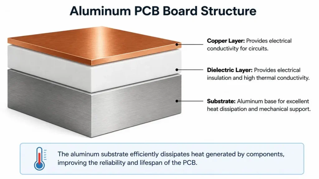
Standard Three-Layer Cross-Section Structure of an Aluminum PCB
A standard aluminum PCB board is built in three layers:
1. Circuit layer — copper foil, typically 1oz to 4oz depending on current density
requirements
2. Thermal dielectric layer — a resin system (often referred to as PP prepreg) filled with
ceramic particles to conduct heat while remaining an electrical insulator
3. Aluminum substrate — the base metal, most commonly 5052 or 6061 aluminum alloy, which spreads and dissipates heat to a heatsink or housing The dielectric layer is the part most engineers underestimate. It is the only layer standing between the copper trace and the metal base, so its thermal conductivity and dielectric withstand voltage determine how efficiently heat actually reaches the aluminum — and how safely the board handles the LED driver’s voltage.
How Aluminum PCB Manufacturing Has Moved Forward Going Into 2026
Aluminum PCB fabrication has not changed conceptually in over a decade, but the materials and process control behind it have. A few developments are now standard on modern production lines rather than premium options.
Higher-Performance Thermal Dielectric Materials
Newer ceramic-filled PP prepreg formulations push thermal conductivity from the older
1.0–1.5 W/m·K range into 2.0–3.0 W/m·K and above, without sacrificing dielectric breakdown
voltage. For a high-power LED driver board, this single material change can lower junction
temperature by several degrees without touching the layout.
Thermal Via and Copper Weight Precision
Modern laser drilling and plating control allow tighter thermal via arrays directly under
LED footprints, combined with heavier copper (2oz–4oz) in high-current automotive
circuits. The result is a shorter, lower-resistance thermal path from the LED die to the
aluminum base, and lower voltage drop across long traces feeding headlamp or taillight
modules.
Laser Direct Imaging and Automated Optical Inspection
Laser direct imaging (LDI) has replaced film-based exposure on most aluminum circuit
board lines, tightening trace and pad tolerances that matter for fine-pitch LED packages.
Paired with automated optical inspection (AOI) at multiple stages, this reduces the defect
escape rate that used to require manual rework on aluminum PCB manufacturer lines.
Surface Finish Options Matched to Application
ENIG (electroless nickel immersion gold) has become the default finish for automotive
grade aluminum PCB boards because of its flat surface and long shelf life, while HASL
remains common for cost-sensitive general LED lighting. Choosing the right finish is now
treated as part of the thermal and reliability design, not just a cosmetic step.
Aluminum PCB vs FR-4 Plus Heat Sink vs Copper Core PCB
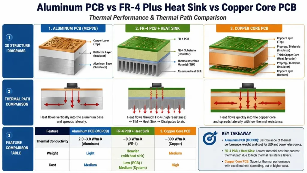
Thermal Performance and Heat Dissipation Path Comparison between Aluminum PCB (MCPCB), FR-4 with Heat Sink, and Copper Core PCB
Engineers evaluating a substrate for a new LED or automotive lighting design typically
compare three approaches:
| Approach | Thermal Resistance | Weight | Cost | Assembly Complexity |
|---|---|---|---|---|
| FR-4 + external heatsink | Higher — heat must cross an interface layer | Heaviest | Lower board cost, higher assembly cost | More parts, more assembly steps |
| Aluminum PCB (high thermal conductivity) | Low — heat path built into the board | Light | Moderate | Simpler, fewer external parts |
| Copper core PCB | Lowest | Heaviest of the three | Highest | Simpler, but costly |
An aluminum PCB sits in the middle: it delivers most of the thermal benefit of a copper core
board at a fraction of the weight and cost, while removing the external heatsink and its assembly steps entirely. This is why it has become the default choice for LED aluminum PCB and automotive LED PCB designs rather than a budget compromise.
Designing Aluminum PCB for LED and Automotive Lighting
Pad and Thermal Via Layout for High-Power LED Packages
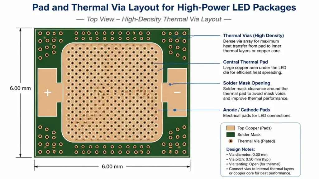
Recommended Pad Design and High-Density Thermal Via Layout for High-Power LED Packages
LED thermal pads need dense via arrays directly beneath the package, sized and filled to
match the LED manufacturer’s thermal datasheet. Getting via diameter, pitch, and plating
right is what separates a board that meets its rated lumen maintenance from one that
doesn’t.
Copper Thickness and Trace Strategy for Automotive Circuits
Automotive lighting circuits — headlights, taillights, daytime running lights, turn signals —
often carry higher sustained current than general LED lighting. Heavier copper weight and
wider trace geometry reduce both temperature rise and voltage drop, which matters over
the vehicle’s full operating temperature range.
Reliability Design for the Automotive Environment
Automotive PCB design also has to account for thermal cycling, vibration, and humidity
over the vehicle’s service life. This means the dielectric layer needs to hold its thermal and
dielectric performance through repeated hot-cold cycles, not just at a single test
temperature.
Case Studies: Aluminum PCB in LED and Automotive Lighting
High-power LED lighting module. A module originally built on FR-4 with an external
aluminum heatsink was running hot enough to cause visible lumen depreciation over its
rated life. Switching to a high thermal conductivity aluminum PCB, with an optimized via
array and heavier copper under the LED pads, brought junction temperature down
measurably, removed the need for the external heatsink, and reduced the module’s overall
footprint.
Automotive headlight LED module. A front headlamp design was constrained by housing
space and needed to meet automotive temperature cycling requirements with a lower
thermal resistance than the existing FR-4 layout allowed. Moving to an aluminum PCB with
an upgraded dielectric layer and revised board layout brought the design within its thermal
budget without adding an external heat spreader, while also simplifying assembly.
How to Choose an Aluminum PCB Manufacturer
Procurement and engineering teams evaluating an aluminum PCB manufacturer generally
look at:
1. Dielectric thermal conductivity — confirm the actual W/m·K rating of the prepreg
used, not just the substrate’s alloy
2. Dielectric withstand voltage — matched to the LED driver’s operating voltage and
any automotive isolation requirements
3. Copper weight and trace tolerance — appropriate to the current density and fine
pitch LED footprints in the design
4. Surface finish — ENIG for automotive-grade reliability, HASL where cost is the
priority
5.Process control — LDI imaging and multi-stage AOI as a baseline, not an upsell
Why Engineering Teams Work With Shenzhen Hongda Circuit Technology
Shenzhen Hongda Circuit Technology Co., Ltd. manufactures aluminum PCB boards built
specifically around the thermal and reliability requirements of LED lighting and automotive lighting programs — from prototype through mass production. Our engineering team works directly with customers on thermal via layout, copper thickness selection, and dielectric material choice before the design is locked, which is typically where thermal performance is won or lost. For teams comparing an aluminum PCB manufacturer against a copper core or FR-4-plus-heatsink alternative, we can quote and prototype all three so the trade-off is based on actual test data rather than a datasheet estimate.
Frequently Asked Questions
What is an aluminum PCB used for?
Aluminum PCBs are used anywhere heat generated by components — most commonly high-power LEDs, power converters, and motor drivers
— needs to be conducted away from the circuit efficiently. LED lighting and automotive lighting are two of the largest application areas because both involve high power density in a compact space.
How is an aluminum PCB made?
It is built by laminating a copper foil circuit layer to an aluminum substrate through a thermally conductive dielectric layer, then processing it through drilling, plating, imaging, etching, solder mask, and surface finish steps similar to a standard PCB, with added process control around the dielectric bond and thermal via formation.
How do I choose between an aluminum PCB manufacturer and a copper core PCB supplier?
? If the design’s thermal load can be met with 2.0–3.0 W/m·K dielectric
performance, an aluminum PCB manufacturer will typically deliver a lighter, lower-cost board than copper core. Copper core is worth the added cost and weight only when the thermal load genuinely exceeds what a well designed aluminum PCB can handle.
What certifications or qualifications should an automotive-grade aluminum PCB supplier have?
Look for IATF 16949 or equivalent automotive quality system certification,
UL-recognized base materials, and documented thermal cycling and reliability test data, in addition to standard IPC Class 2 or Class 3 board qualification depending on the program.
Can an aluminum PCB manufacturer support both prototype and mass production for a new LED lighting design?
Yes. A manufacturer working across both stages can carry the same dielectric material, via design, and copper specification from prototype through volume production, which avoids the thermal performance drift that can happen when prototype and mass-production boards are sourced from different suppliers or built to different specs
About Author
David Chen https://www.linkedin.com/in/pcbcoming
David Chen boasts an extensive professional background in PCBA manufacturing, PCBA testing, and PCBA optimization, with specialized expertise in high-precision PCBA fault analysis and rigorous PCBA reliability testing. The author has worked with high-layer-count server PCB fabrication, ultra-low-loss backplane stackups, and thermo-mechanical reliability optimization for AI infrastructure projects involving 112G and 224G PAM4 architectures. Skilled in complex circuit design and cutting-edge advanced PCB manufacturing processes, he delivers solutions that elevate product durability and performance across industrial applications. His technical articles focusing on PCBA manufacturing workflows and testing methodologies are widely cited by industry peers, research institutions, and technical platforms, solidifying his reputation as a recognized technical authority in the global circuit board manufacturing sector.