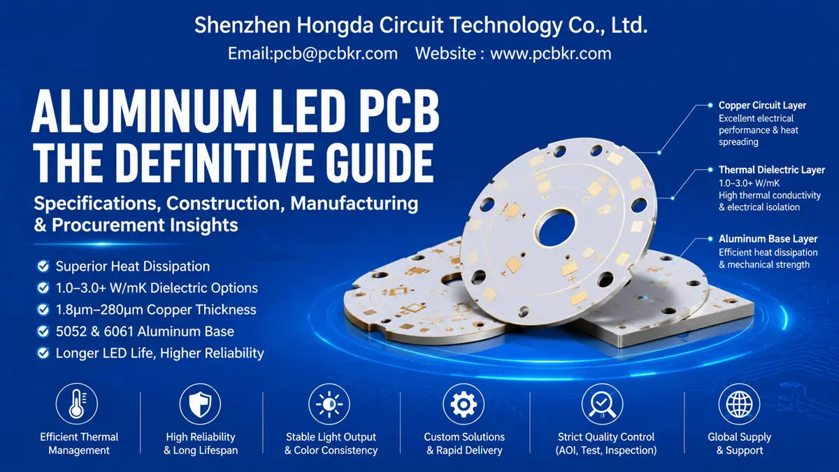
Aluminum LED PCB — Metal Core Circuit Solutions for High-Heat LED Applications
When an LED lighting product fails prematurely in the field, the root cause usually traces back to one component: the substrate beneath the LEDs. Standard FR-4 boards trap heat. Junction temperatures climb. Solder joints fatigue. Lumen output degrades within months, not years. The aluminum LED PCB—also known as an LED metal PCB, metal core PCB (MCPCB), or insulated metal substrate (IMS)—exists specifically to prevent this failure mode.
At Shenzhen Hongda Circuit Technology Co., Ltd., we manufacture aluminum LED PCBs for clients who cannot tolerate thermal drift or batch inconsistency. Our facility in Shenzhen runs automated LDI laser direct imaging, precision vacuum lamination, and multi-station AOI inspection to deliver aluminum LED PCB boards with dielectric thermal conductivity options from 1.0 W/mK to 3.0 W/mK and beyond. If you are evaluating suppliers, comparing quotes, or validating whether an aluminum substrate fits your LED project, this page maps every specification, structural detail, and quality checkpoint you need before releasing a purchase order.
What Is an Aluminum LED PCB? Definition and Core Function
An aluminum LED PCB is a metal-core printed circuit board that uses aluminum as its base substrate instead of fiberglass (FR-4). It is engineered to serve two simultaneous functions: electrical interconnection for LED components and conductive heat dissipation away from the LED junction.
Unlike conventional PCBs where thermal management is an afterthought, the aluminum PCB for LED lighting is designed around heat flow. The aluminum base layer draws thermal energy from the LED package through a thin thermally conductive dielectric, then spreads that heat across the entire board area. This structural approach keeps LED junction temperatures within rated limits, preserving color stability and extending operational life.
At Hongda Circuit, we classify the LED metal PCB as a thermal-mechanical system first and an electrical circuit second. The aluminum base also provides mechanical rigidity, making these boards suitable for fixtures that experience vibration, thermal cycling, or physical stress during assembly and operation.
Aluminum LED PCB Construction — Three-Layer Thermal Architecture
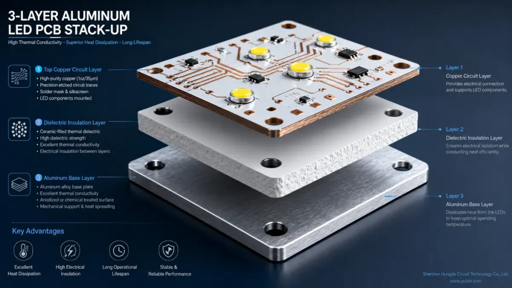
3-Layer Aluminum LED PCB Stack-Up Architecture & Thermal Dissipation Path
Understanding the stack-up is critical for procurement. The performance of a metal core LED PCB depends on how well its three layers work together. Weakness in any one layer creates a thermal bottleneck that no amount of external heat sinking can overcome.
Circuit Layer: Copper Foil for Current and Heat Spreading
The top layer is etched copper foil that forms the electrical traces and LED solder pads. Copper thickness directly impacts both current-carrying capacity and lateral heat spreading. At Hongda Circuit, our custom aluminum PCB manufacturing line supports copper foil thicknesses from 1.8 µm up to 140 µm (approximately 0.05 oz to 4 oz), with extended capability up to 280 µm for high-current power LED arrays.
Thicker copper reduces resistive heating and improves thermal spreading across the board surface. For COB LED modules and high-power strip designs, we typically recommend 70 µm (2 oz) or 105 µm (3 oz) copper to prevent localized hot spots under the LED thermal pads.
Thermal Insulation Layer: The Critical Dielectric Interface
The dielectric layer sits between the copper circuit and the aluminum base. This is the most technically demanding layer in an aluminum LED PCB. It must provide electrical isolation while simultaneously conducting heat—a combination that standard FR-4 materials cannot achieve.
We utilize high-performance aluminum PCB dielectric material systems including IMS-H01, IMS-H02, and LED-0601 grades. These ceramic-filled epoxy systems deliver thermal conductivity ratings from 1.0 W/mK to 3.0 W/mK, with low thermal resistance and the viscoelastic properties needed to withstand mechanical stress and thermal cycling without delamination.
Procurement teams should note: the dielectric—not the aluminum—is the thermal bottleneck. A supplier quoting an aluminum PCB board without specifying dielectric thermal conductivity is omitting the single most important performance parameter.
Aluminum Base Layer: Thermal Mass and Mechanical Backbone
The aluminum substrate provides the final heat sink path and structural foundation. We work with 5052 H32 alloy for applications requiring bending and mechanical forming, and 6061 T6 alloy for designs that demand higher strength and CNC machining precision.
The base thickness typically ranges from 0.8 mm to 3.0 mm, selected based on thermal capacity requirements and mechanical compatibility with the final fixture housing. The aluminum base is nonmagnetic, lightweight (density 2.7 g/cm³), and offers natural corrosion resistance when properly surface-treated.
Key Features of Aluminum LED PCB — Why Engineers Specify Metal Core
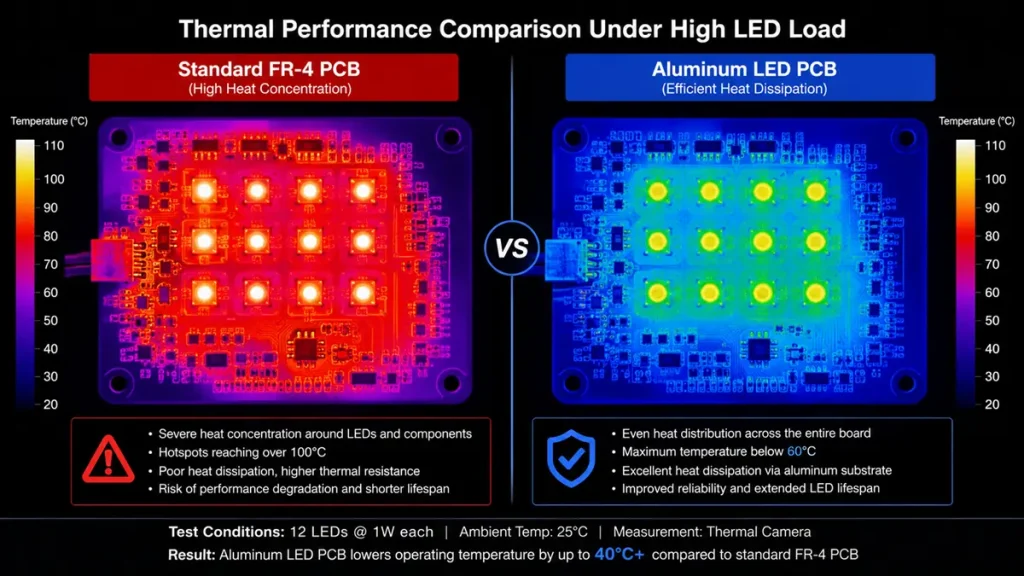
Thermal Imaging Comparison: Standard FR-4 PCB vs. Aluminum LED PCB Under High Load
When procurement teams evaluate an aluminum PCB board supplier, they need to articulate the technical advantages to internal stakeholders. Here are the five defining characteristics that distinguish aluminum LED PCBs from standard substrates.
Good Heat Dissipation Through Metal Substrate Conduction
The primary reason engineers switch to an LED metal PCB is thermal performance. Aluminum conducts heat approximately 200 W/mK—orders of magnitude beyond FR-4’s 0.3–0.4 W/mK. The PCB itself becomes part of the thermal solution, drawing heat away from the LED junction faster than ambient convection or external heat sinks alone.
Low Thermal Resistance Design
Hongda Circuit’s aluminum LED PCB stack-ups use thin dielectric layers—typically 75 µm to 150 µm—to minimize thermal resistance between the copper circuit and the aluminum base. This low-resistance path is essential for high-power LED applications where every degree of junction temperature reduction translates directly to longer lumen maintenance life.
Electrical Insulation With Thermal Conductivity
The ceramic-filled dielectric achieves a critical balance: it withstands breakdown voltages exceeding 3 kV while conducting heat efficiently. This allows the aluminum base to remain electrically neutral (grounded or floating) while functioning as a thermal spreader—something impossible with bare metal construction.
High Mechanical Strength for Assembly Durability
Aluminum provides superior rigidity compared to fiberglass laminates. This strength protects the board during mechanical processing—drilling, punching, shearing, V-scoring—and during final product assembly when mounting pressure is applied. For outdoor lighting and industrial fixtures subject to vibration, this durability is non-negotiable.
Nonmagnetic Material Properties
Aluminum is inherently nonmagnetic. In applications where electromagnetic interference or magnetic field sensitivity is a concern—such as medical lighting or precision instrumentation—the aluminum PCB for LED lighting offers a clean magnetic signature that copper or steel alternatives cannot match.
Aluminum LED PCB Specifications — The Procurement Reference Table
This table represents the core data buyers need to validate during supplier qualification. All parameters reflect Hongda Circuit’s actual manufacturing capabilities.
| Specification | Hongda Circuit Capability | Procurement Note |
|---|---|---|
| PCB Type | Aluminum LED PCB, LED Metal PCB, MCPCB, IMS | Match naming convention to your BOM |
| Base Material | Aluminum 5052 H32, 6061 T6 | 5052 for forming; 6061 for machining |
| Structure | Copper foil + dielectric + aluminum base | Three-layer standard stack-up |
| Board Thickness | 0.8 mm, 1.0 mm, 1.2 mm, 1.5 mm, 2.0 mm, 2.5 mm, 3.0 mm | Thicker base = higher thermal mass |
| Copper Thickness | 1.8 µm, 35 µm, 70 µm, 105 µm, 140 µm (up to 280 µm) | Higher current = thicker copper |
| Dielectric Thermal Conductivity | 1.0 / 1.5 / 2.0 / 3.0 W/mK | Specify based on LED wattage density |
| Dielectric Breakdown Voltage | > 3 kV | Critical for high-voltage LED drivers |
| Solder Mask Color | White (high reflectivity), black, green | White mask increases fixture lumens |
| Surface Finish | Gold Plated, HASL, OSP, Immersion Gold | ENIG recommended for flatness |
| Environmental Process | Lead-Free, RoHS compliant | Mandatory for EU and North America |
| Mechanical Processing | Drilling, punching, shearing, cutting, V-scoring | Match to your fixture assembly method |
| Flammability Rating | UL 94V-0 available | Required for certified lighting products |
| Max Panel Size | Up to 490 x 590 mm | Confirm for large panel light designs |
Critical procurement rule: Never accept a quote that lists “standard aluminum PCB” without defining dielectric thermal conductivity, copper weight, and base alloy. These three variables determine whether the board will survive in the field or fail after 2,000 hours.
Surface Finishes for Aluminum LED PCB — Solderability and Protection Options
The surface finish protects exposed copper from oxidation and determines solder joint reliability during LED assembly. Hongda Circuit offers four primary finishes for aluminum LED PCB manufacturing, selected based on your assembly process and end-use environment.
Gold Plated Finish
Gold plating provides excellent oxidation resistance and reliable wire bonding compatibility. We recommend this finish for COB LED modules and applications where aluminum wire bonding directly to the PCB pad is required.
HASL (Hot Air Solder Leveling)
HASL remains the most cost-effective surface finish for aluminum PCB boards used in standard LED lighting. It delivers good solderability for through-hole and SMD components. Lead-free HASL is available for RoHS-compliant production.
OSP (Organic Solderability Preservative)
OSP provides a flat, coplanar surface ideal for fine-pitch LED packages where solder paste deposition consistency is critical. It is environmentally friendly and suitable for single-reflow assemblies.
Immersion Gold (ENIG)
Electroless Nickel Immersion Gold delivers a perfectly flat surface with exceptional solder joint reliability. For aluminum LED PCBs with small LED packages (2835, 3528, 5050) or BGA-style driver ICs, ENIG minimizes solder bridging and improves first-pass yield during SMT assembly.
Lead-Free and RoHS Process Compliance
All surface finish options are available in lead-free formulations. We provide material declarations and RoHS compliance documentation with every shipment for clients exporting to regulated markets.
Aluminum LED PCB Applications — Where Metal Core Becomes Essential
LED Lighting and Display Modules
The dominant application for aluminum LED PCBs is general and commercial LED lighting—downlights, panel lights, tube lamps, and display backlighting. In these products, the aluminum base replaces separate heat sink plates, reducing component count and assembly cost while improving thermal reliability.
Power Hybrid IC (HIC) Applications
Beyond visible lighting, LED metal PCBs serve as substrates for power hybrid integrated circuits where discrete power components and control logic share a common thermal base. The aluminum substrate provides both electrical grounding and thermal stabilization for voltage regulators, DC-DC converters, and motor control modules operating in thermally challenging environments.
Why Choose Aluminum for LED PCB? Material Selection Logic
Procurement teams often face internal pressure to reduce substrate cost by specifying FR-4. This decision is defensible only for very low-power indicator LEDs. Once LED power exceeds approximately 0.5 W per chip, or when multiple LEDs are densely packed, aluminum becomes the economically correct choice.
Aluminum offers a unique combination of properties that no other substrate material matches at comparable cost: thermal conductivity sufficient for most LED applications, mechanical strength for fixture integration, lightweight construction for shipping and installation, and full machinability for custom shapes and mounting holes.
For projects where LED junction temperature control is a design priority, the aluminum PCB for LED lighting is not an upgrade—it is the baseline requirement.
Aluminum LED PCB Manufacturing Considerations — What Buyers Must Verify
Before placing an order, confirm these four manufacturing dimensions with your supplier. At Hongda Circuit, we address each during our pre-production engineering review.
Material Selection Confirmation
Verify the aluminum alloy, dielectric material system (IMS-H01, IMS-H02, or LED-0601), target thermal conductivity, and electrical insulation requirements. Do not assume the supplier will default to the correct grade.
Board Thickness Tolerance
Standard aluminum LED PCB thicknesses range from 0.8 mm to 3.0 mm. Thicker bases improve thermal mass but increase weight and machining difficulty. We recommend 1.0–1.6 mm for most commercial lighting and 2.0–3.0 mm for high-power outdoor fixtures.
Mechanical Processing Capability
Confirm that your supplier can execute the drilling, punching, shearing, and cutting operations your design requires. Hongda Circuit uses CNC routing and precision punching equipment to maintain ±0.05 mm outline tolerance on aluminum substrates, preventing burrs that can compromise electrical isolation.
Surface Finish Compatibility
Match the surface finish to your LED assembly process. If you are using reflow soldering with small-pitch LED packages, specify ENIG or OSP rather than HASL to ensure coplanar pad surfaces.
Request an Aluminum LED PCB Quote — Shenzhen Hongda Circuit Technology
If you have reached this section, you are likely in the final stage of supplier evaluation. Send your Gerber files and aluminum LED PCB requirements to Hongda Circuit for a manufacturing review and firm quotation. We respond to all RFQs within 24 hours.
Request a Quote for Aluminum LED PCB: pcb@pcbkr.com
- Get Aluminum LED PCB Pricing
- Submit Gerber Files for DFM Review
- Contact an Aluminum LED PCB Specialist
Quote Request Form Fields:
- Name
- Business Email
- Company
- Project Application
- Board Dimensions
- Number of Layers
- Board Thickness
- Copper Thickness
- Aluminum Base Requirement (5052 / 6061)
- Thermal Insulation Requirement (1.0 / 1.5 / 2.0 / 3.0 W/mK)
- Surface Finish (Gold Plated / HASL / OSP / Immersion Gold)
- Required Quantity
- Target Lead Time
- Gerber File Upload
- Additional Technical Requirements
Aluminum LED PCB FAQ — Procurement Decision Support
What is the difference between an aluminum LED PCB and a standard FR-4 PCB for LED lighting?
An aluminum LED PCB uses a metal base (typically 5052 or 6061 aluminum) with a thermally conductive dielectric layer to dissipate heat. FR-4 is a fiberglass-epoxy composite with thermal conductivity around 0.3–0.4 W/mK—insufficient for high-power LEDs. Aluminum substrates conduct heat at roughly 200 W/mK through the base metal, while the dielectric layer (1.0–3.0 W/mK) provides the critical thermal bridge. For LED applications above 0.5 W per chip, aluminum is the standard substrate. FR-4 should be limited to low-power indicator LEDs or signal-only circuits.
What aluminum LED PCB thermal conductivity do I need for my high-power LED project?
Specify dielectric thermal conductivity, not base metal conductivity. For LED power densities below 1 W per chip, 1.0–1.5 W/mK dielectric is adequate. For 1–3 W LEDs in downlights or street lights, specify 2.0 W/mK. For COB modules or dense LED arrays above 100 W total, 3.0 W/mK or direct thermal path (DTP) construction is necessary. Always request the dielectric material grade (IMS-H01, IMS-H02, LED-0601) and thermal resistance data, not just a marketing number.
Can aluminum LED PCBs be customized for shape, thickness, and thermal performance?
Yes. A qualified custom aluminum PCB manufacturer can customize the aluminum alloy, board thickness (0.8–3.0 mm), copper weight (up to 4 oz), dielectric thermal conductivity (1.0–3.0 W/mK), solder mask color, surface finish, and outline shape. At Hongda Circuit, we machine custom profiles from your Gerber or DXF files. However, every custom parameter must be validated against manufacturing capability during DFM review. Submit your Gerber, mechanical drawing, and LED power specifications to receive a validated quote.
What surface finish is best for aluminum LED PCB assembly: HASL, ENIG, or OSP?
For standard through-hole LED assemblies with generous pad sizes, HASL is cost-effective. For fine-pitch SMD LEDs (2835, 3528, 5050) or automated reflow processes, ENIG (Immersion Gold) is superior due to its flat surface and reliable solder joint formation. OSP works well for single-reflow assemblies where cost sensitivity is high. For COB wire-bonding applications, Gold Plated is required. Match the finish to your assembly technology, not just your budget.
How do I verify a China aluminum LED PCB manufacturer before placing a volume order?
Demand three validation steps before committing to production:
First Article Inspection (FAI) with full dimensional report, copper thickness verification, and dielectric thermal conductivity confirmation.
Material certificates proving aluminum alloy grade, dielectric material system, and RoHS compliance.
Process transparency including equipment list (LDI, AOI, flying probe), lamination parameters, and quality system certification (ISO 9001).
Hongda Circuit provides FAI reports with prototype orders and welcomes third-party inspection agency visits to our Shenzhen facility. A supplier unwilling to share process details or material certificates is a sourcing risk, not a partner.
Company: Shenzhen Hongda Circuit Technology Co., Ltd.
Website:www.pcbkr.com
Specialization: Aluminum LED PCB, LED Metal PCB, MCPCB, and custom metal core circuit board manufacturing from prototype to volume production.
About Author
David Chen https://www.linkedin.com/in/pcbcoming
David Chen boasts an extensive professional background in PCBA manufacturing, PCBA testing, and PCBA optimization, with specialized expertise in high-precision PCBA fault analysis and rigorous PCBA reliability testing. The author has worked with high-layer-count server PCB fabrication, ultra-low-loss backplane stackups, and thermo-mechanical reliability optimization for AI infrastructure projects involving 112G and 224G PAM4 architectures. Skilled in complex circuit design and cutting-edge advanced PCB manufacturing processes, he delivers solutions that elevate product durability and performance across industrial applications. His technical articles focusing on PCBA manufacturing workflows and testing methodologies are widely cited by industry peers, research institutions, and technical platforms, solidifying his reputation as a recognized technical authority in the global circuit board manufacturing sector.