LED PCB Board Manufacturer & Custom Circuit Solutions
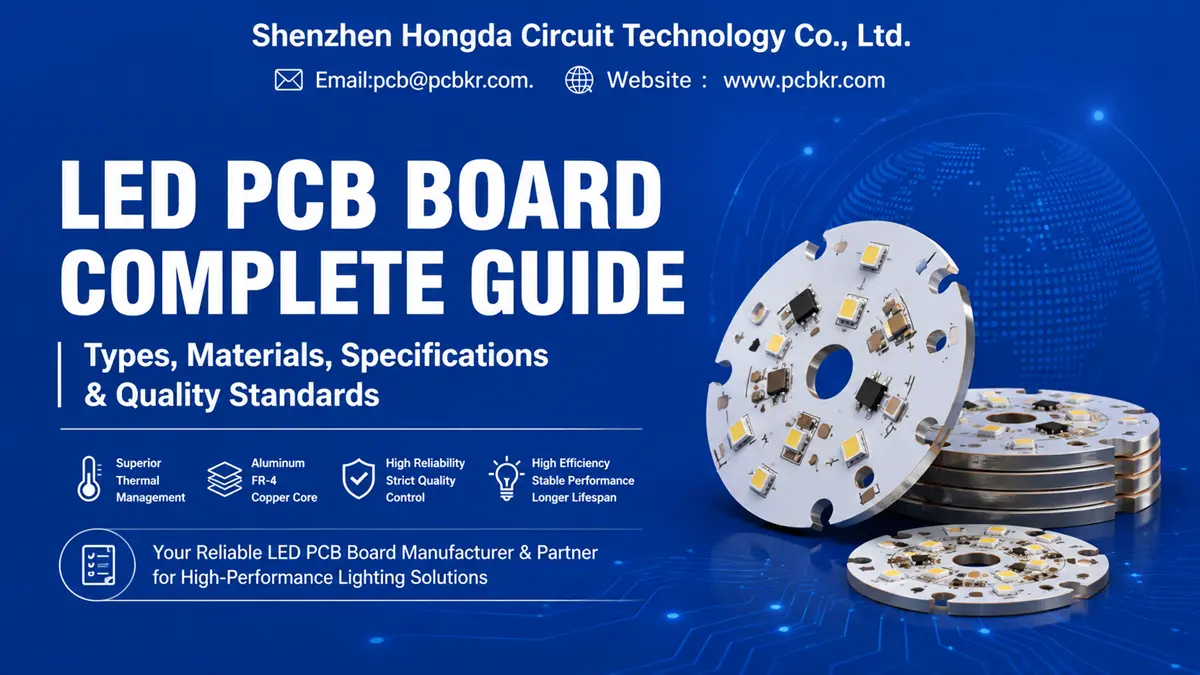
LED PCB board manufacturer understands that every lighting project that fails in the field can trace a root cause back to the circuit board. LED PCB board selection is not merely a sourcing checkbox—it is a thermal engineering decision that determines lumen maintenance, color stability, and product lifespan. At Shenzhen Hongda Circuit Technology Co., Ltd., we manufacture LED PCB circuit boards for clients who cannot afford thermal drift or batch‑to‑batch inconsistency. Our facility in Shenzhen runs automated LDI imaging, vacuum lamination, and multi‑station AOI to deliver aluminum LED PCB boards, FR‑4 LED PCB boards, and copper‑core configurations with dielectric thermal conductivity ratings from 1.0 W/mK to 3.0 W/mK and beyond.
If you are comparing quotes or validating a new LED PCB board supplier, this page maps every specification, material trade-off, and quality checkpoint you need before releasing a purchase order.
What Is an LED PCB Board?
An LED PCB board is a printed circuit board engineered specifically to mount, interconnect, and thermally manage light-emitting diode packages. Unlike generic circuit boards, an LED PCB circuit board must simultaneously handle low-voltage DC circuitry and high heat flux density. A standard 1 W LED can push junction temperatures past 85 °C in seconds without adequate heat sinking. Multiply that across a 100-LED array, and the PCB substrate becomes the primary thermal path.
The core function of any LED PCB board is to move heat away from the LED junction faster than it accumulates. This is why material selection—whether FR-4, aluminum, or copper—outranks trace layout in early design decisions. At Hongda Circuit, we treat the LED PCB board as a thermal-mechanical system first and an electrical interconnect second.
LED PCB Board Types — Matching Substrate Architecture to Thermal Load
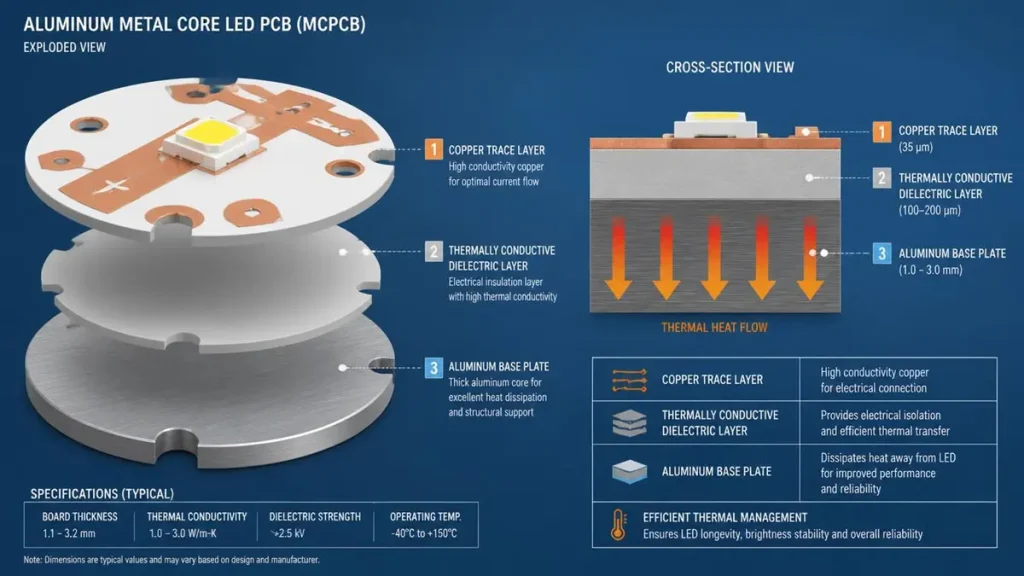
3D Exploded View and Cross-Section Diagram of an Aluminum Metal Core LED PCB (MCPCB) Architecture
Not every lighting application demands the same substrate. Choosing the wrong LED PCB board type inflates cost without benefit, or worse, masks a thermal failure that appears six months after installation. Below are the four primary LED PCB board configurations we manufacture.
Aluminum LED PCB Board for High-Heat Applications
The aluminum LED PCB board—also classified as a metal core LED PCB or MCPCB—remains the industry default for commercial and industrial lighting. The stack-up consists of a copper circuit layer, a thermally conductive dielectric, and an aluminum base plate (typically 5052 or 6061 alloy).At Hongda Circuit, our aluminum LED PCB boards are built with dielectric thermal conductivity options at 1.0 W/mK, 1.5 W/mK, 2.0 W/mK, and 3.0 W/mK. We also maintain white solder mask formulations with high reflectivity to maximize luminous efficacy in downlight and panel light applications. For engineers designing street lights, high-bay fixtures, or floodlights, aluminum LED PCB boards between 1.0 mm and 2.0 mm thickness provide the most cost-effective thermal performance window.
FR-4 LED PCB Board for Cost-Effective Designs
An FR-4 LED PCB board uses woven glass-reinforced epoxy laminate. Thermal conductivity sits around 0.3–0.4 W/mK, which limits its use to low-to-moderate power LED assemblies. However, FR-4 offers multilayer routing flexibility that aluminum cannot match. If your design integrates constant-current drivers, PWM controllers, or complex signal traces alongside LED strings, a multilayer FR-4 LED PCB board may be the only practical option.
We manufacture FR-4 LED PCB boards up to 8 layers with high-Tg 170 °C material for applications where thermal cycling resistance matters. For clients bridging cost and heat concerns, we integrate thermal vias and copper pours to improve heat spreading without switching to metal core construction.
Copper-Based LED PCB Board for Extreme Thermal Loads
When power density exceeds what aluminum can reliably handle, a copper-based LED PCB board becomes necessary. Copper delivers roughly 400 W/mK thermal conductivity—double that of aluminum. These boards are heavier and more expensive, but they are non-negotiable for automotive forward lighting, UV curing systems, and high-power COB LED modules.
Hongda Circuit produces copper-core LED PCB boards with thermoelectric separation (DTP) structures. In this architecture, the LED thermal pad contacts the copper base directly, bypassing the dielectric layer entirely. The result is thermal resistance figures that approach pure copper performance.
Single-Sided, Double-Sided, and Multilayer LED PCB Options
- Single-sided LED PCB board: Ideal for linear strip lights and simple bulb retrofits. Lowest cost, fastest turnaround.
- Double-sided LED PCB board: Allows LED mounting on one side and driver circuitry on the reverse. Common in compact retrofit lamps.
- Multilayer LED PCB board: Required when signal integrity, EMI shielding, or complex BGA routing coexist with LED thermal zones.
Our CNC drilling line handles minimum hole sizes down to 0.2 mm with ±0.05 mm positional accuracy, enabling dense via fields under LED thermal pads for multilayer constructions.
LED PCB Board Materials — Substrate Selection Matrix
Procurement teams often receive quotes for LED PCB boards without understanding why one material costs 40 % more than another. The table below isolates the decision variables.
| Material | Thermal Conductivity | Cost Index | Best Application |
|---|---|---|---|
| FR-4 | 0.3–0.4 W/mK | Low | Indicator lights, low-power decorative strips, LED displays |
| Aluminum (MCPCB) | 1.0–3.0 W/mK (dielectric) | Medium | Downlights, panel lights, street lights, high-bay fixtures |
| Copper-Core | Up to 400 W/mK (base) | High | Automotive headlights, UV LED, stage lighting, 200 W+ COB modules |
| Ceramic (Al₂O₃ / AlN) | 20–180+ W/mK | Premium | UV curing, medical phototherapy, high-density micro-LED arrays |
Critical note: The dielectric layer—not the metal base—determines the effective thermal conductivity in standard MCPCB construction. A 3.0 W/mK dielectric transfers heat three times faster than a 1.0 W/mK layer, directly lowering LED junction temperature and extending lumen maintenance life. When sourcing an LED PCB board, always specify dielectric thermal conductivity, not just base metal type.
LED PB Board Specifications — The Technical Checklist Buyers Must Verify
This section is the core of your vendor qualification process. Before issuing an RFQ, cross-reference the following LED PCB board specifications against your project requirements and our stated capabilities.
| Specification | Hongda Circuit Capability | Procurement Note |
|---|---|---|
| PCB Type | FR-4 LED PCB, Aluminum LED PCB, Copper-Core LED PCB, Ceramic LED PCB | Match substrate to thermal budget |
| Layer Count | 1 to 8 layers | Aluminum typically single/double-sided; FR-4 supports multilayer |
| Board Thickness | 0.6 mm to 3.0 mm | Thicker boards improve mechanical stability in long linear fixtures |
| Copper Thickness | 0.5 oz to 4 oz (18 µm to 140 µm) | Higher copper weight improves current carrying and heat spreading |
| Dielectric Thermal Conductivity | 1.0 / 1.5 / 2.0 / 3.0 W/mK (aluminum); higher on request | Specify based on LED wattage density |
| Minimum Trace/Space | 0.075 mm / 0.075 mm | Fine-pitch LED arrays require tight tolerances |
| Minimum Hole Size | 0.2 mm mechanical; 0.1 mm laser | Critical for thermal via density under LED pads |
| Solder Mask | White (high-reflectivity), black, green, blue | White mask increases light output by 5–10 % in reflector applications |
| Surface Finish | HASL, Lead-Free HASL, ENIG, OSP | ENIG recommended for aluminum boards due to flatness |
| Board Shape | Rectangular, circular, irregular (routed or scored) | Send .DXF or outline layer with Gerber |
| Flammability Rating | UL 94V-0 available | Required for North American lighting markets |
Red flag for buyers: If a supplier quotes an aluminum LED PCB board without specifying dielectric thermal conductivity, they are omitting the single most important thermal parameter. Demand the number.
LED PCB Board Thermal Management — Preventing Field Failures
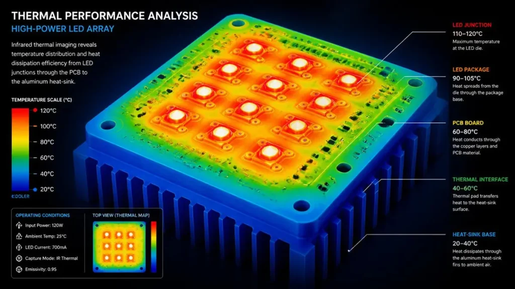
Thermal Performance Analysis and Infrared Heat Dissipation Map of High-Power LED Array
Thermal failure in LED systems rarely announces itself immediately. It manifests as gradual color shift, lumen depreciation, and eventual solder joint fracture. The LED PCB board is the first line of defense.
The Thermal Path Explained
Heat originates at the LED junction. It travels through the LED package slug, into the solder joint, across the copper trace, through the dielectric layer, and finally into the aluminum or copper base. The dielectric layer is the bottleneck. Even a thin 100 µm dielectric with 1.0 W/mK conductivity creates more thermal resistance than the entire 1.5 mm aluminum base beneath it.
Thermal Performance by Application Tier
| Heat Load | Recommended LED PCB Board | Rationale |
|---|---|---|
| < 0.5 W per LED | FR-4 LED PCB board | Cost-optimized; adequate with thermal vias |
| 0.5 W – 3 W per LED | Aluminum LED PCB board (1.0–2.0 W/mK) | Industry standard for commercial lighting |
| 3 W – 10 W per LED | Aluminum LED PCB board (2.0–3.0 W/mK) or copper-core | High-bay, street light, industrial |
| > 10 W per LED / COB | Copper-core or ceramic LED PCB board | Thermoelectric separation or DBC ceramic required |
At Hongda Circuit, our engineering team reviews every LED PCB board Gerber for thermal choke points before production. We flag insufficient copper area, missing thermal vias, and dielectric mismatches during DFM review—before your capital is committed to tooling.
LED PCB Board Applications — Industry-Specific Requirements
LED Lighting Fixtures
Downlights, track lights, and ceiling panels demand aluminum LED PCB boards with white solder mask to maximize reflector efficiency. Board thickness typically ranges 1.0–1.6 mm to interface with standard heat sinks.
LED Strips and Linear Modules
Single-sided flexible or rigid LED PCB boards dominate this segment. Hongda Circuit produces rigid strip boards up to 1200 mm in length with V-scoring for snap-fit assembly. Copper weight is typically 1–2 oz to handle series current without excessive voltage drop.
Street Lights and High-Power Outdoor Lighting
These fixtures run 50 W to 200 W+ in sealed enclosures with minimal air flow. An aluminum LED PCB board with 2.0 W/mK dielectric and 2 oz copper is the baseline. We recommend ENIG surface finish for outdoor humidity resistance.
Automotive LED Lighting
Automotive LED PCB boards must survive thermal cycling from -40 °C to 125 °C. Copper-core or high-Tg FR-4 with thermally reinforced dielectrics are standard. Hongda Circuit supports PPAP documentation and material traceability for automotive-tier clients.
UV LED and Horticultural Lighting
UV LEDs and high-PPFD grow lights push power densities past conventional aluminum limits. Ceramic LED PCB boards (Al₂O₃ or AlN) or copper-core DTP boards are typically required. We validate dielectric breakdown voltage (> 3 kV) for these high-stress applications.
Custom LED PCB Board Manufacturing — From Gerber to Production at Hongda Circuit
Procurement delays usually stem from unclear specifications, not factory capacity. We have structured our LED PCB board manufacturing workflow to eliminate ambiguity at the quoting stage.
Our Manufacturing Infrastructure
- LDI Laser Direct Imaging: Replaces traditional film exposure, achieving ±8 µm trace accuracy on fine-pitch LED arrays.
- Vacuum Hot Press Lamination: Ensures void-free dielectric bonding in multilayer and metal-core constructions.
- 6-Station Automated AOI: Catches open circuits, solder mask defects, and trace width deviations before boards leave the factory floor.
- High-Speed CNC Routing: Handles aluminum, copper, and FR-4 with dedicated tooling to prevent burr contamination.
- Flying Probe & Dedicated Test Fixtures: 100 % electrical continuity and isolation testing.
The Hongda Circuit Procurement Workflow
- Upload Gerber & Specs — Send your RS-274X Gerber, drill file, and mechanical drawing. Include LED power ratings and target thermal performance.
- DFM Engineering Review — Our engineers validate stack-up, thermal via density, annular ring margins, and solder mask windows within 24 hours.
- Quote Confirmation — You receive a firm quote with material certifications, lead time, and inspection criteria.
- Prototype Validation — First article inspection (FAI) with full dimensional report and thermal impedance data on request.
- Volume Production — Lot traceability, IPC-A-600 acceptability standards, and scheduled dock-date delivery.
Lead times: Standard aluminum LED PCB board prototypes ship in 5–7 working days. FR-4 multilayer prototypes in 7–10 working days. Volume schedules are locked at order confirmation.
LED PCB Board Quality and Inspection — Eliminating Sourcing Risk
The most expensive LED PCB board is the one that passes incoming inspection but fails after 2,000 hours of operation. Our quality system targets latent defects through process control, not just final screening.
Incoming Material Verification
- Aluminum base alloy verification (5052 / 6061 certification)
- Dielectric thermal conductivity batch testing
- Copper foil tensile and elongation checks
- Solder mask viscosity and cure response
In-Process Controls
- Etch uniformity: ±5 % copper weight tolerance across the panel
- Registration accuracy: Inner-to-outer layer alignment within ±0.05 mm for multilayer LED PCB boards
- Dielectric thickness: Measured by eddy current per panel quadrant
Final Inspection & Test
- Visual inspection: 40x magnification under IPC-A-600K criteria
- Dimensional CMM: Board thickness, hole diameter, slot width, outline tolerance
- Electrical test: 100 % netlist continuity and isolation (250 V test voltage, 10 MΩ minimum resistance)
- Thermal validation: Sample boards from each lot undergo thermal impedance testing to verify dielectric performance matches specification
Documentation Package
- Inspection report
- Material certificate of conformance
- RoHS / REACH declaration (upon request)
- UL 94V-0 traceability (where applicable)
Why Choose Hongda Circuit as Your LED PCB Board Supplier
We do not claim to manufacture every PCB type in existence. We specialize in LED PCB board fabrication where thermal performance and dimensional repeatability determine product success.
- Substrate breadth: FR-4, aluminum, copper-core, and ceramic LED PCB boards under one roof.
- Thermal specificity: Dielectric options from 1.0 W/mK to 3.0 W/mK, with engineering guidance on selection.
- Precision capability: 0.075 mm trace/space, 0.2 mm mechanical drill, laser imaging alignment.
- Procurement transparency: Fixed lead times, material certifications, and no hidden tooling charges on reorders.
- Volume flexibility: Prototype quantities from 5 pieces to volume schedules exceeding 50,000 pieces per release.
Hongda Circuit serves lighting OEMs in North America, Europe, and Asia-Pacific from our Shenzhen facility. We ship FOB Shenzhen, Hong Kong, or arrange DDP delivery through our logistics partners.
LED PCB Board FAQ — Procurement Decision Support
How do I choose between an aluminum LED PCB board and an FR-4 LED PCB board for my lighting project?
Base the decision on power density and thermal budget. If your LED array runs under 0.5 W per chip and you have auxiliary heat sinking, an FR-4 LED PCB board with thermal vias will save 20–40 % on substrate cost. Once you exceed 1 W per LED or operate in a sealed enclosure, an aluminum LED PCB board becomes necessary. The dielectric layer in an aluminum board conducts heat laterally through the metal base, preventing junction temperature creep that causes lumen depreciation. For commercial downlights, street lights, and high-bay fixtures, aluminum is the default. For signal-heavy designs with integrated drivers, multilayer FR-4 may be unavoidable.
What LED PCB board thermal conductivity do I need for high-power lighting?
Specify dielectric thermal conductivity, not base metal conductivity. A standard aluminum LED PCB board with 1.0 W/mK dielectric handles most 0.5–2 W LED applications. At 3–5 W per LED or in thermally constrained housings, upgrade to 2.0 W/mK or 3.0 W/mK dielectric. For COB modules above 100 W or automotive headlights, copper-core LED PCB boards with thermoelectric separation (bypassing the dielectric) are required. Always request thermal resistance (Rth) data from your supplier, not just a conductivity number.
What files does a custom LED PCB board manufacturer need to quote accurately?
At minimum, send RS-274X Gerber files, an Excellon drill file, a board outline (.DXF or Gerber profile), and a README specifying:
1. LED PCB board type (aluminum / FR-4 / copper / ceramic)
2. Layer count and board thickness
3. Copper weight (oz)
4. Dielectric thermal conductivity target
5. Solder mask color and surface finish
Quantity and delivery target
Without thermal requirements, a supplier will quote their default 1.0 W/mK aluminum construction—which may be insufficient for your application. Include LED power ratings and operating ambient temperature to receive a validated recommendation.
How can I verify a China LED PCB board supplier’s quality before placing a volume order?
Demand three things before committing to volume:
1. Prototype first article inspection (FAI) with dimensional report and electrical test data.
2. Material certifications proving aluminum alloy, dielectric thermal conductivity, and solder mask chemistry.
3. Factory audit evidence: ISO 9001 certification, equipment list (LDI, AOI, flying probe), and process control documentation.
Hongda Circuit provides FAI reports with every prototype order. We also welcome third-party inspection agency visits to our Shenzhen facility. A supplier unwilling to share process details or material certificates is a liability, not a partn
Why do LED PCB boards fail from overheating, and how do I prevent it during design?
Overheating failures stem from three design-sourcing gaps:
1. Underspecified dielectric: A 1.0 W/mK LED PCB board used in a 150 W floodlight will overheat because the dielectric cannot transfer heat fast enough. Match dielectric conductivity to wattage density.
2. Insufficient copper area: Narrow traces act as thermal resistors. Use 2 oz copper minimum for high-current LED strings, and place thermal vias directly under LED thermal pads.
3. Poor solder joint reliability: Thermal cycling cracks SAC305 solder joints if CTE mismatch between layers is excessive. High-Tg dielectrics and proper pad geometry reduce this risk.
Run thermal simulation before PCB fabrication. If you lack in-house simulation capacity, send Hongda Circuit your layout and LED datasheet. Our engineers perform thermal feasibility review at no charge during the quoting phase.
Request Your LED PCB Board Quote Today
Send your Gerber files and LED PCB board requirements to EMAIL: pcb@pcbkr.com . for engineering review and firm quotation. We respond to all RFQs within 24 hours with material recommendations, DFM feedback, and confirmed lead times.
About Author
David Chen https://www.linkedin.com/in/pcbcoming
David Chen boasts an extensive professional background in PCBA manufacturing, PCBA testing, and PCBA optimization, with specialized expertise in high-precision PCBA fault analysis and rigorous PCBA reliability testing. The author has worked with high-layer-count server PCB fabrication, ultra-low-loss backplane stackups, and thermo-mechanical reliability optimization for AI infrastructure projects involving 112G and 224G PAM4 architectures. Skilled in complex circuit design and cutting-edge advanced PCB manufacturing processes, he delivers solutions that elevate product durability and performance across industrial applications. His technical articles focusing on PCBA manufacturing workflows and testing methodologies are widely cited by industry peers, research institutions, and technical platforms, solidifying his reputation as a recognized technical authority in the global circuit board manufacturing sector.