Home Lighting PCB Solutions for LED Light and LED Bulb — Engineered by Shenzhen Hongda Circuit Technology Co., Ltd.
The global shift toward energy-efficient residential lighting has placed Home Lighting PCB at the center of every product development cycle. Whether you are sourcing an LED Light PCB for a new downlight series or a compact LED Bulb PCB for an A19 retrofit lamp, the board inside your fixture determines thermal stability, electrical safety, and ultimately, brand reputation. At Shenzhen Hongda Circuit Technology Co., Ltd., we manufacture LED circuit boards specifically for residential lighting OEMs who cannot afford field failures, color-shift, or premature lumen depreciation.
This guide is written for procurement managers, lighting engineers, and supply-chain directors who are actively evaluating LED PCB manufacturers in 2026. We address the technical decisions you face at every stage of the buying process — from substrate selection and Gerber review to pilot-run validation and volume scaling.
What Is a Home Lighting PCB? A Buyer’s Technical Foundation
A Home Lighting PCB is a printed circuit board engineered to carry, power, and thermally manage LED emitters inside residential fixtures. Unlike generic FR-4 boards, these PCBs must reconcile three conflicting demands: compact form factors, continuous heat flux, and cost targets that often sit below commercial or industrial tiers.
The Role of LED Light PCB in Modern Residential Fixtures
An LED Light PCB serves as the mechanical and electrical backbone of the fixture. It anchors SMD LEDs, routes constant-current traces, and — in the case of metal-core constructions — channels junction heat away from the emitter. For panel lights, ceiling lamps, and linear fixtures, the board is rarely a standard rectangle; it is contoured to match housing geometry, with mounting holes, wire-pad locations, and keep-out zones dictated by the lens and driver pocket.
At Hongda Circuit, we see a clear pattern among buyers who return for repeat orders: their initial prototypes failed not because of LED quality, but because the LED circuit board was treated as an afterthought. Thermal vias were missing. Copper weight was underspecified. The board warped after reflow. These are avoidable errors when the PCB supplier understands residential lighting physics.
LED Bulb PCB vs. General LED Circuit Board — What Buyers Need to Know
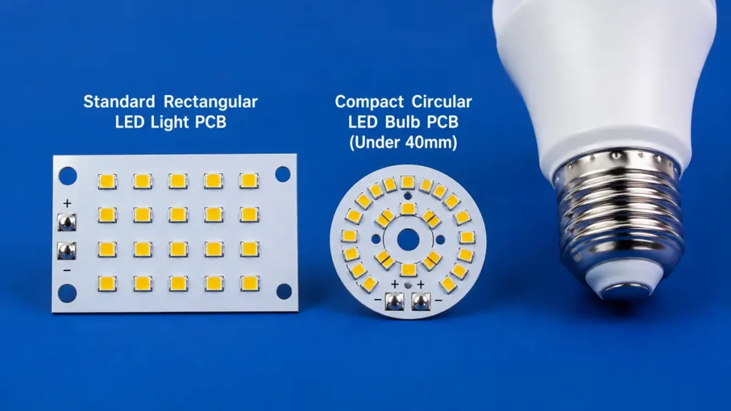
Comparison of Standard Rectangular LED Light PCB and Compact Circular LED Bulb PCB
An LED Bulb PCB is a subset of Home Lighting PCB with stricter spatial constraints. The board must fit inside a GU10, E27, or B22 base, often in a circular or annular shape under 40 mm in diameter. Because the enclosure is sealed and air-circulation is minimal, the LED Bulb PCB relies almost entirely on the substrate and MCPCB dielectric to move heat into the aluminum housing or plastic heat sink.
The distinction matters during procurement. A supplier who excels at large rectangular LED Light PCB panels may lack the routing precision or small-format punching capability required for high-volume LED Bulb PCB production. At Hongda Circuit, we maintain separate tooling libraries and CNC programs for bulb-class boards, ensuring edge tolerances within ±0.05 mm on diameters as small as 26 mm.
Core Functions of LED PCBs in Home Lighting Applications
Buyers who understand the three functional pillars of a Home Lighting PCB make faster, more defensible sourcing decisions. Here is how each pillar affects your product.
LED Component Mounting — Why PCB Layout Dictates Assembly Yield
The LED Light PCB must provide solder-pad geometries that match your chosen emitter package — typically 2835, 3030, or 5050 SMD LEDs for residential applications. Pad size, solder-mask opening, and surface finish (ENIG, OSP, or HASL) directly influence placement accuracy and void rates during SMT.
A common procurement pain point: a buyer switches LED vendors mid-project, only to discover the new emitter has a slightly different pad footprint. If the LED circuit board was not designed with pad-flexibility in mind, the entire PCB tooling set requires revision. Our engineering team at Hongda Circuit reviews LED datasheets during the DFM stage and recommends pad geometries that accommodate ±0.1 mm package variance across multiple LED brands.
Electrical Connection — Power Delivery Without Flicker or Dropout
Residential buyers are sensitive to flicker. The LED Bulb PCB trace network must maintain stable voltage delivery across all series-parallel strings, even when the driver output ripples at 120 Hz. Trace width, copper thickness, and via placement determine current-carrying capacity and voltage-drop uniformity.
For LED Light PCB designs above 12 W, we recommend 2 oz copper (70 μm) minimum on the LED layer. This reduces resistive heating in the traces themselves — a subtle but real source of efficiency loss that many low-cost suppliers ignore.
Heat Management — The Hidden Cost Driver in LED PCB Longevity
Junction temperature is the silent killer of residential LED products. Every 10°C rise above the rated junction temperature roughly halves LED lifetime. The Home Lighting PCB is the primary thermal path between the LED junction and the ambient environment.
For Aluminum LED PCB (MCPCB) designs, thermal conductivity of the dielectric layer is the critical specification. Standard 1.0 W/mK dielectrics suffice for 5–7 W bulbs. At 12 W and above, 2.0 W/mK or 3.0 W/mK thermal-conductive prepreg becomes necessary. We stock aluminum substrates from Kingboard, Polytronics, and Ventec, allowing us to match dielectric grade to your thermal simulation results rather than forcing a one-material-fits-all approach.
Home Lighting PCB Materials: How Procurement Teams Avoid Costly Mistakes
Material selection is where most LED PCB procurement errors originate. The wrong substrate creates a cascade of problems: inadequate heat spreading, solder-joint cracking, color-point drift, and warranty claims that erase margin.
Aluminum LED PCB (MCPCB) — The Standard for Thermal-Conscious Buyers
Aluminum LED PCB, also known as metal-core PCB (MCPCB), remains the dominant substrate for Home Lighting PCB applications above 5 W. The aluminum base — typically 1.0 mm to 2.0 mm thick — acts as a heat spreader, while the thermally conductive dielectric electrically isolates the copper circuit from the metal base.
At Shenzhen Hongda Circuit, our aluminum LED Light PCB production line handles single-sided, double-sided, and hybrid constructions. For LED Bulb PCB orders, we favor high-reflectivity white solder mask (≥85% reflectance at 450 nm) to maximize luminous efficacy without adding component cost. Our LDI (Laser Direct Imaging) system images traces down to 3 mil line/space on aluminum substrates, enabling dense LED arrays in compact bulb formats.
FR-4 LED PCB — When Cost, Not Heat, Drives the Decision
FR-4 is viable for low-wattage decorative lighting, indicator lamps, and battery-powered fixtures where thermal load is negligible. The advantage is cost: FR-4 LED circuit boards can be 20–40% less expensive than aluminum equivalents at equivalent area and layer count.
However, we caution buyers against specifying FR-4 for enclosed LED Bulb PCB designs above 9 W. The glass-epoxy substrate has poor through-thickness thermal conductivity (~0.3 W/mK). In a sealed housing, junction temperatures climb rapidly, accelerating lumen depreciation. If your target fixture is a high-power retrofit lamp, Aluminum LED PCB is not optional — it is a reliability requirement.
Material Selection Checklist Every LED PCB Buyer Should Demand
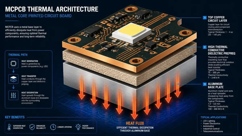
3D Cutaway of MCPCB Thermal Architecture and Layer Structure
Before you request a quote, verify these six parameters with your LED PCB manufacturer:
- LED Power Density — Watts per square centimeter on the board surface.
- Fixture Structure & Airflow — Is the housing open, vented, or fully sealed?
- LED Emitter Layout — Array density and spacing; single-chip vs. multi-chip.
- Thermal Budget — Maximum allowable junction temperature from your LED datasheet.
- PCB Thickness & Mechanical Fit — Clearance to the driver, lens, and housing clips.
- Volume & Cost Target — Prototype (100 pcs) vs. mass production (100,000+ pcs) may justify different material grades.
Our engineers at Hongda Circuit run thermal simulations using these inputs to recommend the lowest-cost substrate that still meets your lifetime target. We do not upsell 3.0 W/mK aluminum to a 5 W decorative lamp, nor do we approve FR-4 for a 15 W ceiling panel.
LED Light PCB Design Considerations That Determine Manufacturing Success
A well-designed Home Lighting PCB reduces assembly defects, simplifies procurement, and accelerates time-to-market. These are the design factors our DFM team reviews daily.
PCB Shape and Dimensions — Matching Your Fixture Housing
LED Light PCB for residential fixtures rarely conform to standard panel sizes. Downlight boards are typically round (Ø 68 mm to Ø 180 mm). Panel-light boards are square or rectangular (120×120 mm to 300×300 mm). LED Bulb PCB boards are annular or small-diameter circles.
We machine custom outlines on six-axis CNC routing stations with 0.1 mm positional accuracy. For high-volume LED Bulb PCB orders, we recommend steel-rule die punching to reduce per-unit routing time by 60%. The key procurement question is: does your supplier have the tooling library and fixture experience to match your housing without iterative back-and-forth? At Hongda Circuit, we maintain a database of over 400 residential lighting outlines, reducing NPI lead times for common form factors.
LED Layout Optimization — Spacing, Light Uniformity, and Thermal Balance
LED spacing on the LED circuit board determines both optical uniformity and thermal cross-talk. Tightly packed arrays create hotspots where center LEDs run 15–20°C hotter than edge LEDs. Overly sparse arrays require larger, more expensive optics to blend individual emitter images.
Our recommendation: maintain a minimum LED-to-LED pitch of 1.5× the LED package width for 2835 emitters, and 2× for 5050 emitters. This provides adequate thermal isolation while keeping the board area efficient. For LED Panel Light PCB designs, we also review copper pour patterns to ensure heat is distributed evenly across the aluminum base before reaching the housing interface.
Circuit Routing for Home Lighting — Current Capacity and Signal Integrity
Residential LED Light PCB designs are electrically simple — typically single-layer or double-layer — but current capacity is often underestimated. A 15 W, 120 V fixture drawing 125 mA through a 0.5 mm trace at 1 oz copper will experience measurable resistive heating. Over 25,000 hours, that heating degrades solder-mask adhesion and can open the trace.
We specify trace widths using IPC-2152 standards, adjusted for the elevated temperatures common in Home Lighting PCB environments. For LED Bulb PCB designs where space is constrained, we use teardrop pad connections and copper thieving to balance etch uniformity and current density.
Mounting and Assembly Integration — DFM from Day One
The best LED PCB design is useless if it cannot be physically secured inside the fixture. We review mounting-hole locations, standoff heights, wire-pad accessibility, and connector orientation during the Gerber review phase. For LED Bulb PCB products, we verify that the board edge does not interfere with the lamp-base crimping operation — a failure mode we have seen destroy entire pilot runs at other factories.
LED Bulb PCB Specifications — The Complete Procurement Reference
When you are ready to source, clarity in your specification package determines quote accuracy and first-article success. Here is what a professional LED PCB buyer communicates upfront.
10 Parameters Buyers Must Verify Before Placing an Order
- PCB Type — Single-sided MCPCB, double-sided MCPCB, or FR-4?
- Substrate Material — Aluminum alloy (1100, 5052), thermal conductivity grade.
- PCB Thickness — Typically 1.0 mm, 1.2 mm, or 1.6 mm for bulb applications.
- Copper Weight — 1 oz (35 μm) standard; 2 oz (70 μm) for high-current strings.
- LED Emitter Package — 2835, 3030, 5050 — this determines pad geometry.
- Board Outline — Diameter, annular ring width, mounting-hole pattern.
- Power Input — AC line voltage (120 V / 230 V) or DC driver output?
- Surface Finish — OSP (cost-driven), ENIG (reliability-driven), or HASL.
- Order Quantity — Prototype (100–500 pcs), pre-production (1,000–5,000 pcs), or mass (50,000+ pcs).
- PCBA Requirement — Bare board only, or turnkey assembly with LEDs and passive components?
Quotation Checklist — What to Send Your LED PCB Manufacturer
To receive an accurate, binding quote within 24 hours, provide your LED PCB supplier with:
- Gerber files (RS-274X format) for all copper layers, solder mask, and silkscreen.
- Board dimensions and a mechanical drawing or PDF outline.
- Fixture type — Downlight, bulb, panel, strip, or custom.
- Target volume and annual forecast.
- Substrate preference — Or request our thermal recommendation.
- Thickness and copper weight requirements.
- PCBA scope — Bare PCB, or PCB + component assembly?
- Packaging and delivery — Vacuum-sealed, anti-static, labeled by SKU?
At Hongda Circuit, our quote engineers review these inputs against our material inventory and capacity calendar. If your LED Bulb PCB design calls for a non-standard 1.5 mm aluminum substrate with 2 oz copper and white high-reflectivity mask, we confirm material availability before quoting — eliminating the “sorry, we cannot source this” conversation that wastes weeks at less prepared factories.
How Shenzhen Hongda Circuit Technology Manufactures Home Lighting PCB at Scale
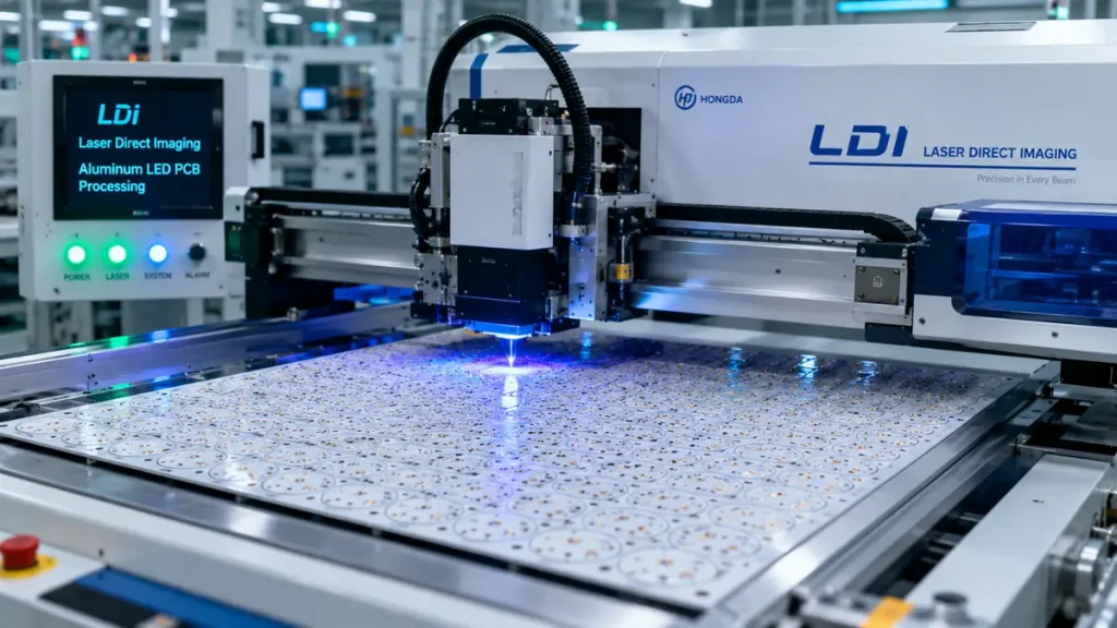
Automated LDI Laser Direct Imaging Processing Aluminum LED PCB Panel
Procurement teams in 2026 are not just buying boards; they are buying manufacturing capability, traceability, and supply-chain resilience. Here is how our facility in Shenzhen supports Home Lighting PCB programs from prototype to high-volume production.
Advanced LDI Imaging and Precision Etching for Fine-Line LED PCBs
We replaced traditional UV-contact exposure with Laser Direct Imaging (LDI) on our aluminum LED Light PCB line. LDI eliminates phototool degradation, maintains ±8 μm trace accuracy, and supports 3 mil line/space geometries — critical when packing 60+ LEDs onto a 40 mm LED Bulb PCB. For etching, we use horizontal spray-etch lines with real-time specific-gravity monitoring, ensuring uniform trace width across the entire panel and across production lots.
Automated AOI and X-Ray Inspection — Zero-Defect Commitment
Every Home Lighting PCB undergoes 100% automated optical inspection (AOI) after etching. We check for open circuits, shorts, pad geometry deviations, and solder-mask registration errors. For double-sided LED circuit boards and via structures, we add X-ray inspection to verify barrel plating integrity and hidden-layer alignment.
Our defect-tracking database is lot-traceable by date code, material batch, and machine ID. If a field issue ever arises, we can isolate the root cause to a specific process window within hours — not days.
From LED PCB Prototype to Mass Production — Flexible Capacity Model
We understand the residential lighting product cycle: a 500-piece prototype validates the design, a 3,000-piece pilot run tests the market, and a 50,000-piece order follows if the fixture sells. Our factory is structured for this stair-step scaling.
- Prototype: 2–5 day turnaround for single-sided Aluminum LED PCB.
- Pilot: 5–8 days with dedicated NPI engineers who monitor first-article build.
- Mass Production: 20,000+ square meters monthly capacity across four automated PCB lines, with Kanban-managed raw-material inventory to prevent aluminum substrate shortages.
PCBA Capability — LED Component Sourcing and Turnkey Assembly
Many LED PCB buyers prefer turnkey PCBA to reduce vendor count and assembly risk. Our SMT floor runs Yamaha and Panasonic high-speed placement systems, capable of 01005 passive placement and 0.3 mm BGA accuracy. For LED Bulb PCB assembly, we maintain consignment partnerships with major LED brands (Samsung, Seoul Semiconductor, NationStar) and can source, assemble, and test complete lamp modules under one roof.
Our reflow ovens use 10-zone thermal profiling with nitrogen atmosphere, minimizing oxidation on LED Light PCB solder joints and ensuring consistent wetting across high-thermal-mass aluminum boards.
Quality Control for LED Light PCB — What Happens Before Your Boards Ship
Quality is not an inspection step; it is a system. Our QC protocol for Home Lighting PCB addresses the failure modes that matter in residential environments.
Dimensional and Electrical Verification
- Outline tolerance: ±0.05 mm on CNC-routed LED Bulb PCB; ±0.1 mm on panel-light formats.
- Hole position: ±0.03 mm for mounting and wire-pad holes.
- Electrical test: 100% flying-probe or bed-of-nails testing for opens, shorts, and resistance values.
- Surface finish verification: ENIG thickness 1.0–3.0 μm; OSP film integrity by wetting balance.
Thermal Performance Validation for Aluminum LED PCB
For new Aluminum LED PCB designs, we conduct thermal imaging under loaded conditions. A representative board is populated with LEDs, powered at rated current, and monitored with an infrared camera until steady-state temperature is reached. If the measured board temperature exceeds the thermal simulation prediction by more than 5°C, we halt the lot and re-verify dielectric conductivity and copper coverage.
Documentation and Traceability for Every Batch
Each shipment includes a Certificate of Conformance, material data sheets, and — upon request — IPC test reports. All Home Lighting PCB lots are serialized and linked to raw-material batch numbers, enabling full traceability for warranty claims or regulatory audits.
FAQs Every LED PCB Buyer Searches on Google Before Choosing a Supplier
What is the difference between an LED Light PCB and a standard circuit board?
An LED Light PCB is purpose-built for thermal management and optical integration. Standard FR-4 boards lack the thermal conductivity required for high-power LED emitters. Home Lighting PCB designs use aluminum or thermally enhanced substrates, white reflective solder mask, and pad geometries optimized for SMD LED packages. A generic circuit board will overheat, yellow, and fail prematurely in a residential fixture.
How do I choose between aluminum and FR-4 for my LED Bulb PCB?
Choose Aluminum LED PCB (MCPCB) if your fixture runs above 5 W, operates in a sealed housing, or targets a lifetime above 25,000 hours. Choose FR-4 only for low-wattage decorative lamps, battery-powered fixtures, or cost-sensitive indicators where heat is not a limiting factor. When in doubt, send your LED datasheet and housing drawings to pcbkr.com; our engineers will model the thermal path and recommend the most cost-effective substrate.
What information does an LED PCB manufacturer need to give me an accurate quote?
Provide Gerber files, board dimensions, target quantity, substrate preference (or request guidance), copper weight, surface finish, and whether you need bare boards or full PCBA. For LED Bulb PCB orders, also specify the lamp-base type (E27, GU10, B22) and any mechanical constraints. The more complete your package, the faster we can validate DFM and confirm lead time.
How can I verify that a China LED PCB supplier will deliver consistent quality?
Look for four indicators: (1) ISO 9001 and ISO 14001 certifications with current audit records; (2) in-house AOI, X-ray, and electrical test capability — not outsourced spot-checking; (3) a documented DFM review process that catches errors before tooling; and (4) lot traceability linking your boards to raw-material batches. At Shenzhen Hongda Circuit, we welcome virtual factory tours and provide first-article inspection reports with every pilot run.
What is the typical lead time for custom LED Light PCB prototypes?
For single-sided Aluminum LED PCB prototypes, 5–7 business days is standard at pcbkr.com. Double-sided or complex-outline LED Light PCB prototypes require 7–10 days. If you need turnkey PCBA with LED component sourcing, add 3–5 days for material procurement and assembly. Rush services are available for time-sensitive residential lighting launches.
Request a Custom Home Lighting PCB Quote from pcbkr.com
If you are sourcing LED Light PCB, LED Bulb PCB, or turnkey LED PCB Assembly for residential lighting, send your requirements to Shenzhen Hongda Circuit Technology Co., Ltd. We review Gerber files, run thermal simulations, and deliver prototype-to-production solutions with the traceability and consistency that global lighting brands demand. Email:pcb@pcbkr.com
About Author
David Chen https://www.linkedin.com/in/pcbcoming
David Chen boasts an extensive professional background in PCBA manufacturing, PCBA testing, and PCBA optimization, with specialized expertise in high-precision PCBA fault analysis and rigorous PCBA reliability testing. The author has worked with high-layer-count server PCB fabrication, ultra-low-loss backplane stackups, and thermo-mechanical reliability optimization for AI infrastructure projects involving 112G and 224G PAM4 architectures. Skilled in complex circuit design and cutting-edge advanced PCB manufacturing processes, he delivers solutions that elevate product durability and performance across industrial applications. His technical articles focusing on PCBA manufacturing workflows and testing methodologies are widely cited by industry peers, research institutions, and technical platforms, solidifying his reputation as a recognized technical authority in the global circuit board manufacturing sector.