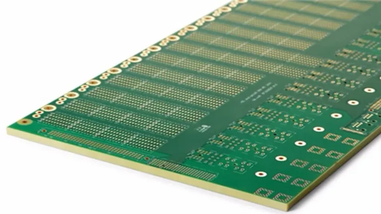
Battery Management System PCBA: How Can OEMs Choose the Right Supplier?
A reliable Battery Management System PCBA supplier must do more than manufacture a circuit board. OEMs need to verify PCB fabrication capability, component sourcing controls, assembly quality, electrical test coverage, and production traceability. The right supplier should also clarify which requirements are covered by manufacturing inspection, which require application-specific functional testing, and which remain the responsibility of the battery system designer.
For battery manufacturers, energy storage companies, EV developers, and industrial electronics OEMs, these distinctions help prevent avoidable design changes, production delays, inconsistent measurements, and costly rework.
Why Should OEMs Evaluate a Battery Management System PCBA Supplier Carefully?
A battery management system monitors battery conditions and helps control functions such as overvoltage protection, undervoltage protection, current monitoring, temperature monitoring, and cell balancing. The PCBA is the physical implementation of these electronic functions, but its manufacturing quality alone cannot guarantee that the complete battery system will operate safely.
A supplier evaluation should therefore cover three separate areas:
- PCB manufacturing: Can the factory manufacture the specified layer stack-up, copper thickness, dimensions, holes, vias, and surface finish?
- PCBA assembly: Can the supplier assemble the specified components and control soldering, component placement, inspection, and approved material usage?
- Electrical and functional verification: Can the supplier perform the tests agreed for the project and provide the corresponding results?
OEMs should also check whether the supplier can work with controlled design files, an approved bill of materials (BOM), documented test procedures, and an agreed change-management process.
A supplier with sophisticated equipment is not automatically the right supplier for every BMS project. Buyers should match the factory’s demonstrated capabilities to the actual design, risk level, production volume, and required evidence.
Product Details – Battery Management System PCBA
Battery Management System PCBA is an assembled printed circuit board designed for battery monitoring, protection, and control applications. Depending on the system architecture, it may integrate battery-monitoring ICs, microcontrollers, current-sensing circuits, temperature-sensing interfaces, communication interfaces, and cell-balancing control circuits.
The design and manufacturing requirements depend on the target application, electrical specifications, PCB structure, materials, copper thickness, component selection, and assembly process. A suitable manufacturing partner should review the released design package and clarify any manufacturing or assembly constraints before production.
Product Features
- Battery Monitoring: Supports battery-related measurement circuits according to the approved design.
- Protection and Control: Implements designated protection and control functions through the specified components and circuitry.
- Cell Balancing: Supports passive or active balancing circuits according to the BMS architecture.
- Communication Interfaces: May include CAN, UART, I²C, SMBus, or other interfaces where specified by the design.
- Customized PCB Fabrication: PCB structure, material, copper thickness, and other manufacturing parameters are selected according to project requirements.
- PCBA Manufacturing: Assembly requirements are defined by the BOM, component packages, board construction, and production specifications.
- Inspection and Testing: Inspection and electrical or functional tests are selected according to the agreed quality plan and test requirements.
Applications
- Lithium-ion battery packs
- Battery energy storage systems
- Electric mobility equipment
- Industrial battery-powered equipment
- Portable power products
- Other battery-powered electronic systems
The actual functions and application suitability of each Battery Management System PCBA depend on its architecture, circuit design, selected components, firmware, and system-level safety requirements.
Data Sheet – Battery Management System PCBA
The exact materials and specifications of a Battery Management System PCBA depend on the battery architecture, electrical load, sensing accuracy, thermal environment, insulation requirements, and mechanical design. The following table provides a starting point for engineering review; final values must be confirmed against the approved design documents.
| Parameter | Specification / Information Required |
|---|---|
| Product Type | Battery Management System PCBA |
| Product Function | Battery monitoring, protection, control, and other specified functions |
| Application | Defined by the OEM |
| Battery Chemistry | To be specified by the customer |
| Cell Configuration | To be specified by the customer |
| PCB Material | Selected according to electrical, thermal, mechanical, and insulation requirements |
| Number of Layers | According to the approved PCB design |
| Board Thickness | According to the approved PCB design |
| Copper Thickness | According to current, thermal, and manufacturing requirements |
| Minimum Line Width / Spacing | According to the design and confirmed manufacturing capability |
| Surface Finish | Selected according to component, soldering, and application requirements |
| Component Types | According to the approved BOM |
| Assembly Technology | SMT, through-hole, or mixed assembly as required |
| Communication Interface | According to the design, such as CAN, UART, I²C, or SMBus |
| Cell Balancing | Passive, active, or not applicable, according to the design |
| Component Sourcing | Customer-supplied or supplier-sourced, as agreed |
| Inspection | Defined in the project quality plan |
| Electrical / Functional Testing | Defined in the approved test specification |
| Customization | Based on the customer’s design and manufacturing requirements |
| Production Volume | Prototype, pilot, or production quantities as agreed |
The table is a project-planning reference, not a guarantee that every listed material, process, component, or test option is available for every order. Manufacturing limits, approved component availability, testing scope, and final specifications must be confirmed during quotation and engineering review.
How Can Buyers Verify a BMS PCBA Manufacturer’s Actual PCB Process Capability?
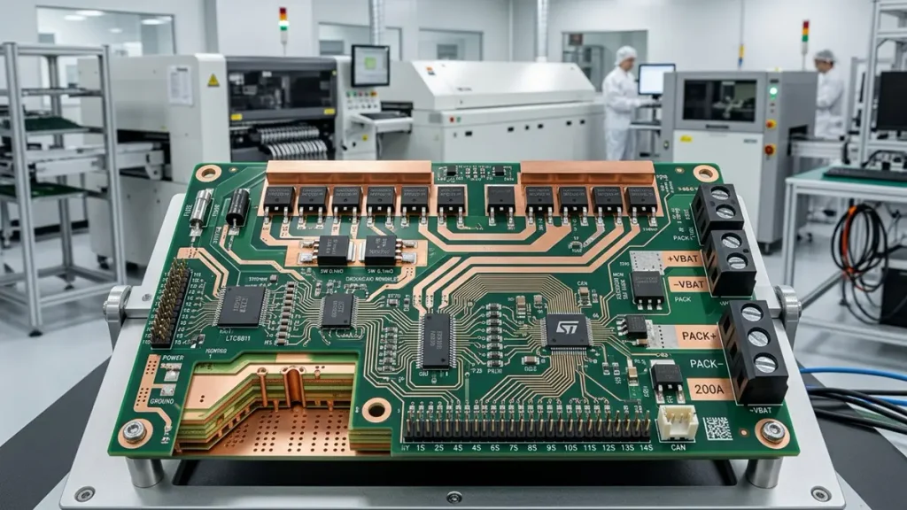
Battery Management System PCBA with high-current copper traces and multilayer PCB construction
Equipment lists are useful, but buyers should understand what each manufacturing process contributes to their design and what evidence the supplier can provide.
For BMS boards, this is particularly important when the design contains high-density circuitry, fine-pitch components, multiple layers, demanding registration requirements, or specialized via structures.
Which PCB fabrication capabilities should OEMs check?
| Manufacturing area | What buyers should verify | Why it matters |
|---|---|---|
| Laser Direct Imaging (LDI) | Minimum feature requirements, registration expectations, and applicable process capability | Fine-line patterns must match the released design |
| Lamination | Stack-up, material compatibility, and process requirements | Multilayer construction must follow the approved design |
| Laser drilling | Specified hole dimensions, tolerances, and via structures | Small vias must be suitable for the intended interconnection |
| Fine-line processing | Actual line/space capability for the selected construction | Capability must be assessed against the design, not just a headline specification |
| Electrical inspection | Applicable test method and acceptance criteria | Manufacturing defects need to be detected against defined requirements |
PCBKR has published information about its SCREEN Ledia LDI, Mitsubishi UV/CO₂ laser processing, picosecond laser processing, LAUFFER lamination equipment, and mSAP manufacturing capability. These are relevant starting points when discussing advanced PCB fabrication.
However, equipment specifications and process targets are not interchangeable with guaranteed production results. OEMs should confirm the applicable process, stack-up, tolerances, and validation evidence for their particular board.
For high-density BMS layouts, buyers can also review PCBKR’s HDI PCB manufacturing information where the design genuinely requires high-density interconnection.
How should buyers assess high-current BMS PCB construction?
High-current BMS designs may contain current-sensing circuits, switching devices, high-current connectors, balancing components, and power-distribution paths. These areas require coordinated electrical and thermal design.
During supplier review, ask whether the manufacturing team can identify constraints involving:
- Specified copper thickness and finished board construction.
- Trace geometry, via structures, and current-path requirements.
- Connector footprints, solder joints, and mechanical loading.
- Copper balance and multilayer stack-up requirements.
- Design-defined thermal relief and heat-spreading structures.
- Manufacturing deviations that could affect the approved electrical design.
Copper thickness alone does not establish the safe current rating of a PCB. Allowable current and temperature rise also depend on trace geometry, copper distribution, airflow, surrounding materials, operating conditions, and the relevant design criteria.
Where the design uses heavy copper, buyers can review PCBKR’s Heavy Copper PCB capability. The final suitability must still be confirmed against the actual board design and operating conditions.
What Should OEMs Review Before Releasing a BMS PCB for Manufacturing?
A BMS PCB should undergo a manufacturing-readiness review before production. Even when the schematic and basic design-rule checks are complete, unresolved issues involving power routing, component placement, thermal management, sensing accuracy, or assembly access can lead to rework, inconsistent measurements, and production delays.
OEMs should review the following areas before authorizing fabrication and assembly.
Power routing and copper design: Confirm that copper thickness, trace geometry, via structures, and connector interfaces match the approved electrical and thermal requirements. High-current paths should be evaluated against the intended operating conditions rather than copper thickness alone.
Component placement and thermal management: Check the placement of power components, balancing resistors, switching devices, and connectors. Confirm that the design accounts for heat dissipation, component spacing, and the intended operating environment.
Voltage and current sensing: Review sensitive measurement connections, grounding strategy, and the relevant component manufacturer’s layout recommendations. Measurement accuracy depends on the complete circuit design, component characteristics, layout, and calibration—not simply PCB fabrication quality.
Assembly and inspection access: Verify component footprints, polarity, connector orientation, test-point accessibility, and any mechanical constraints that could affect assembly or inspection.
Manufacturing documentation: Ensure that fabrication files, assembly drawings, BOM, stack-up specifications, and revision identifiers are consistent. Any proposed manufacturing changes should be documented and approved by the responsible party before implementation.
Before issuing a production order, OEMs should also clarify which issues the manufacturer will review, which design decisions remain the customer’s responsibility, and what evidence will be provided to confirm compliance with the agreed manufacturing requirements.
Which design issues should be checked before production?
1. Released design files
Confirm that Gerber or other agreed fabrication files, drill files, stack-up details, assembly drawings, BOM, and revision identifiers refer to the same design release.
2. High-current paths
Review the specified current paths, connectors, copper thickness, vias, and switching-device connections against the approved electrical design.
3. Measurement circuitry
Check whether the layout follows the component manufacturer’s recommendations for sensitive voltage and current measurement circuits, including relevant sensing connections and grounding requirements.
4. Thermal design
Confirm that power components, balancing resistors, switching devices, and other heat-generating parts are used within the design’s documented thermal limits.
5. Component footprints and assembly access
Verify connector orientation, component polarity, mechanical clearances, test-point access, and the feasibility of assembling and inspecting the board.
6. Manufacturing deviations
Agree how the supplier will report potential manufacturability issues, who approves changes, and how the approved revision will be controlled.
A useful pre-production review should produce documented findings and decisions. It should not imply that the PCB manufacturer has independently certified the complete circuit design or validated the battery system.
How Can OEMs Distinguish BMS PCBA Manufacturing Defects from Balancing Logic Problems?
Cell-balancing problems do not always originate in PCB fabrication or assembly. They can also result from component selection, circuit design, sensing errors, firmware configuration, battery conditions, or the test method.
A supplier investigation should begin by describing the observed failure and then separating possible causes.
| Observed symptom | Areas to investigate | Useful evidence |
|---|---|---|
| A balancing output does not activate | Circuit connections, component placement, solder joints, control signals, firmware conditions | Inspection findings, approved schematic, test logs |
| Cell-voltage readings appear inconsistent | Sensing path, reference components, input connections, measurement method, calibration settings | Reference measurements, test conditions, measurement records |
| Balancing behavior differs between cells | Channel configuration, component tolerances, sensing differences, firmware settings, cell characteristics | Per-channel test results and approved configuration |
| A board behaves differently after rework | Rework quality, affected components, cleaning, damaged pads, changes to the circuit | Rework record, inspection results, repeat-test results |
| A failure appears only under operating conditions | Load, temperature, power supply, communication, firmware state, battery behavior | Defined operating conditions and system-level test results |
For example, a balancing output may fail to activate because the relevant control condition was not met. Alternatively, the board may have an assembly defect or a damaged component. These possibilities should be tested rather than assuming a single cause.
OEMs should define the responsibility split before production:
- The PCB manufacturer is responsible for the agreed fabrication requirements.
- The assembly provider is responsible for the agreed assembly and inspection requirements.
- The party responsible for functional verification must be identified in the order.
- Firmware, battery-pack integration, and system safety validation responsibilities must be explicitly allocated.
This distinction helps prevent disputes when a PCBA passes an agreed manufacturing inspection but fails a higher-level application test.
What Should a BMS PCBA Functional Test Verify Beyond Voltage Readings?

BMS PCBA inspection using AOI, X-ray equipment, and electrical functional test fixtures
A functional test should be designed around the board’s intended behavior, not simply whether the board powers on or displays a plausible voltage.
The exact test plan depends on the BMS architecture and the agreed manufacturing scope. Buyers should define the test inputs, operating conditions, expected outputs, acceptance limits, and evidence to be delivered.
Which tests should be considered for a BMS PCBA?
| Test area | What the test may verify | What must be defined |
|---|---|---|
| Power-up and supply rails | Correct operation of designated power rails | Input conditions, measurement points, limits |
| Cell-voltage measurement | Response to defined voltage inputs | Test range, accuracy limits, input method |
| Temperature-sensing inputs | Response to specified sensor inputs or simulations | Sensor type, temperature points, acceptance limits |
| Current-sensing path | Response to defined current-sense inputs | Input method, calibration assumptions, tolerances |
| Balancing control | Correct response of designated balancing outputs | Trigger conditions, output criteria, safe test setup |
| Communication | Communication through specified interfaces | Protocol, message expectations, test equipment |
| Protection behavior | Response to specified simulated fault conditions | Approved test procedure, limits, pass/fail criteria |
| Isolation-related requirements | Compliance with specified board-level electrical tests, where applicable | Test method, connections, voltage, duration, limits |
| Visual and solder-joint inspection | Observable assembly defects and selected hidden-joint defects | Inspection criteria and applicable methods |
Not every project requires every test, and not every test is suitable for every BMS architecture. The OEM and supplier should agree on coverage before the quotation is finalized.
PCBKR has published information about 3D AOI, X-ray inspection, four-wire Kelvin flying-probe testing, and VNA capability. Each method has a distinct role:
- 3D AOI supports inspection of visible assembly features and solder-joint characteristics within the system’s inspection capability.
- X-ray inspection can help examine selected hidden solder joints and internal features.
- Four-wire Kelvin testing can reduce the influence of lead and contact resistance when measuring low resistance.
- VNA testing characterizes relevant high-frequency electrical behavior when the design and test setup require it.
These methods do not automatically provide complete BMS functional testing. In particular, a PCB electrical test does not establish that cell-balancing firmware, battery protection logic, or the complete battery pack is safe.
For projects requiring functional testing, buyers should ask the supplier to confirm whether the required fixture, software, simulated inputs, programming process, and test report are included in the quotation.
How Should OEMs Review High-Voltage BMS Insulation Requirements?
High-voltage battery systems require careful coordination between PCB design, manufacturing, assembly, and system-level safety engineering.
Clearance, creepage distance, insulation materials, contamination, coating, slots, and component insulation ratings may all be relevant. The correct requirements depend on the working voltage, transient conditions, environment, applicable standards, and the product’s safety architecture.
A manufacturer should not select insulation distances from a generic table without the necessary project context.
Before ordering, buyers should confirm:
- The required working and transient voltages.
- The applicable safety standard and design assumptions.
- Required creepage and clearance values from the approved design.
- Material requirements and relevant insulation properties.
- Whether slots, barriers, conformal coating, or other measures are specified.
- Whether dielectric withstand or insulation-resistance testing is required.
- The test method, acceptance limits, and responsible party.
- The records needed to support the OEM’s compliance assessment.
The supplier should flag discrepancies between the released design and the agreed manufacturing requirements. The OEM’s responsible engineering team must approve design changes and determine the required system-level verification.
A PCBA manufacturer should not claim that manufacturing inspection alone certifies the battery pack or energy storage system.
What Should Buyers Verify About Component Sourcing and Substitution?
A technically correct PCB can still become a production risk if components are unavailable, substituted without approval, or delivered with inconsistent traceability.
BMS designs may depend on specific monitoring ICs, current-sensing components, protection devices, isolation components, MOSFETs, connectors, and reference components. Similar-looking components are not necessarily interchangeable: differences in electrical characteristics, pin assignments, insulation ratings, thermal behavior, or firmware assumptions can affect the finished board.
OEMs should establish the following controls before issuing a purchase order.
What should the component-sourcing agreement include?
- An approved BOM with manufacturer part numbers and revision control.
- Clear responsibility for purchasing customer-specified components.
- A process for identifying obsolete, constrained, or long-lead-time components.
- A written approval procedure for alternative components.
- Agreement on how component lots and affected production batches are recorded.
- Defined treatment of counterfeit-risk concerns, nonconforming parts, and incoming inspection.
- A documented process for engineering changes and deviations.
A supplier should not silently replace a critical component because an alternative appears to have a similar package or nominal rating.
Where substitution is necessary, the responsible engineering team should assess the effect on circuit behavior, layout compatibility, insulation, thermal performance, firmware, and any required revalidation.
These controls should be written into the RFQ or purchasing agreement rather than left to informal communication.
What Evidence Should Buyers Request Before BMS PCBA Mass Production?
A successful prototype is not sufficient evidence that every subsequent production batch will be identical. OEMs should establish a controlled baseline and agree on the evidence available for the first build and recurring production.
The following checklist can be used during supplier qualification.
| Evidence category | Questions for the supplier |
|---|---|
| Manufacturing capability | Can the supplier confirm the applicable PCB stack-up, copper, dimensions, and tolerances? |
| Design revision | Are fabrication files, assembly files, BOM, and test requirements aligned to the same revision? |
| Component control | Are approved part numbers and authorized substitutions recorded? |
| Assembly inspection | Which inspections apply, and which records can be provided? |
| Electrical and functional tests | What was tested, under which conditions, and against what acceptance criteria? |
| Nonconformance handling | How are defects documented, contained, investigated, and closed? |
| Rework control | Are rework activities authorized, recorded, and followed by appropriate inspection or testing? |
| Batch traceability | What batch, component, and process information can be retrieved? |
| Engineering changes | How are changes communicated and approved before implementation? |
| Repeat production | How is the approved baseline maintained across subsequent orders? |
OEMs should request examples of available records where appropriate, while respecting confidentiality and any restrictions on sharing customer information.
Do not assume that a supplier maintains every listed record or can provide every test. Confirm the actual deliverables before placing the order.
How Can OEMs Reduce BMS PCBA Quotation and Supply Risks?
BMS PCBA quotations can differ substantially because suppliers may include different materials, sourcing responsibilities, inspection methods, and test coverage.
Comparing unit prices without comparing scope can create misleading savings. A lower quotation may exclude functional testing, programming, fixtures, component sourcing, or required documentation.
What should a comparable BMS PCBA quotation include?
| Cost or scope item | What the buyer should clarify |
|---|---|
| PCB fabrication | Layer count, material, copper thickness, surface finish, tolerances |
| Component sourcing | Customer-supplied or supplier-sourced parts, approved alternatives, lead-time assumptions |
| Assembly | SMT, through-hole, mixed assembly, special process requirements |
| Inspection | Applicable visual, AOI, X-ray, or other agreed inspection |
| Electrical testing | Whether flying-probe or other electrical tests are included |
| Functional testing | Fixture, test software, programming, coverage, and report costs |
| Engineering support | DFM review, clarification, and approved changes |
| Non-recurring costs | Tooling, fixtures, programming setup, and other one-time charges |
| Production pricing | Prototype, pilot, and recurring production quantities |
| Delivery | Quoted lead time, component dependencies, and delivery assumptions |
| Quality documentation | Inspection reports, test records, and traceability deliverables |
Ask every candidate supplier to quote against the same revision-controlled package. Require each supplier to identify exclusions, assumptions, and unresolved technical questions.
This makes it easier to compare total project cost, rather than just the quoted price per board.
How Should a BMS PCBA Move from Prototype to Production?
A controlled transition from prototype to production helps reduce avoidable rework and prevents undocumented changes from entering recurring builds.
Stage 1: Engineering package review
Confirm the fabrication files, BOM, assembly drawing, stack-up, component specifications, test requirements, and revision identifiers.
Stage 2: Quotation and manufacturability review
Resolve unclear specifications, identify manufacturing constraints, and agree on component sourcing, inspection, testing, and delivery scope.
Stage 3: Prototype build
Manufacture and assemble the agreed design. Record any deviations, defects, and approved rework.
Stage 4: First-build verification
Perform the inspections and electrical or functional tests defined for the project. The OEM should review results against the approved acceptance criteria.
Stage 5: Engineering approval
Close open issues, approve the production revision, and document any changes to the BOM, firmware, fixture, or test procedure.
Stage 6: Controlled production
Use the approved baseline for recurring orders. Establish how changes, substitutions, nonconformances, and test failures will be handled.
The required validation depth depends on the product, its risk profile, the applicable standards, and the customer’s quality system. A prototype that powers on successfully should not automatically be treated as fully validated for production.
How Should OEMs Compare BMS PCBA Suppliers Using the Same Evaluation Criteria?
A supplier comparison matrix can help purchasing and engineering teams evaluate candidates consistently.
The following template is intended for supplier screening. It does not assert that PCBKR or any other supplier has passed these checks; buyers should record the evidence received from each candidate.
| Evaluation item | Evidence to request | Buyer decision |
|---|---|---|
| PCB fabrication fit | Confirmed stack-up, copper, dimensions, and process limits | Accept / Clarify / Reject |
| Assembly fit | Confirmation of required packages, components, and assembly methods | Accept / Clarify / Reject |
| Component sourcing | BOM review, sourcing responsibility, substitution policy | Accept / Clarify / Reject |
| Inspection | Defined methods, coverage, and applicable records | Accept / Clarify / Reject |
| Functional testing | Test plan, fixture scope, inputs, limits, and deliverables | Accept / Clarify / Reject |
| Quality control | Applicable quality-system evidence and scope | Accept / Clarify / Reject |
| Traceability | Available batch and test-record fields | Accept / Clarify / Reject |
| Change management | Documented approval and deviation process | Accept / Clarify / Reject |
| Commercial terms | Comparable quotation, exclusions, lead time, and payment terms | Accept / Clarify / Reject |
The most suitable supplier is not necessarily the one with the longest equipment list or the lowest unit price. It is the one that can meet the defined requirements, demonstrate the relevant capabilities, communicate limitations, and deliver the agreed evidence consistently.
What Should OEMs Include in a Battery Management System PCBA RFQ?
A complete RFQ package helps suppliers quote the same technical scope and identify risks before production.
Provide the following information wherever applicable:
- Gerber or other agreed PCB fabrication files.
- Drill files, stack-up, board thickness, copper thickness, and surface finish.
- Assembly drawings, component placement files, and the approved BOM.
- Battery chemistry, cell configuration, and application information relevant to the board.
- Required operating voltage and current conditions.
- Connector, mechanical, and environmental requirements.
- Component sourcing responsibilities and approved alternative-part policy.
- Required inspection methods and acceptance criteria.
- Electrical and functional test requirements, including test inputs and limits.
- Firmware or programming requirements and responsibility allocation.
- Required quality records and traceability fields.
- Prototype and production quantities.
- Target delivery schedule and expected recurring order volumes.
- Required certifications or standards, including the exact scope that applies to the project.
If the design contains high-voltage circuitry, safety-related functions, or special insulation requirements, include the approved design criteria and identify which party is responsible for validation.
If any item is not yet available, identify it as an open requirement rather than allowing the supplier to make an unapproved assumption.
Why Should OEMs Contact PCBKR About a BMS PCBA Project?
PCBKR, operated by Shenzhen Hongda Circuit Technology Co., Ltd., provides PCB manufacturing information covering conventional and advanced PCB processes, with published equipment and inspection capabilities that can support technical discussions about complex PCB requirements.
For a BMS project, the appropriate next step is to compare the released design with the factory’s applicable manufacturing capabilities and confirm the scope of any required assembly, sourcing, inspection, and functional testing.
Buyers should provide the available design package and clearly identify any special requirements involving current paths, multilayer construction, sensing circuits, insulation, or functional verification. PCBKR can then assess the project requirements within its confirmed capabilities and clarify the scope that can be quoted.
To request a BMS PCBA quotation, contact sales@pcbkr.com and include the PCB files, BOM, required quantity, target delivery date, and testing requirements.
Website: https://www.pcbkr.com/
Frequently Asked Questions About Battery Management System PCBA Suppliers
What files does a BMS PCBA manufacturer need for a quote?
The usual starting package includes PCB fabrication files, drill files, stack-up details, assembly drawings, a BOM, and the required quantity. Include electrical specifications, special insulation requirements, and the functional test plan when applicable. Missing information should be identified before the quotation is finalized.
Can a BMS PCBA supplier source components and assemble the complete board?
Some suppliers offer component sourcing and turnkey assembly, while others work with customer-supplied components or provide PCB fabrication only. Buyers should confirm sourcing scope, approved part numbers, substitution approval, component availability, and assembly responsibilities in writing.
Which PCB material and copper thickness are suitable for a BMS PCBA?
The selection depends on the design’s current, temperature rise, voltage, insulation requirements, mechanical construction, and environment. Copper thickness alone does not determine safe current capacity. The OEM should provide the electrical and mechanical design criteria, and the manufacturer should confirm whether the specified construction is manufacturable.
What tests should be included in a BMS PCBA order?
Testing should follow the agreed requirements. Depending on the design, the plan may include visual inspection, AOI, X-ray for selected hidden joints, electrical testing, and functional checks of measurement inputs, communication, protection signals, or balancing outputs. Test conditions, acceptance criteria, and report deliverables should be agreed before ordering.
Does BMS PCBA functional testing prove that the battery system is safe?
No. PCBA functional testing can verify specified board behaviors under defined conditions, but it does not automatically validate the battery pack, firmware safety architecture, thermal behavior, or complete energy storage system. System-level validation and applicable safety assessments remain necessary.
About Author
David Chen LinkedIn Profile
David Chen is a Senior RF/PCB Process Engineer at Shenzhen Hongda Circuit Technology Co., Ltd., with over 12 years of experience in high-frequency PCB fabrication, impedance-controlled stack-up design, and Rogers/PTFE laminate processing. He also boasts an extensive professional background in PCBA manufacturing, PCBA testing, and PCBA optimization, with specialized expertise in high-precision PCBA fault analysis and rigorous PCBA reliability testing. The author has worked with high-layer-count server PCB fabrication, ultra-low-loss backplane stackups, and thermo-mechanical reliability optimization for AI infrastructure projects involving 112G and 224G PAM4 architectures. Skilled in complex circuit design and cutting-edge advanced PCB manufacturing processes, he delivers solutions that elevate product durability and performance across industrial applications. His technical articles focusing on PCBA manufacturing workflows and testing methodologies are widely cited by industry peers and technical platforms, and have gained attention and recognition from industry colleagues.