What Should Buyers Look for in a 48V Automotive PCBA Manufacturer?
48v pcba automotive requires reliable PCB fabrication, controlled component assembly, and testing aligned with the vehicle’s electrical and operating requirements. Shenzhen Hongda Circuit Technology Co., Ltd. (PCBKR) supports overseas OEM customers with PCB manufacturing and PCBA assembly, from prototypes and small batches to production orders. We review Gerber files, BOMs, assembly drawings, and project specifications before quotation. Contact sales@pcbkr.com or visit www.pcbkr.com to discuss your 48V automotive electronics project.
1. What Is 48V Automotive PCBA?
48V automotive PCBA refers to a printed circuit board assembly designed for electronic systems operating from, distributing, converting, or controlling a nominal 48V vehicle power supply. It combines a fabricated PCB with electronic components such as power switches, MOSFETs, DC-DC controllers, current-sensing circuits, protection devices, connectors, and control components.
The transition from conventional 12V electrical architectures to 48V systems allows vehicle manufacturers to distribute power more efficiently and support increasingly demanding electrical loads. In many vehicle architectures, 48V and 12V systems coexist. DC-DC converters provide lower-voltage rails for legacy loads and electronic control units, while 48V circuits supply higher-power equipment.
Typical applications include:
- 48V power distribution units (PDU): Distributing electrical power to vehicle subsystems and controlling individual loads.
- 48V-to-12V DC-DC converter boards: Supplying regulated 12V power to conventional vehicle electronics.
- Automotive power management boards: Monitoring voltage, current, temperature, and power status.
- Electric motor and actuator control boards: Supporting pumps, fans, compressors, and other electrically driven loads.
- Battery management and auxiliary power boards: Supporting battery monitoring, power switching, and auxiliary electrical functions.
- Automotive lighting and body electronics: Providing power control for lighting modules, motors, and other vehicle functions.
The exact PCBA configuration depends on the vehicle architecture, operating conditions, load requirements, and customer design.
2. PCB Manufacturing Requirements for 48V Automotive Applications
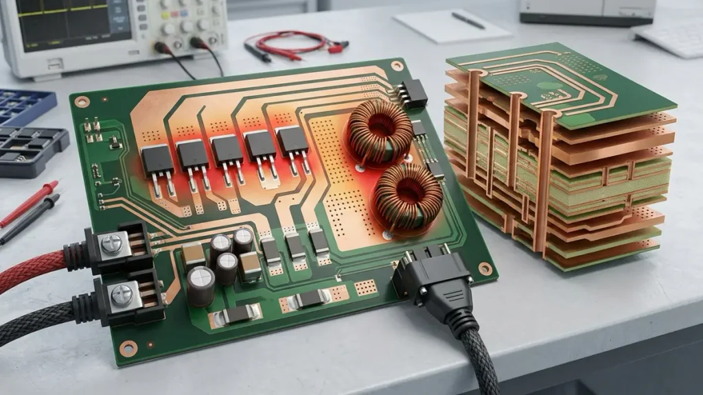
High-current PCB construction and thermal management for 48V automotive power electronics.
A 48V rating alone does not determine the PCB construction. Current, power dissipation, transient conditions, insulation requirements, operating temperature, and mechanical constraints all influence the material selection and board layout.
For procurement teams, the important question is whether the manufacturer can translate the approved design data into a consistent PCB and assembly process.
2.1 Copper Thickness and High-Current Routing
Current capacity is one of the primary considerations in 48V power electronics.
The required copper thickness and conductor geometry depend on:
- Continuous and peak operating current
- Permitted temperature rise
- Copper weight and finished copper thickness
- External or internal copper layer location
- Trace width and copper-plane area
- Ambient temperature and airflow
- PCB stack-up and enclosure conditions
Increasing copper thickness can reduce conductor resistance, but it is not a substitute for proper thermal and electrical design. Narrow neck-downs, undersized pads, insufficient via capacity, and poorly designed connector interfaces can still create local heating.
For multilayer boards, power distribution may use dedicated copper planes or parallel copper paths. Where current transfers between layers, the number, diameter, and arrangement of vias must be evaluated against the expected current and thermal conditions.
PCBKR can review specified copper thickness, layer structure, trace geometry, via requirements, and fabrication constraints against the supplied design files. For projects with demanding current requirements, see our heavy copper PCB manufacturing capabilities.
2.2 PCB Material and Stack-Up Selection
Material selection should be based on the actual operating environment rather than voltage alone.
Key considerations include:
| Design factor | Engineering consideration |
|---|---|
| Base material | FR-4 or a specified high-temperature material, subject to operating conditions |
| Layer count | Determined by power routing, control circuits, grounding, and signal requirements |
| Finished board thickness | Must satisfy electrical, mechanical, and enclosure constraints |
| Copper thickness | Selected according to current, temperature rise, and routing space |
| Dielectric spacing | Defined by working voltage, transient conditions, material properties, and applicable safety requirements |
| Thermal performance | Consider copper distribution, component losses, heat spreading, and cooling conditions |
| Surface finish | Selected according to component, soldering, and customer requirements |
The working voltage and nominal 48V supply should not be treated as the only basis for insulation design. Transient voltage, pollution conditions, altitude, material properties, and the applicable product standard may also affect clearance and creepage requirements.
A manufacturer should work from the customer’s approved stack-up and electrical requirements rather than assigning a generic board construction to every 48V project.
2.3 Thermal Management Around Power Components
Power MOSFETs, inductors, shunt resistors, rectifiers, and connectors can generate concentrated heat. Excessive temperature may affect component life, solder-joint reliability, and long-term electrical performance.
PCB thermal design should consider:
- Copper area connected to power devices
- Thermal vias beneath or around heat-generating components
- Component spacing and local heat concentration
- Heat transfer to metal housings or heat sinks
- Airflow and enclosure limitations
- Solder-joint design for large or high-mass components
Thermal vias and copper planes can help spread heat, but the final result depends on the complete assembly and cooling arrangement. A board that passes a basic electrical test may still require thermal validation under representative operating loads.
2.4 Connectors, Terminals, and Busbar Interfaces
High-current interfaces deserve particular attention during PCB fabrication and PCBA assembly.
The design review should check:
- Connector current rating and terminal compatibility
- Pad dimensions and copper reinforcement
- Through-hole or press-fit interface requirements
- Mechanical retention and mounting-hole positions
- Soldering requirements for large terminals
- Busbar-to-PCB connection geometry
- Clearance between power terminals and control circuits
If the design uses a copper busbar, the mechanical interface, contact resistance, fastening method, and thermal expansion should be considered together. The PCB manufacturer should receive the relevant mechanical drawings and assembly requirements before production.
3. Electrical Protection and Signal Integrity in 48V PCBA
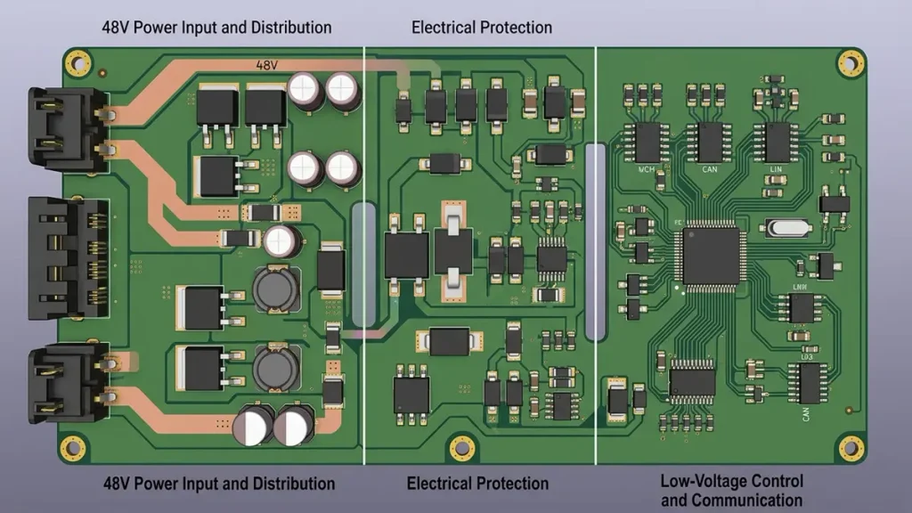
48V automotive PCBA integrating power protection, voltage regulation, and CAN/LIN communication circuits.
48V automotive electronics must operate in an electrically demanding environment. Protection and communication requirements need to be considered during circuit design, PCB layout, component selection, and assembly verification.
3.1 Overcurrent, Short-Circuit, and Reverse-Polarity Protection
Depending on the application, a 48V power board may incorporate:
- Fuse or electronic fuse protection
- High-side and low-side power switches
- Current-sensing circuits
- Reverse-polarity protection
- Reverse-current blocking
- Overvoltage and undervoltage monitoring
- Short-circuit detection
- Transient suppression components
These functions are determined by the electrical architecture and system-level safety requirements. PCB fabrication and assembly must preserve the specified component placement, polarity, spacing, soldering quality, and electrical connections.
A PCBA supplier should not assume that the presence of a protection component automatically proves that the assembled board meets the required fault-handling performance. Functional verification must follow the test limits and procedures defined by the customer.
3.2 EMI and EMC Considerations
Switching power converters and high-current switching circuits can generate electromagnetic interference. Poor PCB layout may increase conducted or radiated emissions and affect nearby control or communication circuits.
Important layout considerations include:
- Minimizing high-frequency switching-current loops
- Maintaining appropriate separation between power and sensitive signal paths
- Providing suitable ground-return paths
- Controlling switching-node copper area
- Placing decoupling and filtering components close to their relevant devices
- Managing common-mode and differential-mode noise paths
The PCB manufacturer must maintain the approved copper pattern, layer registration, impedance requirements where specified, and assembly configuration. EMC compliance, however, is a system-level result and cannot be guaranteed by PCB fabrication or visual inspection alone.
3.3 CAN and LIN Communication Protection
Many automotive power distribution and control boards combine power electronics with communication interfaces such as CAN, CAN FD, or LIN.
The design must account for possible electrical faults, ground shifts, transient conditions, and interference between power switching and communication circuits. Transceiver selection and protection architecture are circuit-design responsibilities, while PCB layout and assembly quality help preserve the intended electrical performance.
Texas Instruments identifies safe 48V power distribution, voltage conversion, protection of lower-voltage I/O circuits, and CAN/LIN communication integrity as key design challenges in 48V automotive systems. These considerations should be reflected in the customer’s design and verification plan.
Technical reference: TI – 4 Critical Design Challenges for 48V Systems.
4. 48V Automotive PCBA Assembly Process
A reliable assembly process must accommodate both power components and low-level control electronics. Depending on the design, a 48V automotive PCBA may combine surface-mount technology (SMT), through-hole technology (THT), and specialized soldering operations.
4.1 SMT Assembly
SMT is commonly used for controllers, resistors, capacitors, protection devices, MOSFETs, and other surface-mounted components.
Important process controls include:
- Solder paste printing and inspection
- Component placement accuracy
- Reflow profile control
- Polarity and orientation verification
- Solder-joint inspection
- Component and PCB revision control
Power components with exposed thermal pads or large copper connections may require particular attention to solder paste design and thermal-process consistency.
4.2 Through-Hole Assembly
Large connectors, power terminals, transformers, inductors, and mechanically reinforced components may require through-hole assembly.
The assembly process should account for:
- Pin alignment and insertion depth
- Solder fill and joint formation
- Thermal requirements for high-mass terminals
- Mechanical support during handling
- Clearance around adjacent components
- Customer-defined soldering and inspection criteria
For mixed SMT and THT boards, the assembly sequence must be planned to avoid damaging previously installed components or compromising solder-joint quality.
4.3 Component Sourcing and BOM Control
Component sourcing is a major procurement consideration for automotive electronics. A low-cost substitute may have different electrical ratings, package dimensions, thermal characteristics, or qualification status.
Before production, buyers should confirm:
- Manufacturer part number (MPN) for each critical component
- Approved manufacturer and supplier requirements
- Whether alternative components are permitted
- Component lifecycle and availability
- Moisture sensitivity and storage requirements
- Lot traceability requirements
- Customer approval procedures for substitutions
PCBKR can work from customer-supplied BOMs and agreed sourcing instructions. Any proposed substitution should be reviewed and approved according to the customer’s change-control process before it is used in production.
5. Quality Inspection and Testing for Automotive PCBA
Inspection and testing should be selected according to the product’s risks and acceptance criteria. No single inspection method can verify every aspect of a 48V automotive PCBA.
| Inspection or test | What it checks | Typical purpose |
|---|---|---|
| Visual inspection | Component condition, polarity, soldering, workmanship | Detect visible assembly defects |
| 3D AOI | Component presence, position, orientation, solder-related visual defects | Inspect SMT assembly |
| X-ray inspection | Hidden solder joints, such as BGA connections | Evaluate joints not visible from the surface |
| Flying probe or electrical test | Electrical connectivity and specified net conditions | Identify open or short circuits |
| Power-on test | Basic electrical behavior under defined conditions | Verify specified power-up functions |
| Functional test | Board operation against a customer-defined test procedure | Check application-specific functions |
| Thermal test | Temperature behavior under defined operating conditions | Evaluate thermal performance |
| Reliability testing | Performance under specified environmental or endurance conditions | Support product qualification |
PCBKR’s stated inspection resources include 3D AOI, X-ray inspection, four-wire Kelvin flying-probe testing, and VNA measurement capability up to 70 GHz. The appropriate equipment and test method depend on the board design and the customer’s inspection plan. VNA capability, for example, is relevant to specified high-frequency electrical measurements; it is not a routine substitute for functional testing of a 48V power board.
5.1 Electrical Testing Is Not the Same as Functional Testing
A board may pass continuity testing while still containing an incorrect component value, a wrong component orientation, or a functional issue.
For this reason, buyers should define the required test scope before production. A functional test may need a dedicated fixture, test software, power supply, load, communication interface, or customer-provided test procedure.
For high-current boards, the test plan may also need to define current limits, load conditions, temperature monitoring, and the permitted voltage drop across specified power paths.
5.2 Traceability and Production Records
Automotive supply chains often require documented control of materials, production batches, inspection results, and engineering changes.
Depending on customer requirements, the production record may include:
- PCB and PCBA part numbers
- Gerber, BOM, and assembly drawing revisions
- Component manufacturer and lot information
- Production batch identification
- Inspection and test records
- Nonconformance and corrective-action records
- Approved engineering changes
The exact traceability depth should be agreed before quotation. Buyers should confirm which records are available, how long they are retained, and whether serial-number-level traceability is required.
6. Automotive Quality Requirements: IATF 16949, AEC-Q, and ISO 26262
These standards and qualification systems address different parts of the automotive supply chain. They should not be treated as interchangeable.
| Standard or qualification | Main scope | What buyers should verify |
|---|---|---|
| IATF 16949 | Automotive quality management system requirements | Whether the supplier’s certification is valid and covers the relevant manufacturing site and scope |
| ISO 9001 | General quality management system | Certificate validity, issuing body, site, and scope |
| AEC-Q | Qualification requirements for specified electronic components | Whether the actual components meet the required qualification grade |
| ISO 26262 | Functional safety of road vehicles’ electrical and electronic systems | Product and development-process responsibilities defined by the project |
IATF 16949 certification is a supplier quality-system matter. AEC-Q qualification applies to components, not automatically to the complete PCBA. ISO 26262 addresses functional safety and does not become a product certification simply because a PCB or PCBA supplier holds a quality management certificate.
Before placing an order, procurement and quality teams should request the relevant certificate and verify its validity, manufacturing location, and scope. They should also confirm any OEM-specific requirements, customer audits, process approvals, and product-level validation obligations.
PCBKR can provide applicable company and quality documentation for customer review. Certification applicability should be confirmed against the actual site, process, and project scope rather than assumed from a general company statement.
7. Turnkey, Consignment, and Hybrid PCBA Manufacturing
The right procurement model depends on the buyer’s sourcing strategy, component control requirements, and internal engineering resources.
| Manufacturing model | Material responsibility | Suitable situation |
|---|---|---|
| Turnkey PCBA | Supplier sources PCB and agreed components and performs assembly | Buyers seeking a consolidated manufacturing and sourcing arrangement |
| Consignment assembly | Customer supplies the PCB and/or components according to the agreed scope | Buyers who need direct control over critical components |
| Hybrid sourcing | Customer and supplier share material sourcing responsibilities | Projects with a combination of controlled and supplier-sourced components |
For 48V automotive projects, the procurement agreement should clearly identify who is responsible for component selection, sourcing approval, substitutions, incoming inspection, material traceability, and shortages.
A turnkey quotation should not be compared with a consignment quotation based on assembly price alone. The material scope, approved manufacturers, test coverage, packaging, documentation, and delivery responsibility must also be compared.
PCBKR supports PCB manufacturing and PCBA assembly arrangements based on customer requirements. The specific turnkey, consignment, or hybrid scope should be confirmed during the RFQ review.
8. How to Control Cost and Lead Time for 48V Automotive PCBA
The cost of a 48V automotive PCBA is influenced by more than PCB size and component count.
8.1 Main Cost Drivers
The most important cost factors generally include:
- PCB construction: Layer count, board dimensions, copper thickness, material, finished thickness, and fabrication tolerances.
- Component selection: Power semiconductors, connectors, inductors, specialized ICs, and component availability.
- Assembly complexity: SMT density, THT quantity, large thermal pads, fine-pitch packages, and mixed-technology requirements.
- Testing requirements: AOI, X-ray, electrical testing, functional fixtures, and customer-specific test procedures.
- Traceability and documentation: Material records, batch identification, inspection reports, and quality documentation.
- Order quantity: Prototype, pilot, small-batch, and production volumes have different setup and material-planning costs.
The lowest initial quotation may not provide the lowest total procurement cost if it excludes required inspection, traceability, or functional testing.
8.2 Factors Affecting Production Lead Time
Lead time depends on the complete order scope, including:
- PCB fabrication complexity
- Component availability and procurement lead time
- Customer approval of BOM alternatives
- Special connector or mechanical-part sourcing
- Assembly process and test-fixture preparation
- First-article inspection and approval
- Required documentation and packaging
For a more reliable quotation, buyers should provide complete design data and identify any long-lead or customer-controlled components at the beginning of the project.
9. How to Request a 48V Automotive PCBA Manufacturing Quote
A complete RFQ package helps the manufacturer evaluate fabrication feasibility, material sourcing, assembly complexity, and testing requirements. It also reduces the risk of quotation revisions caused by missing technical information.
For an accurate quotation, prepare the following files and specifications:
| RFQ information | Details to provide |
|---|---|
| Gerber or ODB++ files | PCB fabrication data and layer information |
| PCB stack-up | Layer count, material, copper thickness, and finished board thickness |
| BOM | MPN, manufacturer, quantity, and approved alternatives |
| Pick-and-place file | Component coordinates, rotation, and reference designators |
| Assembly drawings | Component orientation, polarity, mechanical details, and special instructions |
| Electrical requirements | Operating voltage, continuous and peak current, power limits, and protection requirements |
| Testing requirements | AOI, X-ray, electrical, functional, thermal, and other specified tests |
| Order information | Prototype quantity, pilot quantity, forecast, and production volume |
| Delivery requirements | Target delivery date, packaging, labeling, and shipping destination |
| Quality requirements | Applicable standards, traceability, inspection records, and customer-specific requirements |
If the design includes busbars, high-current terminals, heat sinks, or enclosure interfaces, provide the relevant mechanical drawings as well.
PCBKR reviews the submitted files and project requirements to assess PCB manufacturing, component sourcing, PCBA assembly, and inspection scope. If the design requires clarification, the engineering and quotation teams can identify the missing information before order confirmation.
Request a quotation: Email your Gerber files, BOM, assembly drawings, and project requirements to sales@pcbkr.com.
10. Frequently Asked Questions: Choosing a 48V Automotive PCBA Supplier
How do I choose a reliable 48V automotive PCBA manufacturer?
Evaluate the supplier’s PCB fabrication capability, SMT and THT assembly processes, experience with power-component assembly, inspection equipment, material traceability, and quality documentation. Ask for evidence of the actual manufacturing site’s certifications and confirm whether the supplier can meet your required copper thickness, board construction, component sourcing, and testing scope. A supplier should review your Gerber files and BOM before confirming feasibility and quotation.
Can a PCBA manufacturer provide turnkey 48V automotive PCB assembly?
Yes. A turnkey supplier can manage PCB fabrication, agreed component sourcing, PCB assembly, and specified inspection or testing within one manufacturing arrangement. However, buyers should define the exact sourcing responsibility, approved component manufacturers, substitution approval process, and test scope. Some projects require customer-controlled components or a hybrid sourcing model rather than full turnkey procurement.
What files are required to get a 48V automotive PCBA quotation?
A typical RFQ package includes Gerber or ODB++ files, PCB stack-up, BOM with manufacturer part numbers, Pick-and-Place data, assembly drawings, order quantity, and delivery requirements. For power electronics, also provide continuous and peak current, operating conditions, connector or busbar drawings, thermal requirements, and the requested inspection and functional test procedures. Complete information helps prevent quotation delays and scope misunderstandings.
Does an automotive PCBA supplier need IATF 16949 certification?
The requirement depends on the customer’s supply-chain rules, product application, and contractual quality requirements. Many automotive customers require suppliers within their production supply chain to meet specific automotive quality-system expectations, and some require IATF 16949 certification. Buyers should verify the supplier’s certificate, manufacturing site, and scope, as well as any OEM-specific approval requirements. IATF 16949 does not by itself certify an individual PCBA as functionally safe or automotive-qualified.
What testing should be specified when ordering 48V automotive PCBA?
The test plan should reflect the product’s electrical and operating risks. Common requirements include visual inspection, AOI, X-ray for applicable hidden solder joints, electrical continuity testing, and customer-defined power-on or functional testing. High-current products may also require load testing and thermal evaluation under specified conditions. Buyers should provide acceptance limits, test procedures, fixtures, and documentation requirements before production so the supplier can quote the correct inspection scope.
Discuss Your 48V Automotive PCBA Project with PCBKR
Choosing a 48V automotive PCBA supplier requires a clear understanding of PCB construction, power-component assembly, electrical protection, thermal management, material control, and inspection requirements. The manufacturing process should be matched to the approved design and the customer’s quality expectations—not based on a generic 48V specification.
Shenzhen Hongda Circuit Technology Co., Ltd. provides PCB manufacturing and PCBA assembly services for overseas OEM customers, covering prototype, small-batch, and production requirements subject to project review.
Send your design files and procurement requirements to:
- Company: Shenzhen Hongda Circuit Technology Co., Ltd.
- Email: sales@pcbkr.com
- Website: https://www.pcbkr.com/
Submit your Gerber files, BOM, target quantity, and testing requirements to request a manufacturing review and quotation.
About Author
David Chen LinkedIn Profile
David Chen is a Senior RF/PCB Process Engineer at Shenzhen Hongda Circuit Technology Co., Ltd., with over 12 years of experience in high-frequency PCB fabrication, impedance-controlled stack-up design, and Rogers/PTFE laminate processing. He also boasts an extensive professional background in PCBA manufacturing, PCBA testing, and PCBA optimization, with specialized expertise in high-precision PCBA fault analysis and rigorous PCBA reliability testing. The author has worked with high-layer-count server PCB fabrication, ultra-low-loss backplane stackups, and thermo-mechanical reliability optimization for AI infrastructure projects involving 112G and 224G PAM4 architectures. Skilled in complex circuit design and cutting-edge advanced PCB manufacturing processes, he delivers solutions that elevate product durability and performance across industrial applications. His technical articles focusing on PCBA manufacturing workflows and testing methodologies are widely cited by industry peers and technical platforms, and have gained attention and recognition from industry colleagues.