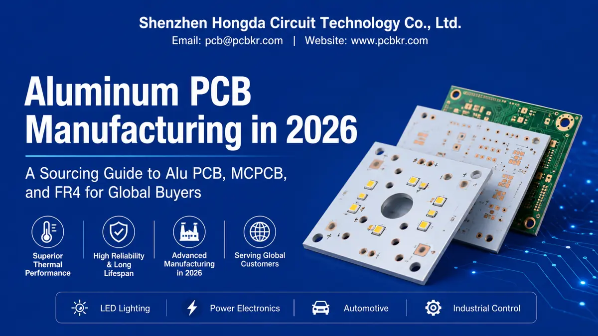
Aluminum PCB Manufacturing Sourcing Guide: Alu PCB, MCPCB & FR4 for Global Buyers
When a procurement engineer types “aluminum pcb manufacturer” into Google at 11 p.m.
before a supplier shortlist deadline, they are not looking for marketing copy. They want to
know what the board actually is, how it is built, what it costs against FR4, and which factory
can be trusted to hit a thermal spec without a second sample round. This guide is written
for that moment — and for the design engineers, sourcing managers, and OEM buyers who
arrive at it from a dozen different search queries about aluminum-based circuit boards.
At Shenzhen Hongda Circuit Technology Co., Ltd., we manufacture aluminum PCBs,
aluminium PCBs, and metal-core boards (MCPCB) for LED lighting, power electronics, and
automotive customers across North America, Europe, and Southeast Asia. Everything
below reflects both current 2026 process capability and the questions our sales engineers
field every week from new accounts.
What Is an Aluminum PCB? Understanding Alu PCB and Aluminium PCB Terminology
An aluminum PCB — also written as alu PCB or aluminium PCB depending on the buyer’s
region — is a metal-core printed circuit board built on an aluminum alloy base instead of
the woven fiberglass used in FR4. The metal core does one job better than any laminate: it
pulls heat away from hot components and spreads it across a wider surface before it ever
reaches a heatsink.
Despite the spelling variations, aluminum PCB, alu PCB, and aluminium PCB refer to the
same product family. Buyers searching any of these terms are typically evaluating the same
shortlist of suppliers, so a factory’s technical documentation needs to speak all three
dialects clearly.
The Three-Layer Structure of an Aluminum Circuit Board
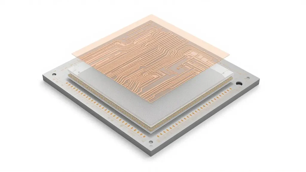
3D Exploded View of Alu PCB Structure
Every aluminum circuit board is built from three bonded layers:
1.Copper circuit layer — the conductive layer where traces, pads, and components sit, typically 35µm to 105µm depending on current-carrying requirements.
2.Dielectric layer — a thin, thermally conductive insulating film that must do two jobs
at once: block electrical current from reaching the metal base while still letting heat
pass through efficiently.
3.Aluminum base layer — the structural and thermal backbone, usually 60–85% of
total board thickness, that spreads heat laterally before it dissipates into a heatsink or
enclosure.
The dielectric layer is the real engineering challenge in this stack. A layer that insulates well
but conducts heat poorly defeats the purpose of choosing an aluminum board in the first
place, which is why dielectric formulation is one of the areas where manufacturers
differentiate most.
Aluminum PCB Board vs Aluminum Box PCB: Reading Buyer Search Intent
Two related terms show up constantly in supplier searches: aluminum PCB board (the flat,
single- or double-layer substrate itself) and aluminum box PCB, which usually refers to an
enclosed or housing-integrated aluminum assembly used in outdoor lighting, industrial
controls, or automotive modules where the metal base doubles as part of the mechanical
housing. A capable aluminum PCB manufacturer should be able to quote both without
treating them as separate product lines, since the underlying lamination and drilling
process is largely shared.
How Aluminum PCB Boards Are Made: A 2026 Manufacturing Walkthrough
The process an aluminum PCB manufacturer runs today looks different from what the
industry used five years ago, mainly because thermal-via performance and lamination
consistency have become the two biggest differentiators between suppliers.
Substrate Preparation and Precision Cutting
Production starts with precision-cut, cleaned aluminum sheet stock. Surface cleaning
quality at this stage determines dielectric adhesion later, so factories running tight
tolerance work typically use industrial-grade degreasing lines rather than manual wipe
downs, since inconsistent cleaning is one of the more common causes of delamination
during thermal cycling tests.
Dielectric Bonding and Laser Via Drilling — Where 2026 Process Advances Matter
Bonding the dielectric layer to the aluminum core now runs on automated roller lamination
systems with vision-guided alignment, which keeps thermal-conductivity variation
between panels far tighter than manual bonding ever could. On the drilling side,
controlled-depth and laser drilling have largely replaced older mechanical methods for
thermal vias, because mechanical drilling tends to leave burrs on the aluminum core that
create voids once plated. Many fabricators can now support via-in-pad filling with
planarization at densities suitable for high-power LED and power-module layouts, and pair
that with conductive fill materials engineered for lower thermal expansion mismatch
against the copper and aluminum layers around them.
Copper Circuit Layer Formation and Surface Finishing
Once the core and dielectric are bonded, copper foil is etched into the circuit pattern using
standard chemical etching, followed by surface finishing — ENIG or OSP are the two most
common choices — selected to preserve solderability on any capped or filled vias. Aspect
ratios below roughly 10:1 remain the safe target for reliable electrodeposition on plated vias;
going beyond that without a validated process tends to introduce resistance-raising voids.
Before committing to a technology, most buyers want the numbers side by side rather than
a sales pitch. Here is how aluminum PCB, standard FR4, and copper-based MCPCB
typically compare across the criteria that matter most in an initial budget review.
| Criteria | Aluminum PCB | FR4 | Copper MCPCB |
|---|---|---|---|
| Relative cost | 20-30% higher than FR4 | Lowest cost, mature supply chain | Highest — premium copper core |
| Thermal conductivity | Aluminum core ~180-200 W/m·K; dielectric layer ~2-10 W/m·K | ~0.3 W/m·K; relies on copper trace spreading | 380-400+ W/m·K |
| Weight | Aluminum density ~2.7 g/cm³ — light for its thermal capacity | Lightest per board, but weaker at high temperature | Copper density ~8.9 g/cm³ — noticeably heavier |
| Tg / heat resistance | Stable well past 150°C with a properly matched dielectric | Typically softens above ~130°C | Generally exceeds FR4, dependent on dielectric choice |
| Layer count / complexity | Usually single- or double-layer; not suited to dense multilayer routing | Handles multilayer, fine-pitch, high-density designs easily | Similar single-layer bias to aluminum, reserved for the highest-power designs |
Reading the Table: What It Means for Sourcing Decisions
If the design’s problem is heat — LED arrays, power converters, motor drivers — an
aluminum circuit board earns its cost premium quickly by cutting the need for oversized
heatsinks or forced-air cooling. If the design’s problem is routing density or layer count,
FR4 remains the more practical and economical route. Copper MCPCB sits above both,
reserved for the smaller subset of designs where even aluminum’s thermal ceiling isn’t
enough and budget allows for it.
2026 Manufacturing Technology Advances at Shenzhen Hongda Circuit Technology
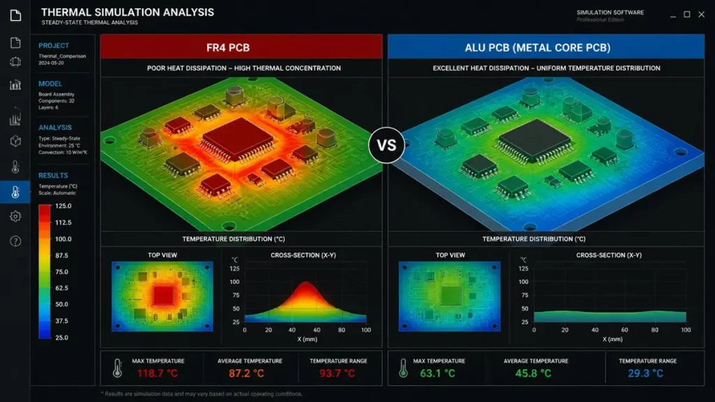
Alu PCB vs FR4 Thermal Simulation Analysis
Buyers evaluating any aluminum PCB manufacturer in 2026 should expect a few specific
capabilities to be standard, not premium add-ons:
1. Laser and controlled-depth via drilling on aluminum box PCB and standard
aluminum PCB board designs, avoiding the burring that mechanical drilling causes on
metal cores.
2. Vision-guided automated lamination, which measurably tightens thermal
conductivity consistency panel to panel compared with manual bonding lines.
3. Thermal-electrical co-simulation during DFM review, modeling how copper trace
current density interacts with heat generation before tooling is cut — this catches
thermal bottlenecks that a static thermal spec sheet alone would miss.
4. Closed-loop aluminum reclamation, reprocessing scrap substrate back into usable
material, which has become a meaningful sourcing consideration for OEM customers
with their own sustainability reporting requirements.
We build these into standard DFM review rather than treating them as a premium tier,
because most quality escapes we see from other factories trace back to skipping one of
these steps to save a production cycle.
Prototyping: Can Small PCB Milling Machines Cut Aluminum?
Engineers prototyping in-house sometimes ask whether a desktop or small-format PCB
milling machine can process aluminum PCB stock directly. In practice, most hobbyist and
light-duty milling machines are built for FR4 and struggle with aluminum cores — the
metal dulls standard bits quickly and the heat generated during milling can distort thin
dielectric layers. For anything beyond a single test coupon, sending the design to a
manufacturer running proper laser or CNC-controlled drilling avoids both the tool wear
and the inconsistent hole quality that comes from adapting FR4-rated equipment to metal
core stock.
How to Solder Aluminum PCB: Assembly Considerations Buyers Should Flag Early
Aluminum PCBs solder using the same reflow and wave processes as FR4, but the thermal
mass of the metal core changes the profile. The aluminum base absorbs heat faster than a
fiberglass laminate, so reflow profiles typically need a longer, more controlled ramp to bring
the whole assembly — not just the surface pads — up to soldering temperature evenly.
Skipping this adjustment is one of the more common causes of insufficient wetting or
voiding reported by assembly teams new to metal-core boards. Buyers sourcing both the
bare board and assembly from the same supplier should confirm the factory has
documented reflow profiles specific to aluminum stock, rather than reusing an FR4 profile
by default.
When to Choose an Aluminum PCB Manufacturer: Application Fit
1. LED lighting and horticultural lighting — high junction temperatures and long
operating hours make thermal spreading through an aluminum base a near-default
choice.
2.Power modules and converters — switching components generate concentrated heat
that benefits directly from a metal core’s lateral spreading.
3. Automotive and EV electronics — under-hood and battery-adjacent modules
combine thermal load with vibration and temperature cycling, both of which
aluminum’s mechanical stability handles well.
4.Outdoor and industrial enclosures — this is where aluminum box PCB designs are
common, since the metal base can double as part of the housing’s structural and
thermal path.
Why Buyers Choose Shenzhen Hongda Circuit Technology as Their Aluminum PCB Manufacturer
We run aluminum PCB, alu PCB, and metal core PCB production lines alongside standard
FR4 capability, which means a single sourcing conversation can cover a full board family
rather than juggling separate suppliers for the metal-core and standard boards on the same
product line. Our DFM review includes thermal simulation before tooling, documented
reflow profiles for metal-core assembly, and via-in-pad capability for the higher-density
aluminum box PCB designs increasingly common in outdoor and automotive housings. For
buyers building a shortlist, we typically start with a technical questionnaire covering
thermal load, layer count, and Tg requirements rather than a generic quote — it shortens
the sampling cycle on both sides.
Frequently Asked Questions for Buyers Sourcing an Aluminum PCB Manufacturer
How do I verify an aluminum PCB manufacturer’s real production capability before sending an RFQ?
Ask for documented thermal conductivity test reports (not just datasheet
values), photos or video of the actual lamination and drilling line, and a list of aspect ratios and via densities the factory has run in production — not just in a lab trial. A supplier that can’t produce this on request usually outsources the metal-core process to a subcontractor.
What’s a realistic price difference between an aluminum PCB and an equivalent FR4 board?
Expect roughly 20–30% higher cost for aluminum versus FR4 at comparable size and layer count, driven mainly by substrate material and slower lamination cycles. Copper MCPCB runs higher still. Get quotes in the same volume tier, since aluminum pricing tends to compress more than FR4 at higher order quantities.
Can one factory handle both aluminum PCB fabrication and assembly, or should these be split across two suppliers?
Either works, but if splitting suppliers, insist that the assembly partner has a documented reflow profile for metal-core boards before committing volume. Aluminum’s thermal mass changes reflow behavior enough that reusing an FR4 profile is a common source of early-batch soldering defects.
What lead time should I expect for a first aluminum PCB prototype run compared to FR4?
Aluminum prototypes typically add several days to a comparable FR4 turnaround because of the extra lamination and via-fill steps. Buyers on tight timelines should flag thermal requirements at the RFQ stage rather than after DFM review, since late thermal changes often mean relaminating rather than a simple respin.
How do I know if my design actually needs an aluminum PCB instead of FR4 with better heatsinking?
If component junction temperature specs are already tight with a
reasonable heatsink and airflow assumption on FR4, aluminum may be unnecessary cost. Aluminum earns its premium when the heat source is concentrated, the enclosure is sealed or has limited airflow, or the design is size-constrained enough that adding a larger external heatsink isn’t practical.
About Author
David Chen https://www.linkedin.com/in/pcbcoming
David Chen boasts an extensive professional background in PCBA manufacturing, PCBA testing, and PCBA optimization, with specialized expertise in high-precision PCBA fault analysis and rigorous PCBA reliability testing. The author has worked with high-layer-count server PCB fabrication, ultra-low-loss backplane stackups, and thermo-mechanical reliability optimization for AI infrastructure projects involving 112G and 224G PAM4 architectures. Skilled in complex circuit design and cutting-edge advanced PCB manufacturing processes, he delivers solutions that elevate product durability and performance across industrial applications. His technical articles focusing on PCBA manufacturing workflows and testing methodologies are widely cited by industry peers, research institutions, and technical platforms, solidifying his reputation as a recognized technical authority in the global circuit board manufacturing sector.