FR4 PCB Glass Transition Temperature: What Tg Should You Choose?
For most FR4 PCBs, the right glass transition temperature (Tg) depends on actual operating temperature, thermal cycling, assembly profile, layer count, copper construction, and reliability requirements—not simply whether the laminate is labeled “standard Tg” or “high Tg.” The correct choice is the Tg and material system qualified for the complete thermal environment.
What Is FR4 PCB Glass Transition Temperature?
FR4 PCB glass transition temperature (Tg) is the temperature region where the cured resin system changes from a relatively rigid, glassy state toward a softer, more mobile state. It is an important laminate‑selection parameter because resin behavior, dimensional stability, and thermal expansion characteristics change around this transition.
The term FR4 does not describe one single laminate chemistry with one fixed Tg. Different resin systems, glass styles, resin contents, curing systems, manufacturers, and material grades can produce substantially different Tg values.
For procurement engineers, this distinction is important.
A PCB drawing that simply states:
“FR‑4, Tg ≥150°C”
may still leave several engineering questions unanswered:
- Which laminate manufacturer?
- Which exact material grade?
- Was Tg measured by DSC, TMA, or DMA?
- What is the Z‑axis CTE?
- What are the T260 and T288 values?
- What is the decomposition temperature (Td)?
- What reflow profile will the board experience?
- How many thermal cycles are expected?
- Is the PCB a two‑layer board or a 20+ layer HDI construction?
- What copper thickness and via structure are involved?
A robust material specification therefore treats Tg as one part of a thermal‑reliability system rather than as a standalone purchasing number.
What Does FR4 Tg Mean for Material Selection?
The practical meaning of Tg is that the resin system’s mechanical and thermal behavior changes around a defined transition region.
Below Tg, the cured resin generally maintains a higher level of rigidity. As temperature approaches and passes through the transition, molecular mobility increases and the resin becomes less rigid.
This matters because multilayer PCBs experience dimensional changes during:
- lamination,
- solder reflow,
- wave soldering,
- thermal cycling,
- powered operation,
- environmental qualification,
- repair or rework.
The effect becomes more important as board construction becomes more complex.
For example, a simple four‑layer industrial controller may experience a very different thermal strain environment from a 24‑layer HDI board containing stacked microvias, multiple copper weights, large BGA fields, and repeated lead‑free reflow.
Why Does FR4 Tg Vary by Laminate Grade?
FR4 Tg varies because “FR4” is a material classification rather than a single resin formulation.
A laminate manufacturer may offer several FR4 families with different:
- resin chemistry,
- Tg,
- Td,
- Z‑axis CTE,
- dielectric properties,
- modulus,
- moisture resistance,
- thermal decomposition behavior,
- copper adhesion,
- thermal cycling performance.
Two materials can both be marketed as FR4 while having very different thermal‑reliability characteristics.
That is why an experienced PCB manufacturer should not approve material only from the generic term “FR4.”
The exact material grade and its current datasheet should be linked to the PCB fabrication package.
What Is Standard Tg FR4?
Standard Tg FR4 generally refers to conventional FR4 laminate systems with Tg values commonly around the low‑to‑mid 130°C range, although the exact classification varies by supplier and test method.
A typical market description may place conventional FR4 around approximately 130–140°C Tg, but this should never be treated as a universal material specification.
The actual value must come from the laminate manufacturer’s datasheet and stated test method.
What Temperature Range Is Typical for Standard Tg FR4?
Many conventional FR4 materials fall approximately within the 130–150°C range depending on formulation and measurement method.
However, procurement teams should be careful with labels such as:
- Standard Tg
- Mid Tg
- Medium Tg
- High Tg
These commercial categories are not sufficiently precise for a controlled engineering specification.
For example, one supplier may describe a material around 150°C as medium Tg, while another supplier may use a different classification.
The more reliable approach is to specify the minimum required Tg plus the test method and material grade.
A purchasing specification such as:
FR‑4, Tg ≥170°C by DSC
is more useful than:
High‑Tg FR4
because the second statement leaves the acceptance criterion open to interpretation.
When Is Standard Tg FR4 Enough?
Standard Tg FR4 can be an appropriate candidate when the application has:
- moderate operating temperatures,
- limited thermal cycling,
- conventional multilayer construction,
- controlled soldering exposure,
- moderate copper thickness,
- no unusually severe thermal‑reliability requirement.
Typical examples can include:
- general industrial control boards,
- consumer electronics,
- low‑to‑moderate temperature interfaces,
- conventional power‑management electronics,
- non‑critical embedded controllers.
However, “standard Tg is enough” should be decided from the complete thermal profile.
A board that operates at only 70°C may still require a higher‑performance laminate if it undergoes repeated thermal excursions, multiple assembly cycles, high copper stress, thick multilayer construction, or demanding reliability qualification.
What Is High Tg FR4?
High Tg FR4 uses a resin system engineered to provide a higher glass transition temperature than conventional FR4, often with Tg values around 170°C or above depending on the specific material family and measurement method.
High‑Tg FR4 is commonly considered when the PCB must tolerate more demanding thermal exposure or when the construction creates greater thermal‑mechanical stress.
Applications can include:
- automotive electronics,
- industrial power electronics,
- high‑layer‑count PCBs,
- HDI structures,
- repeated lead‑free reflow,
- high‑reliability control systems,
- equipment exposed to substantial temperature cycling.
But a higher Tg alone does not automatically make a PCB more reliable.
When Should You Choose High Tg FR4?
High Tg becomes a stronger candidate when several thermal stress factors occur simultaneously.
For example: Higher operating temperature + repeated thermal cycling + complex multilayer construction
creates a stronger argument for a high‑performance laminate than any one factor alone.
Consider a 20‑layer industrial control board.
The PCB may experience:
- assembly heating,
- multiple reflow cycles,
- component self‑heating,
- enclosure temperature rise,
- repeated power‑on/off cycles,
- environmental temperature cycling.
During each temperature excursion, the PCB expands and contracts.
The engineering question is therefore not simply:
“Is the Tg high enough?”
It is:
“Can the complete laminate system maintain the required dimensional and interconnect reliability through the expected thermal history?”
That distinction leads to better material selection.
Is High Tg FR4 Always Better?
No.
A high‑Tg laminate may provide greater thermal margin for a particular design, but it can also increase material cost and may provide performance that the application does not actually require.
More importantly, high Tg does not eliminate other reliability mechanisms.
A high‑Tg material can still experience:
- excessive Z‑axis expansion,
- delamination,
- barrel fatigue,
- microvia reliability problems,
- CAF risk,
- resin starvation,
- moisture‑related failures,
- dimensional instability,
- soldering defects.
For high‑reliability designs, Tg should therefore be evaluated together with Td, Z‑axis CTE, T260/T288, modulus, moisture behavior, thermal cycling and PCB construction.
What Is the Difference Between Standard Tg and High Tg FR4?
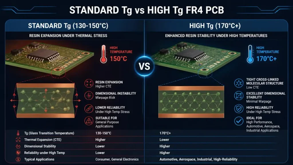
Comparison Infographic: Standard Tg (130-150°C) vs High Tg (170°C+) FR4 PCB
The primary difference is the resin system’s transition temperature and associated thermal behavior, but the engineering comparison should include more than Tg alone.
| Parameter | Standard Tg FR4 | High Tg FR4 |
|---|---|---|
| Typical market Tg | ~130–150°C | Often ~170°C+ |
| Resin thermal stability | Conventional | Enhanced |
| Thermal cycling margin | Application‑dependent | Generally stronger candidate for demanding cycles |
| Multiple reflow suitability | Material/profile dependent | Often preferred for demanding assemblies |
| High‑layer‑count applications | Possible | Frequently considered |
| Automotive/industrial use | Application dependent | Common candidate |
| Material cost | Generally lower | Generally higher |
| Reliability evaluation | Required | Still required |
| Tg as sole selection criterion | Not sufficient | Not sufficient |
The table should be treated as a selection framework, not a universal classification standard.
A specific laminate may have a Tg of 175°C but provide a different T288 performance or Z‑axis expansion behavior from another laminate with the same nominal Tg.
That is why datasheet‑level comparison is essential.
How Does the FR4 Tg Test Method Affect the Reported Value?
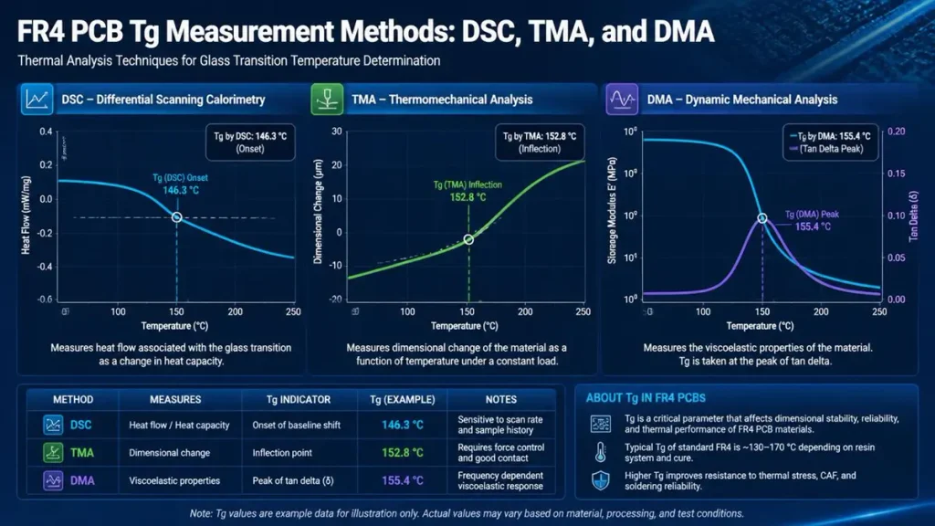
Comparison of FR4 PCB Tg Measurement Methods: How DSC, TMA, and DMA Affect Reported Values
The reported Tg can vary with the measurement method, so an FR4 PCB specification should identify whether Tg was measured by DSC, TMA, or DMA.
IPC’s TM‑650 test‑method family includes separate methods for Tg and related thermal measurements, including TMA, DMA and DSC methods.
| Test Method | Primary Measurement Principle | Engineering Use |
|---|---|---|
| DSC | Detects thermal transition associated with heat‑flow change | Common laminate Tg specification |
| TMA | Measures dimensional change with temperature | Tg and Z‑axis expansion evaluation |
| DMA | Measures mechanical response/modulus versus temperature | Tg and mechanical transition characterization |
These methods do not necessarily produce identical numerical Tg values.
Panasonic’s R‑1755E, for example, publishes Tg values of 133°C by DSC, 133°C by TMA, and 153°C by DMA, demonstrating why a buyer should not compare Tg numbers without checking the measurement method.
This is a critical procurement detail.
If Supplier A quotes:
Tg = 180°C
and Supplier B quotes:
Tg = 175°C
the difference may appear significant.
But if the two values were obtained using different methods, the comparison may not be technically equivalent.
What Should a PCB Buyer Put on the Material Specification?
A better requirement is:
Laminate: [exact manufacturer + grade] Tg: ≥XXX°C Tg method: [DSC/TMA/DMA] Td: ≥XXX°C Z‑axis CTE: supplier datasheet value T260/T288: supplier datasheet value Applicable IPC material specification: [required class/specification]
This eliminates much of the ambiguity encountered during RFQ comparison.
How Does Operating Temperature Determine FR4 Tg?
Operating temperature is the starting point for Tg selection, but the required Tg should be determined from the complete thermal environment rather than by applying one universal temperature margin.
The PCB’s actual temperature can be considerably different from the surrounding ambient temperature.
For example: Ambient = 45°C
does not necessarily mean: PCB operating temperature = 45°C
A power converter, motor controller, AI accelerator board, LED driver, or automotive control module can generate substantial internal heat.
A practical thermal assessment should therefore distinguish between:
- ambient temperature,
- enclosure temperature,
- PCB local temperature,
- component case temperature,
- copper temperature,
- hotspot temperature,
- transient temperature,
- long‑duration operating temperature.
Why Does the Actual PCB Temperature Matter?
Imagine two products:
Product A
- Ambient: 25–45°C
- PCB hotspot: 65°C
- Limited thermal cycling
- Four‑layer construction
Product B
- Ambient: 40–85°C
- PCB hotspot: 120°C
- Frequent power cycling
- 16‑layer construction
- High copper content
- Multiple BGA packages
Both may use FR4, but the material‑selection risk is very different.
For Product A, a conventional FR4 candidate may be technically adequate.
For Product B, a higher‑Tg, lower‑expansion, high‑reliability laminate may deserve evaluation.
The correct selection is therefore based on the temperature history, not the nominal product category.
How Does Thermal Cycling Affect FR4 Tg Selection?
Thermal cycling increases the importance of the laminate’s Tg, Z‑axis CTE, modulus, interconnect construction, and resistance to repeated thermal stress.
Every thermal cycle causes dimensional movement.
For a multilayer PCB, the resin system, glass reinforcement, copper, plated vias, solder joints, components, and mechanical interfaces do not expand at exactly the same rate.
This creates mechanical strain.
A simplified reliability chain is: Temperature change → material expansion → interconnect strain → repeated cycling → fatigue accumulation
The higher the number of cycles, the more important this accumulated strain becomes.
What Happens Around and Above Tg?
As the resin approaches its glass transition region, its mechanical behavior changes.
The Z‑axis expansion behavior can increase substantially above Tg.
That matters because plated through‑holes and microvias constrain or interact with this expansion.
For a multilayer PCB, excessive Z‑axis expansion can contribute to stress on:
- plated barrels,
- interlayer connections,
- microvia structures,
- resin interfaces,
- solder joints.
This is why thermal reliability should never be reduced to a single Tg number.
A laminate with a slightly lower Tg may outperform another laminate in a specific application if it provides a more suitable combination of CTE, decomposition resistance, thermal cycling performance and mechanical properties.
Does FR4 Tg Need to Be Higher Than Reflow Temperature?
No. FR4 Tg does not need to exceed the peak reflow temperature.
This is one of the most common misunderstandings in PCB material selection.
Lead‑free reflow temperatures can reach approximately 235–260°C, depending on solder alloy, process window and assembly profile.
A conventional or high‑Tg laminate may have a Tg substantially below that peak.
That does not automatically mean the laminate is unsuitable.
Why? Because Tg is not the maximum allowable processing temperature.
Reflow is a controlled, relatively short‑duration thermal exposure. The material must be evaluated against the complete thermal profile and its relevant reliability characteristics.
The more appropriate questions are:
- What is the peak temperature?
- How long does the board remain above key temperatures?
- How many reflow cycles occur?
- What is the laminate’s Td?
- What are its T260/T288 characteristics?
- What is the Z‑axis CTE?
- Is the board moisture‑conditioned?
- What PCB construction is being used?
For demanding assemblies, these parameters provide a much more meaningful reliability picture than simply comparing Tg with the reflow peak.
How Does FR4 Tg Affect Z‑Axis Expansion and Thermal Reliability?
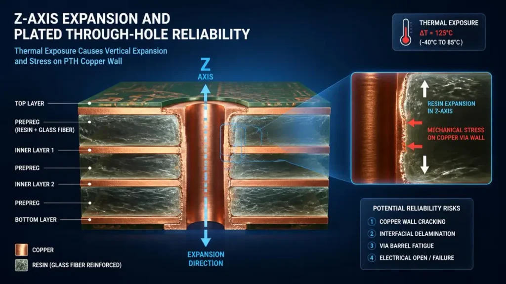
3D Technical Illustration: Z-Axis Thermal Expansion and Plated Through-Hole (PTH) Mechanical Stress
Tg influences the temperature region in which resin behavior changes, while Z‑axis CTE describes how strongly the material expands through the board thickness. Both should be considered when evaluating multilayer thermal reliability.
The Z‑axis direction is particularly important because PCB interconnections pass through the board thickness.
A high‑layer‑count board may contain hundreds or thousands of plated interconnections.
Repeated expansion and contraction can impose stress on these structures.
A laminate datasheet may therefore report:
- Z‑axis CTE below Tg,
- Z‑axis CTE above Tg,
- total Z‑axis expansion,
- T260,
- T288,
- Td.
For example, Isola’s 370HR material documentation reports a Tg around 180°C, Td around 340°C, and Z‑axis CTE values that increase significantly above Tg, illustrating why the thermal profile cannot be evaluated from Tg alone.
The practical engineering lesson is simple:
Tg tells you where a major resin transition occurs; Z‑axis CTE helps quantify dimensional movement associated with that thermal environment.
For multilayer reliability, both matter.
How Does FR4 Tg Affect Delamination?
A suitable Tg can improve thermal margin, but delamination resistance depends on the complete laminate system, thermal exposure, moisture condition, construction and process quality.
Delamination is influenced by multiple factors, including:
- thermal decomposition,
- resin cure,
- resin content,
- glass style,
- moisture,
- lamination pressure,
- heating rate,
- cooling rate,
- copper distribution,
- repeated reflow,
- thermal cycling.
That is why T260 and T288 can be useful alongside Tg.
A laminate with a high Tg but poor resistance to prolonged thermal exposure should not automatically be treated as a better choice than a well‑qualified lower‑Tg material.
Why Are T260 and T288 Useful?
T260 and T288 describe time‑to‑delamination behavior under specified thermal conditions.
They answer a different question from Tg.
Tg asks:
At what temperature does the resin system undergo its glass transition?
T288 asks:
How long can the material resist delamination under a defined 288°C thermal exposure?
These are related but different properties.
For demanding PCB applications, both may belong in the qualification matrix.
What FR4 Tg Should You Choose for Your PCB?
Choose the lowest material‑performance level that satisfies the complete operating, assembly and reliability requirements with appropriate engineering margin—not simply the highest available Tg.
A practical selection matrix is:
| PCB Requirement | Initial Material Direction |
|---|---|
| Moderate temperature, limited thermal cycling | Standard Tg FR4 may be suitable |
| Moderate temperature with repeated reflow | Compare standard and mid/high‑Tg materials |
| Elevated operating temperature | High‑Tg candidate should be evaluated |
| High‑layer‑count PCB | High‑reliability laminate evaluation recommended |
| Automotive electronics | Evaluate Tg + CTE + Td + thermal cycling |
| Industrial power electronics | Evaluate thermal profile and copper/interconnect stress |
| HDI/microvia construction | Evaluate Tg, Z‑CTE, T260/T288 and via reliability |
| High‑reliability product | Qualify exact laminate grade and process |
| Extreme thermal environment | Consider high‑Tg or specialized laminate systems |
This table is a screening tool, not a substitute for material qualification.
A Practical Selection Sequence
A procurement or engineering team can use this sequence:
Step 1 — Determine the actual temperature Measure or estimate the PCB hotspot rather than relying only on ambient temperature.
Step 2 — Define thermal cycling Estimate:
- cycles per day,
- cycles per year,
- qualification cycles,
- minimum temperature,
- maximum temperature,
- heating/cooling rate.
Step 3 — Define assembly exposure Document:
- solder alloy,
- peak reflow temperature,
- time above liquidus,
- number of reflow cycles,
- selective soldering,
- wave soldering,
- rework exposure.
Step 4 — Establish laminate requirements Specify:
- Tg,
- Tg test method,
- Td,
- Z‑axis CTE,
- T260/T288,
- modulus where relevant,
- moisture requirements.
Step 5 — Check PCB construction Review:
- layer count,
- board thickness,
- copper weight,
- via type,
- microvia structure,
- aspect ratio,
- BGA density,
- resin distribution.
Step 6 — Qualify the complete design The final decision should be based on the actual PCB stackup and reliability requirements rather than the Tg number alone.
What Should Buyers Specify in an FR4 PCB RFQ?
A professional FR4 PCB RFQ should specify the exact laminate grade or minimum material requirements, Tg test method, thermal properties, assembly exposure and reliability requirements.
A useful procurement checklist is:
| RFQ Item | Recommended Requirement |
|---|---|
| Base material | FR4 or exact approved laminate family |
| Tg | Minimum required value |
| Tg method | DSC, TMA or DMA |
| Td | Minimum requirement where applicable |
| Z‑axis CTE | Datasheet value or maximum |
| T260 | Minimum requirement if applicable |
| T288 | Minimum requirement if applicable |
| Layer count | Exact design requirement |
| Board thickness | Nominal + tolerance |
| Copper weight | Inner/outer copper specification |
| Thermal cycling | Temperature range + cycle count |
| Reflow | Peak temperature + number of cycles |
| Material approval | Manufacturer + exact grade |
| Certification | Required IPC/UL/customer requirements |
| Traceability | Lot/batch documentation where required |
Why Should the Exact Laminate Grade Be Named?
Suppose three suppliers quote:
- “FR4 high Tg”
- “FR4 Tg 170°C”
- “FR4 Tg 180°C”
These quotes are still difficult to compare.
A stronger RFQ might state:
Approved laminate: Manufacturer / Grade Tg: ≥180°C by DSC Td: ≥340°C Z‑axis CTE: ≤specified value T288: ≥specified time Construction: according to approved stackup
This turns a marketing label into a measurable procurement requirement.
What Manufacturing Factors Can Influence FR4 Thermal Reliability?
PCB fabrication does not raise the intrinsic Tg of a laminate, but lamination, drilling, plating, curing, moisture control and process stability determine whether the finished PCB preserves the intended material and interconnect reliability.
This distinction is important.
A PCB factory cannot make a 140°C laminate become a 180°C laminate simply through manufacturing.
What a qualified manufacturer can control is whether the material is processed correctly.
Key manufacturing controls include:
Lamination Control
Lamination must achieve the required:
- temperature profile,
- pressure profile,
- vacuum condition,
- resin flow,
- cure,
- layer registration.
Poor lamination can create voids, resin‑rich or resin‑starved regions, poor bonding, or dimensional problems even when the laminate itself has excellent thermal properties.
Drilling and Via Reliability
Thermal expansion interacts directly with plated structures.
For high‑layer‑count and HDI boards, drilling quality, desmear, copper deposition and via fill become increasingly important.
A material with suitable Tg cannot compensate for a defective plated barrel or poorly formed microvia.
Copper Distribution
Large differences in copper density can create localized thermal and mechanical behavior during lamination and assembly.
Copper balancing, plane design and stackup symmetry therefore remain relevant to dimensional stability.
Moisture Management
Moisture can influence thermal behavior during assembly.
For demanding applications, material storage, baking requirements, handling and pre‑assembly conditioning should be defined as part of the manufacturing process.
How Does Hongda Circuit Support FR4 Tg Material Selection?
Shenzhen Hongda Circuit Technology Co., Ltd. supports FR4 and high‑Tg material selection as part of stackup engineering, multilayer fabrication, HDI processing, lamination control and inspection rather than treating Tg as an isolated purchasing parameter.
Hongda’s published 2026 capability information lists FR‑4 and multiple high‑performance laminate families and supports multilayer PCB production for applications including industrial electronics, automotive electronics, high‑performance computing and other demanding applications.
The manufacturing workflow can include: Material selection → Stackup review → Lamination → Laser/mechanical drilling → Desmear → Plating → Imaging → Etching → AOI/inspection → Electrical test → Final quality review
For high‑density applications, Hongda also publishes capabilities involving laser‑drilled microvias, high‑Tg FR4, controlled impedance and advanced multilayer structures.
The important engineering point is that manufacturing technology and material selection must work together.
For example, a high‑Tg multilayer PCB may require tighter control of:
- resin flow,
- layer registration,
- copper balance,
- lamination,
- drilling,
- plating,
- microvia formation,
- dimensional inspection.
The factory’s role is not to “increase” the laminate’s Tg. Its role is to preserve the material’s designed performance while producing the required PCB geometry and interconnect structure.
What Are the Most Common FR4 Tg Selection Mistakes?
The most common mistakes are treating Tg as maximum operating temperature, comparing Tg values without checking the test method, assuming high Tg automatically means higher reliability, and specifying “high Tg FR4” without defining measurable requirements.
Mistake 1: Treating Tg as Maximum Operating Temperature
Tg is a transition characteristic, not a simple maximum‑use‑temperature rating.
The correct operating‑temperature limit must come from the specific material and application qualification.
Mistake 2: Comparing Tg Without Checking the Test Method
A DSC value and a DMA value should not automatically be treated as equivalent.
Always identify the method.
Mistake 3: Choosing the Highest Tg Available
Higher Tg can be useful, but the material must be evaluated as a system.
A high Tg does not automatically guarantee:
- lower CTE,
- higher Td,
- longer T288,
- better via reliability,
- better thermal cycling.
Mistake 4: Ignoring Thermal Cycling
A PCB can operate below its Tg for most of its life and still experience severe reliability stress if it undergoes thousands of temperature cycles.
Mistake 5: Specifying Only “High Tg FR4”
This wording is too broad for controlled procurement.
Specify the:
- manufacturer,
- material grade,
- Tg,
- test method,
- Td,
- CTE,
- T260/T288,
- approved equivalent rules.
What Is the Best FR4 Tg for Automotive and Industrial PCBs?
There is no single Tg value that is optimal for every automotive or industrial PCB; the correct value depends on temperature exposure, cycling requirements, PCB construction and qualification criteria.
Automotive electronics often combine:
- elevated ambient temperatures,
- local component heating,
- vibration,
- repeated thermal cycling,
- long service life,
- high reliability requirements.
Industrial electronics may combine:
- high copper weight,
- power conversion,
- large thermal gradients,
- continuous operation,
- enclosure heat,
- frequent power cycling.
In both cases, a higher‑Tg FR4 may be a strong candidate, but the final material should be selected using the full thermal‑reliability data.
For example, Panasonic’s R‑1755E publishes a DSC/TMA Tg of 133°C but a DMA Tg of 153°C, Td of 370°C, and T288 performance data, illustrating again that a single “Tg” number does not fully describe laminate thermal performance.
How Should Engineers Document FR4 Tg in the PCB Stackup?
The stackup should identify the laminate family or approved material, while the fabrication specification should define the minimum thermal properties and approved substitutions.
A robust stackup documentation package can include:
Core / Prepreg
- Manufacturer
- Material grade
- Thickness
- Resin content
- Tg
- Dk/Df where relevant
Thermal properties
- Tg method
- Td
- Z‑axis CTE
- T260/T288
Fabrication requirements
- Lamination cycle
- Copper weight
- Finished thickness
- Layer registration
- Via structure
Qualification requirements
- Thermal cycling
- Reflow exposure
- Electrical testing
- Cross‑section requirements
This level of documentation reduces the risk of an apparently equivalent laminate being substituted without engineering review.
FR4 PCB Glass Transition Temperature FAQ
What Is the Typical Tg of FR4 PCB Material?
Conventional FR4 materials are often around 130–150°C Tg, while high‑Tg FR4 materials are commonly around 170°C or higher. However, these are market‑level ranges rather than universal specifications. The exact Tg must come from the laminate datasheet and test method.
Is High Tg FR4 Better Than Standard Tg FR4?
Not automatically. High Tg FR4 can provide additional thermal margin for demanding applications, but reliability also depends on Z‑axis CTE, Td, T260/T288, thermal cycling, construction and manufacturing quality.
What Tg Should I Choose for an FR4 PCB?
Start with the actual PCB operating temperature and thermal‑cycle profile, then evaluate reflow exposure, board construction and reliability requirements. Standard Tg may be adequate for moderate applications; high‑Tg material is often worth evaluating for elevated‑temperature or high‑cycle applications.
Does FR4 Tg Have to Be Higher Than Reflow Temperature?
No. Tg does not represent the maximum reflow temperature. A suitable laminate must be qualified against the actual soldering profile, number of thermal exposures, Td, delamination behavior and other thermal‑reliability characteristics.
Should Tg Be the Only Thermal Property in an FR4 RFQ?
A robust RFQ should normally consider Tg together with Tg test method, Td, Z‑axis CTE, T260/T288 and the PCB’s thermal‑cycling and assembly requirements.
Final Engineering Takeaway
The right FR4 PCB glass transition temperature is not simply the highest number available.
The correct selection follows a more reliable engineering sequence: Actual PCB temperature → Thermal cycling → Assembly profile → PCB construction → Tg requirement → Td/CTE/T260/T288 → Material qualification → Manufacturing control
For a low‑stress application, standard Tg FR4 may be the most economical and technically appropriate solution.
For elevated‑temperature, high‑layer‑count, repeated‑reflow or high‑reliability applications, high‑Tg FR4 may provide a more suitable starting point.
The final decision should always be based on the exact laminate grade and its complete thermal‑performance data, not on the phrase “standard Tg” or “high Tg” alone.
Need Help Selecting the Right FR4 Tg?
If your PCB has a demanding thermal profile, high layer count, HDI construction, heavy copper, repeated reflow, automotive requirements or long‑life industrial operation, provide the stackup, operating temperature and assembly profile for an engineering material review.
Request a High‑Tg FR4 PCB Review from Shenzhen Hongda Circuit Technology Co., Ltd. Email:pcb@pcbkr.com
About Author
David Chen https://www.linkedin.com/in/pcbcoming
David Chen boasts an extensive professional background in PCBA manufacturing, PCBA testing, and PCBA optimization, with specialized expertise in high-precision PCBA fault analysis and rigorous PCBA reliability testing. The author has worked with high-layer-count server PCB fabrication, ultra-low-loss backplane stackups, and thermo-mechanical reliability optimization for AI infrastructure projects involving 112G and 224G PAM4 architectures. Skilled in complex circuit design and cutting-edge advanced PCB manufacturing processes, he delivers solutions that elevate product durability and performance across industrial applications. His technical articles focusing on PCBA manufacturing workflows and testing methodologies are widely cited by industry peers, research institutions, and technical platforms, solidifying his reputation as a recognized technical authority in the global circuit board manufacturing sector.