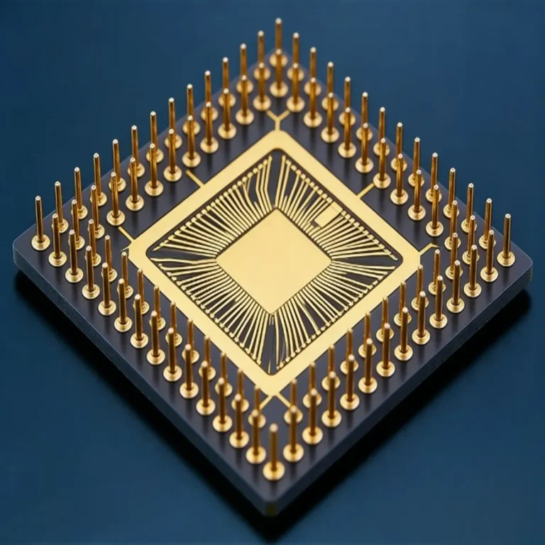
](https://www.pcbkr.com/wp-content/uploads/2026/10/server-bmc-remote-management-board-cover-1.webp)
How Do You Source a Reliable Server BMC Remote Management Board Manufacturer?
A reliable Server BMC Remote Management Board PCBA manufacturer must control more than PCB fabrication and SMT assembly. Buyers should verify board architecture, server-platform compatibility, component sourcing, fine-pitch assembly, inspection methods, revision control, and the agreed functional-testing scope before approving production.
For server OEMs and hardware developers, these controls help reduce connector incompatibility, BGA soldering defects, unstable power-management interfaces, and costly engineering changes between prototype and mass production.
Shenzhen Hongda Circuit Technology Co., Ltd. (PCBKR) provides PCB fabrication and PCBA manufacturing support for prototype, small-batch, and production requirements. Our manufacturing capabilities include precision imaging, laser drilling, multilayer lamination, SMT assembly, AOI, X-ray, and electrical inspection. The manufacturing process can be reviewed against the specific BMC board design and customer acceptance requirements.
1. What Should Buyers Specify When Sourcing a Server BMC Remote Management Board?
Buyers should first identify whether they need an embedded BMC circuit board, a separate BMC management module, or a DC-SCM-compatible board. These architectures can have different mechanical dimensions, connector arrangements, power interfaces, and manufacturing requirements.
A Baseboard Management Controller (BMC) provides out-of-band server management independently of the host operating system. Depending on the platform, its functions may include hardware monitoring, remote power control, event logging, and communication through management interfaces such as IPMI or Redfish.
However, the term BMC board does not always describe the same hardware.
| Board architecture | Typical configuration | Important manufacturing considerations |
|---|---|---|
| Embedded BMC | BMC controller integrated into the server motherboard | Mainboard layout, BGA assembly, power sequencing, and interface routing |
| Independent BMC management board | Separate PCB connected to a server motherboard | Board dimensions, connector pinout, mechanical alignment, and signal compatibility |
| DC-SCM-compatible module | Modular management board connected through a defined platform interface | Module specification, connector design, power interfaces, high-speed signals, and platform compatibility |
Why does this distinction matter during procurement?
Consider a server hardware developer moving from an embedded management design to a modular management architecture.
The new board may have a different connector layout, mechanical envelope, power input, and signal assignment. Even if the BMC controller and firmware platform remain similar, the PCB design and PCBA assembly requirements can change significantly.
A manufacturer should not assume compatibility from the BMC chip model alone.
Before requesting a quotation, buyers should provide:
- Target server motherboard or platform model.
- BMC board architecture and revision.
- PCB dimensions and mechanical drawings.
- Connector part numbers and pin assignments.
- Power input and power sequencing requirements.
- Required management interfaces.
- Expected prototype and production quantities.
These details establish the actual manufacturing scope and reduce the risk of quoting an incorrect board configuration.
2. Which Technical Specifications Affect BMC Board Manufacturing?
BMC board manufacturing is influenced by PCB layer count, component density, BGA pitch, connector geometry, power distribution, and interface routing. These parameters determine the fabrication process, material selection, assembly controls, and inspection requirements.
The following specifications should be reviewed during engineering quotation.
| Design parameter | Information required from the buyer | Manufacturing impact |
|---|---|---|
| PCB layer count | Exact number of copper layers | Lamination sequence, registration, drilling, and fabrication cost |
| Board thickness | Finished thickness and tolerance | Mechanical fit and connector alignment |
| Copper weight | Copper thickness by layer | Current capacity, etching compensation, and thermal performance |
| Minimum trace/space | Actual design requirement | Imaging and etching process selection |
| Microvia diameter | Finished or drilled diameter, as specified | Laser drilling, plating, and via reliability |
| BGA pitch | Component package and pitch | Solder-paste printing, placement accuracy, reflow, and X-ray inspection |
| Connector specification | Manufacturer part number, footprint, and pinout | Mechanical and electrical compatibility |
| Impedance | Required impedance values and tolerances | Stack-up design, dielectric selection, and impedance control |
| Power requirements | Input voltage, current, and transient conditions | Copper distribution, thermal design, and electrical inspection |
| PCB revision | Revision number and controlled design files | Production traceability and engineering change management |
Which specifications create the most manufacturing difficulty?
Fine-pitch BGA assembly, dense connector areas, and multilayer registration are common sources of manufacturing risk.
For example, a BMC board may contain a fine-pitch BGA controller, memory devices, power-management components, and multiple board-to-board connectors. These components create different process demands on the same assembly.
A small soldering defect under a BGA can interrupt a management interface without producing an obvious external visual defect. Similarly, a connector that is slightly misaligned may prevent correct mating with the server motherboard even when the electrical netlist is correct.
For multilayer boards, the challenge starts earlier. Layer-to-layer registration, dielectric thickness, copper distribution, and drilling position must be controlled together. A design with dense escape routing around a BGA may require HDI structures or microvias, but these should be selected according to the actual routing and reliability requirements.
PCBKR’s related manufacturing capabilities include HDI PCB manufacturing and microvia PCB manufacturing.
3. What Files Should Buyers Provide for a BMC PCBA Quotation?
A complete BMC PCBA quotation package should include PCB fabrication data, BOM, assembly files, mechanical information, interface specifications, and the required test scope. Gerber files and a BOM alone may not be sufficient to evaluate platform compatibility or functional-testing responsibility.
| Required file or information | Purpose | What the manufacturer should review |
|---|---|---|
| Gerber, ODB++, or IPC-2581 | PCB fabrication | Layer data, apertures, dimensions, and manufacturing notes |
| Stack-up drawing | PCB construction | Layer sequence, dielectric thickness, copper weight, and finished thickness |
| BOM | Component sourcing | Manufacturer part numbers, package, lifecycle, and approved alternatives |
| Pick-and-place file | SMT assembly | Coordinates, rotation, component side, and placement data |
| Assembly drawing | Assembly instructions | Polarity, orientation, reference designators, and special requirements |
| Mechanical drawing | Mechanical compatibility | Board outline, connector location, mounting holes, and clearance |
| Connector pinout | Interface verification | Signal assignment, power pins, ground pins, and mating requirements |
| PCB and BOM revision | Change control | Matching design revisions across fabrication and assembly |
| Test specification | Inspection and functional testing | Test points, equipment, procedure, limits, and pass/fail criteria |
What happens when the quotation package is incomplete?
A common procurement problem occurs when a buyer submits a BOM with generic component descriptions but without manufacturer part numbers.
For example, two components may have the same package dimensions but different electrical characteristics, temperature ratings, or communication behavior. Treating them as interchangeable can create problems during prototype validation or later production.
A similar problem occurs when the manufacturer receives an assembly drawing but no connector pinout or mechanical mating information. The PCBA may pass ordinary visual inspection and still fail to connect correctly to the target motherboard.
Engineering recommendation: Before releasing the first production lot, reconcile the Gerber or ODB++ revision, BOM revision, assembly drawing, and test specification. They should all refer to the same approved design release.
4. How Can Manufacturers Control BMC Board Compatibility and Assembly Risks?
Compatibility should be checked at the electrical, mechanical, and assembly levels—not inferred from the BMC controller model or connector appearance.
A BMC board can be correctly fabricated and assembled but still fail in its intended server platform if the connector pin assignment, GPIO behavior, power sequence, or mechanical arrangement is incorrect.
Electrical compatibility
The engineering review should cover:
- Connector pin assignment and signal direction.
- Power input voltage and current requirements.
- Ground and return-path allocation.
- GPIO logic levels and control behavior.
- Reset and power-control signals.
- I²C or I³C, SPI, UART, USB, PCIe, and NCSI interfaces where used.
- Pull-up and termination requirements where specified.
- Interface protection and electrical limits.
The actual interfaces depend on the server architecture. A manufacturer should work from the approved schematic, netlist, and interface documentation rather than assume that every BMC board uses the same signals.
Mechanical compatibility
Mechanical problems often appear during prototype integration rather than during PCB electrical inspection.
Typical risks include:
- Connector position offset from the approved drawing.
- Board outline or thickness outside the mating assembly’s tolerance.
- Mounting-hole misalignment.
- Component height interference.
- Insufficient clearance around board-to-board connectors.
- Incorrect connector orientation or assembly rotation.
For a removable BMC or DC-SCM module, connector alignment and insertion conditions are particularly important. A small mechanical deviation can create intermittent contact or prevent proper installation.
Assembly-related risks
Fine-pitch BGA and connector assembly require controls beyond ordinary visual inspection.
| Manufacturing risk | Possible consequence | Appropriate control |
|---|---|---|
| BGA solder voids or opens | Intermittent or failed electrical connections | Reflow-process control and X-ray inspection |
| Component misalignment | Incorrect connections or mechanical interference | Placement verification and 3D AOI |
| Solder bridging | Short circuits between adjacent pins | Printing control, AOI, and electrical testing |
| Incorrect polarity | Circuit malfunction or component damage | BOM review, placement checks, and AOI |
| Connector solder defects | Intermittent management interface | Solder-joint inspection and suitable electrical checks |
| PCB warpage | BGA or connector assembly defects | Stack-up review, material selection, and assembly-process control |
Expert engineering consideration: When a board combines a BGA controller and several board-to-board connectors, do not review the BGA and connectors as isolated assembly items. The board’s warpage, component height, connector alignment, and solder-joint reliability interact. A successful prototype should therefore be evaluated in the actual mating configuration whenever the customer can provide the corresponding hardware.
5. Which PCB Fabrication Technologies Matter for BMC Remote Management Boards?
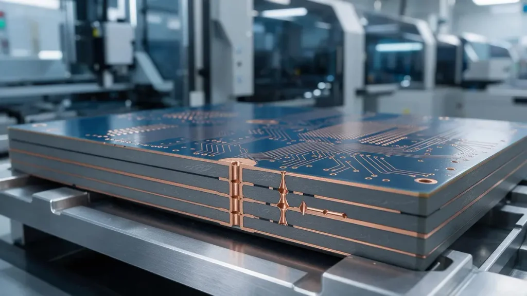
Advanced HDI PCB fabrication with fine-line copper traces and laser-drilled microvias for Server BMC Remote Management Boards.
The appropriate PCB technology depends on the board’s routing density, layer structure, component pitch, electrical requirements, and mechanical constraints. HDI, laser-drilled microvias, fine-line imaging, and controlled lamination can improve manufacturability when the design requires them; they should not be added simply to make a specification appear more advanced.
PCBKR’s equipment and process capabilities are relevant to several demanding PCB manufacturing requirements.
Precision imaging and fine-line pattern transfer
PCBKR uses SCREEN Ledia LDI equipment, with an 8 µm target imaging resolution and a stated process accuracy of ±10 µm.
For a dense BMC board, accurate pattern transfer is important around:
- Fine-pitch BGA escape routing.
- Dense connector fan-out.
- Narrow spacing between signal and power traces.
- Multilayer registration references.
- HDI structures where fine-line routing is required.
The practical benefit is better control of the imaging stage. However, final trace width and spacing depend on the complete imaging, etching, copper-plating, and inspection process—not the LDI specification alone.
For advanced designs requiring finer routing, PCBKR also has an mSAP process capability of 8/8 µm, established since Q3 2024. This is relevant when the approved design requires fine-line structures that conventional subtractive processing cannot reliably accommodate under the specified process window.
The actual finished geometry must be confirmed against the customer’s stack-up, copper thickness, design rules, and acceptance criteria.
Laser drilling and microvia formation
PCBKR’s stated laser capabilities include:
| Equipment or process | Stated capability | Potential application |
|---|---|---|
| Mitsubishi UV/CO₂ laser drilling | 75 µm ±5 µm | Microvia structures in dense multilayer designs |
| Picosecond laser drilling | 50 µm | Smaller laser-drilled features where the design and process permit |
For a compact BMC module, microvias may help route signals out of fine-pitch packages and reduce routing congestion. They can also support more compact layer transitions.
However, smaller via diameter is not automatically better. Via aspect ratio, copper plating, dielectric thickness, via position, and reliability requirements must be considered together.
A design using stacked or sequentially laminated microvias should be reviewed for its actual structure and reliability qualification requirements. Buyers should not assume that a stated laser diameter alone proves finished microvia reliability.
Multilayer lamination and registration
PCBKR uses LAUFFER lamination equipment with stated pressure settings of 80, 150, and 200 psi, and a vacuum level below 50 mbar.
These process controls are relevant to multilayer PCB construction, particularly where the board contains:
- Multiple dielectric and copper layers.
- Dense BGA escape routing.
- Buried or blind vias.
- Different copper distributions between layers.
- Controlled board thickness and registration requirements.
For example, an asymmetric copper layout can create uneven resin flow and contribute to board warpage. If the finished board must mate with a fixed server connector, dimensional stability becomes a functional requirement rather than merely an appearance issue.
The correct lamination recipe depends on the selected material system, stack-up, copper distribution, and manufacturing specification. The machine’s available pressure settings should not be mistaken for a universal recipe for every BMC board.
When should buyers request advanced PCB technology?
| Design condition | Possible manufacturing approach |
|---|---|
| High component density around the BMC controller | HDI or fine-line routing review |
| Fine-pitch BGA with limited escape-routing space | Microvia and via-in-pad design review |
| Dense multilayer interconnections | Controlled lamination and layer registration |
| High-speed interfaces with specified impedance | Controlled stack-up and impedance verification |
| Compact module with strict mechanical limits | Dimensional and warpage control |
The goal is to select the least complex process that reliably meets the electrical, mechanical, and production requirements. Over-specifying HDI or microvia structures can increase cost and qualification effort without improving the actual board function.
6. What Inspection and Testing Should Be Required for BMC PCBA Manufacturing?
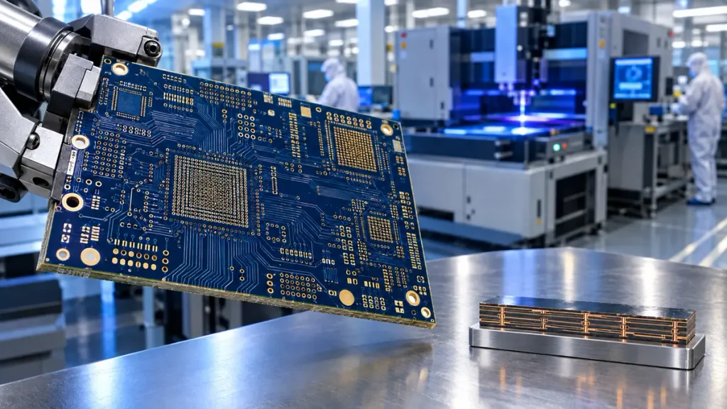
BGA X-ray inspection and PCBA quality control for Server BMC Remote Management Board manufacturing.
A BMC PCBA inspection plan should distinguish PCB electrical inspection, assembly inspection, and customer-defined functional validation. AOI and X-ray can identify manufacturing defects, but they cannot independently prove that the BMC operates correctly in the target server.
PCB fabrication inspection
Depending on the drawing and acceptance specification, PCB inspection may include:
- Finished board dimensions and thickness.
- Layer registration.
- Copper and dielectric structure.
- Drill position and hole quality.
- Electrical open and short testing.
- Impedance testing when controlled impedance is specified.
- Microsection analysis where required by the qualification plan.
PCBKR provides four-wire Kelvin flying-probe testing. This method is useful for measuring low-resistance electrical paths with reduced influence from lead and contact resistance.
For a BMC board, this can be relevant when verifying specified low-resistance connections or power-path characteristics. The test limits and test points must come from the approved design or customer test specification.
PCBA assembly inspection
| Inspection method | What it can detect or verify | Important limitation |
|---|---|---|
| 3D AOI | Component presence, position, polarity, and visible solder-joint conditions | Cannot inspect every hidden BGA solder joint |
| X-ray | Hidden solder-joint conditions under BGA and other suitable packages | Does not prove firmware or system functionality |
| Electrical testing | Open and short conditions and specified electrical paths | Coverage depends on accessible test points and test design |
| ICT | Component and circuit-level checks using a suitable fixture | Requires test access and a defined test program |
| Functional testing | Customer-defined board operation under specified conditions | Requires a valid test environment, firmware, and pass/fail criteria |
PCBKR’s 3D AOI and X-ray inspection capabilities can support the inspection of assembled BMC boards. The exact inspection coverage should be agreed according to package type, assembly complexity, and customer quality requirements.
What should a BMC functional test include?
A functional test should be based on the actual BMC platform and customer requirements. A possible test plan may include:
| Functional item | Example verification |
|---|---|
| Power input | Confirm specified input voltage and current behavior |
| Power sequencing | Verify the documented startup and shutdown sequence |
| BMC boot | Confirm successful startup using the approved firmware and platform |
| Management network | Verify network connectivity using the customer’s test configuration |
| Serial interface | Check UART or serial communication where applicable |
| Sensor monitoring | Verify expected sensor readings and status reporting |
| Remote power control | Test customer-defined power-on, power-off, and reset commands |
| Event logging | Confirm expected event reporting |
| Firmware recovery | Execute the agreed recovery procedure if included in the test scope |
| IPMI or Redfish | Verify the specified commands and responses using the customer’s environment |
PCBKR also has VNA measurement capability up to 70 GHz. This is relevant to designs that require high-frequency characterization or signal-integrity measurement. It should not be interpreted as a requirement for every BMC board or as automatic certification of all server interfaces.
Important responsibility boundary: BMC firmware development, platform integration, and system-level validation are not automatically included in ordinary PCB fabrication or PCBA assembly. Buyers should explicitly define whether PCBKR is responsible for firmware loading, fixture-based testing, or only the agreed manufacturing inspections.
To conduct meaningful functional testing, the customer may need to provide:
- Approved firmware image and version.
- Target server motherboard or test platform.
- Programming method and interface.
- Test fixture and required cables.
- Power-up sequence.
- Test software or commands.
- Expected outputs and pass/fail limits.
- Approved recovery procedure, if required.
Without these inputs, a manufacturer cannot responsibly claim that a board has passed complete server-level BMC validation.
7. How Should Buyers Control BMC Board BOM Changes and Production Revisions?
BMC board production requires controlled BOM revisions, approved component substitutions, and traceability between PCB and assembly releases. These controls are particularly important when the board contains controller ICs, memory, power-management devices, and platform-specific connectors.
Why are component substitutions risky?
Two components with similar package dimensions may differ in:
- Operating temperature range.
- Supply voltage and current characteristics.
- Timing or communication behavior.
- Power-on reset behavior.
- Memory capacity or compatibility.
- Manufacturer lifecycle status.
- Firmware or driver requirements.
A replacement component that fits the PCB footprint may still be electrically unsuitable for the approved design.
For example, replacing a power-management component without checking startup timing and output characteristics can affect the BMC’s power sequence. A connector substitution may introduce different pin assignments or mating geometry.
What should a component change-control process include?
| Control item | Required action |
|---|---|
| Approved BOM | Maintain manufacturer part numbers and approved sources |
| Alternative components | Obtain customer approval before substitution |
| Lifecycle monitoring | Identify EOL and availability risks |
| PCB revision | Record the approved fabrication revision |
| BOM revision | Match the assembly BOM to the released PCB revision |
| First article | Review the first assembled samples |
| Pilot production | Confirm process stability and customer acceptance |
| Production traceability | Record relevant material and production-lot information |
A practical production release should connect the PCB revision, BOM revision, assembly drawing, and test procedure. If any of these documents changes, the impact should be reviewed before manufacturing continues.
For OEM buyers planning long-term server production, this approach reduces the risk of receiving boards that are physically similar but built to different engineering revisions.
8. How Can Buyers Qualify a Server BMC Remote Management Board PCBA Manufacturer?
Buyers should evaluate a manufacturer on its engineering review, PCB process control, component sourcing, assembly inspection, traceability, and ability to follow the agreed test scope. A list of machines alone is not enough to establish that a supplier can deliver a reliable BMC board.
Use the following checklist when comparing suppliers.
| Supplier evaluation item | Questions buyers should ask |
|---|---|
| PCB engineering review | Can the supplier review stack-up, drill data, design rules, and fabrication notes? |
| HDI and microvia | Can the process be matched to the required via structure and reliability criteria? |
| Fine-pitch assembly | Can the supplier support the actual BGA pitch and package type? |
| Component sourcing | Are manufacturer part numbers and approved alternatives controlled? |
| AOI and X-ray | What packages and defects are covered by inspection? |
| Electrical testing | What test method, coverage, and acceptance limits are available? |
| Functional testing | Can the supplier follow customer-provided firmware and test procedures? |
| Revision control | Are PCB, BOM, assembly, and test revisions traceable? |
| Production transition | Is there a defined sample approval and production-release process? |
| Quality documentation | Can the supplier provide agreed inspection and production records? |
Why consider PCBKR for BMC board manufacturing?
Shenzhen Hongda Circuit Technology Co., Ltd. (PCBKR) supports PCB fabrication and PCBA assembly for electronic hardware developers and OEM buyers.
Relevant manufacturing resources include:
- SCREEN Ledia LDI: 8 µm target imaging resolution, with stated process accuracy of ±10 µm.
- mSAP: 8/8 µm fine-line process capability, established since Q3 2024.
- Mitsubishi UV/CO₂ laser: 75 µm ±5 µm stated drilling capability.
- Picosecond laser: 50 µm stated drilling capability.
- LAUFFER lamination: 80/150/200 psi pressure settings and vacuum below 50 mbar.
- 3D AOI and X-ray: Assembly inspection for visible and hidden solder-joint conditions.
- Four-wire Kelvin flying probe: Low-resistance electrical measurement.
- VNA: Measurement capability up to 70 GHz for designs requiring high-frequency characterization.
These resources are relevant when a BMC board requires fine-line routing, multilayer construction, microvia structures, fine-pitch assembly, or defined electrical inspection.
The final process selection and acceptance criteria must still be based on the customer’s released design, material requirements, and qualification plan. Not every BMC board needs mSAP, microvias, or high-frequency testing.
9. What Information Should You Include in a BMC Board PCBA RFQ?
A useful RFQ should allow the manufacturer to evaluate the PCB design, component sourcing, assembly complexity, inspection scope, and delivery requirements without guessing about the target platform.
For a more accurate quotation, prepare the following information:
| RFQ information | Details to provide |
|---|---|
| Product | Server BMC Remote Management Board or DC-SCM-compatible module |
| Target platform | Server motherboard model or platform specification |
| PCB data | Gerber, ODB++, or IPC-2581 |
| PCB construction | Layer count, stack-up, material, copper weight, and thickness |
| Assembly data | BOM, pick-and-place, and assembly drawing |
| Interface information | Connector part numbers, pinout, and signal requirements |
| Quantity | Prototype quantity, pilot quantity, and expected production volume |
| Component sourcing | Consigned, turnkey, or partial component sourcing |
| Testing | AOI, X-ray, electrical testing, ICT, or customer-defined FCT |
| Firmware | Whether programming is required and who supplies the firmware |
| Delivery | Required prototype and production lead time |
| Quality documents | Inspection reports and traceability requirements |
Request a BMC PCBA manufacturing quotation from PCBKR
PCBKR welcomes RFQs from overseas server OEMs, hardware design companies, and electronic product developers seeking PCB fabrication and PCBA manufacturing support.
Send your design package to sales@pcbkr.com.
For an initial engineering review, include the PCB files, BOM, assembly drawing, target platform information, and required inspection or testing scope. If the functional test depends on customer firmware or server hardware, specify the available test environment and responsibility split.
This allows the manufacturing team to assess process requirements, identify missing engineering information, and prepare a quotation based on the actual product configuration.
Frequently Asked Questions
How Do I Find a Reliable Server BMC Remote Management Board PCBA Manufacturer?
Look for a manufacturer with multilayer PCB fabrication, fine-pitch SMT assembly, BGA inspection, component sourcing, revision control, and documented electrical testing. Ask for evidence of the actual equipment and process capabilities relevant to your board, rather than relying only on general capability statements.
What Files Are Required for a BMC Remote Management Board PCBA Quote?
Prepare Gerber or ODB++ files, stack-up drawings, BOM with manufacturer part numbers, pick-and-place data, assembly drawings, board dimensions, and connector pinout information. Include the target server platform and testing requirements so the manufacturer can evaluate compatibility and production scope.
Can a PCBA Manufacturer Verify BMC Board Compatibility with a Server Motherboard?
A PCBA manufacturer can review the supplied PCB data, connector footprint, pin assignment, mechanical dimensions, and specified electrical requirements. Full platform compatibility requires the target motherboard, firmware, interface documentation, and an agreed integration test. PCB assembly inspection alone cannot prove complete server-level compatibility.
Does BMC PCBA Manufacturing Include Firmware Programming and Functional Testing?
Not automatically. PCB fabrication and PCBA assembly are separate from firmware development and system-level validation. Firmware loading and functional testing should be explicitly included in the quotation, with the customer providing the approved firmware, test procedure, fixtures, platform, and acceptance criteria where required.
What Tests Should Be Completed Before BMC Board Mass Production?
At minimum, buyers should define PCB electrical testing, assembly inspection, and first-article verification. Depending on the design, this may include 3D AOI, BGA X-ray, ICT, power-on checks, management-interface communication, sensor verification, and remote power-control tests. The final test plan should reflect the target platform and customer acceptance requirements.
David Chen LinkedIn Profile
David Chen is a Senior RF/PCB Process Engineer at Shenzhen Hongda Circuit Technology Co., Ltd., with over 12 years of experience in high-frequency PCB fabrication, impedance-controlled stack-up design, and Rogers/PTFE laminate processing. He also boasts an extensive professional background in PCBA manufacturing, PCBA testing, and PCBA optimization, with specialized expertise in high-precision PCBA fault analysis and rigorous PCBA reliability testing. The author has worked with high-layer-count server PCB fabrication, ultra-low-loss backplane stackups, and thermo-mechanical reliability optimization for AI infrastructure projects involving 112G and 224G PAM4 architectures. Skilled in complex circuit design and cutting-edge advanced PCB manufacturing processes, he delivers solutions that elevate product durability and performance across industrial applications. His technical articles focusing on PCBA manufacturing workflows and testing methodologies are widely cited by industry peers and technical platforms, and have gained attention and recognition from industry colleagues.