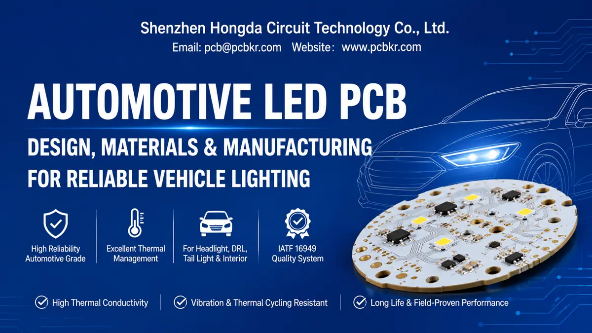
Automotive LED PCB Manufacturer for Car Lighting Systems
A tail light that flickers at 80 km/h on a rain-soaked highway. A headlight that shifts color temperature after six months of thermal cycling. An interior dome light that fails the first time the vehicle drives through a mountain pass at -30 °C. These are not component failures. They are automotive LED PCB failures—and they trace back to a single sourcing decision made months earlier.
The car LED PCB is the thermal, electrical, and mechanical foundation of every LED lighting module in a modern vehicle. Unlike consumer-grade LED boards, an automotive PCB for LED lighting must survive vibration spectra that would fracture standard solder joints, temperature swings from deep freeze to engine-bay heat, and salt-fog exposure that corrodes unprotected copper traces. At Shenzhen Hongda Circuit Technology Co., Ltd., we manufacture automotive LED PCBs for Tier 1 and Tier 2 suppliers who cannot afford field recalls. Our Shenzhen facility deploys LDI laser direct imaging, vacuum lamination with real-time pressure profiling, and AI-enhanced multi-station AOI to deliver car LED circuit boards that meet the thermal and reliability demands of headlight, DRL, tail light, and interior lighting programs.
If you are qualifying suppliers for an automotive lighting project, this page maps every material selection, design checkpoint, and quality verification step you need before releasing a production purchase order.
What Is an Automotive LED PCB? Definition and Application Scope
An automotive LED PCB is a printed circuit board engineered specifically to mount, interconnect, and thermally manage LED packages within vehicle lighting systems. The scope is precise: it serves automotive lighting modules only—not powertrain controllers, battery management systems, or infotainment boards.
The primary applications of a car LED PCB include:
- Headlight assemblies — high-beam, low-beam, and adaptive forward lighting modules
- Daytime running lights (DRL) — continuous-operation front signature lighting
- Tail lights and brake lights — rear visibility and stop indication
- Turn signals — directional indicators with rapid on/off cycling
- Interior lighting — dome lights, map lights, footwell illumination, and ambient lighting strips
The distinction matters because each application imposes a different thermal and mechanical load. A car headlight PCB operating at 40 W in a sealed housing faces a completely different stress profile than an automotive interior lighting PCB running 2 W in a climate-controlled cabin. Sourcing the wrong substrate for the wrong location is how automotive lighting programs fail validation.
Car LED PCB Major Applications — Matching Board Technology to Lighting Location
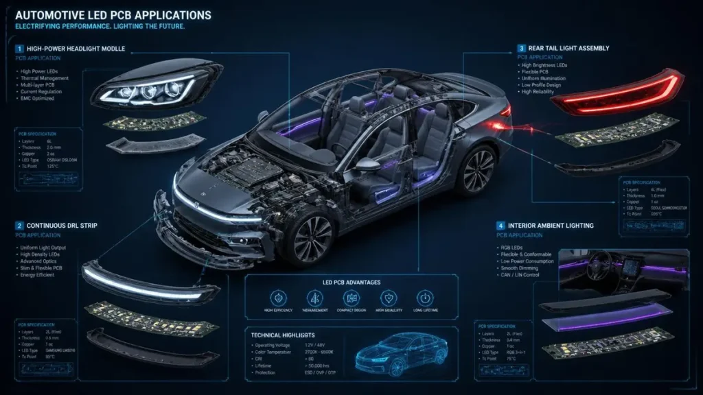
Automotive LED PCB Applications for Vehicle Lighting
Automotive lighting is not a single market. It is five distinct thermal and mechanical environments, each requiring a specific automotive LED PCB construction.
Headlight PCB for High-Power Forward Lighting
The car headlight PCB is the most thermally aggressive application in automotive lighting. Modern LED headlamp modules run 30–60 W per board in a housing with limited airflow and proximity to the engine compartment. Aluminum MCPCB with dielectric thermal conductivity of 2.0–3.0 W/mK is the baseline. For laser-assisted or matrix-beam systems exceeding 100 W, copper-core substrates with thermoelectric separation become necessary.
At Hongda Circuit, our headlight PCB production line handles aluminum base thicknesses up to 2.0 mm with 2–3 oz copper to manage both thermal spreading and current density. We validate every headlight board with thermal impedance testing to confirm dielectric performance matches the specification on your drawing.
DRL PCB for Continuous-Operation Daytime Running Lights
The car LED PCB for DRL daytime running light applications operates continuously whenever the vehicle is in motion. This means 100 % duty cycle for the life of the vehicle—often 10,000+ hours. Thermal management is less about peak power and more about steady-state heat rejection. Aluminum MCPCB at 1.5–2.0 W/mK is standard, with white solder mask to maximize reflector efficiency.
Tail Light PCB for Rear Visibility and Brake Indication
The automotive tail light PCB faces a dual-mode thermal profile: continuous low-power operation for tail illumination, punctuated by high-current pulses for brake light activation. The board must handle the thermal spike without delamination or solder joint fatigue. We typically specify high-Tg dielectric materials (Tg ≥ 170 °C) for tail light boards to prevent thermal cycling damage.
Turn Signal PCB for Directional Indicators
Turn signals cycle rapidly—typically 1–2 Hz flash rate—creating repetitive thermal shock. The car LED circuit board for turn signals must survive tens of thousands of on/off cycles without trace cracking or LED pad lifting. This requires robust copper-to-dielectric adhesion and controlled CTE (coefficient of thermal expansion) matching between layers.
Interior Lighting PCB for Cabin and Ambient Applications
The automotive interior lighting PCB operates at lower power but demands precise dimensional control for fitment into trim panels and overhead consoles. These boards often use thinner aluminum (0.8–1.0 mm) or high-Tg FR-4 for designs integrating driver ICs and control logic alongside the LED array.
Automotive LED PCB Material Selection — Substrate Architecture for Vehicle Environments
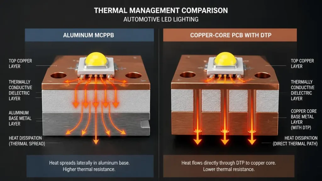
Aluminum MCPCB vs Copper-Core DTP PCB Thermal Management Comparison
Material selection for an automotive LED PCB is a thermal-mechanical decision, not a cost decision. The wrong substrate guarantees a field failure. The right substrate extends LED lumen maintenance life to match the vehicle warranty period.
Aluminum MCPCB for Standard Automotive LED Modules
Aluminum MCPCB (metal core printed circuit board) remains the default for most automotive PCB for LED lighting applications. The stack-up—copper circuit layer, thermally conductive dielectric, and aluminum base—provides a direct thermal path from the LED junction to the lamp housing.
At Hongda Circuit, our aluminum automotive LED PCB substrates use 5052 H32 alloy for formability and 6061 T6 for applications requiring CNC machining precision. Dielectric options range from 1.0 W/mK to 3.0 W/mK, selected based on LED power density and housing thermal resistance.
Copper-Core PCB for High-Power Headlight and Laser Applications
When LED power density exceeds what aluminum can reliably handle, a copper-core PCB becomes the only viable option. Copper delivers approximately 400 W/mK base thermal conductivity—double that of aluminum. The trade-off is weight and cost, but for matrix-beam headlights and laser-assisted forward lighting, there is no alternative.
We produce copper-core car headlight PCBs with direct thermal path (DTP) construction, where the LED thermal pad contacts the copper base directly, bypassing the dielectric layer entirely. This achieves thermal resistance figures that approach pure copper performance.
Ceramic PCB for Extreme Thermal Performance
For specialized automotive LED PCB applications where both electrical isolation and ultra-high thermal conductivity are required—such as UV curing lamps inside vehicle manufacturing lines or high-density micro-LED arrays—ceramic substrates (Al₂O₃ or AlN) provide 20–180+ W/mK thermal performance. We support ceramic automotive LED PCBs on a project-by-project basis with full material traceability.
Thermally Conductive Dielectric Layer — The Critical Interface
The dielectric layer is the most technically demanding component of any metal-core automotive LED PCB. It must provide electrical isolation (> 3 kV breakdown) while conducting heat efficiently. We specify ceramic-filled epoxy dielectric systems with proven automotive track records, matching thermal conductivity to the LED wattage density of each application.
Automotive LED PCB Thermal Design — Preventing Junction Temperature Creep
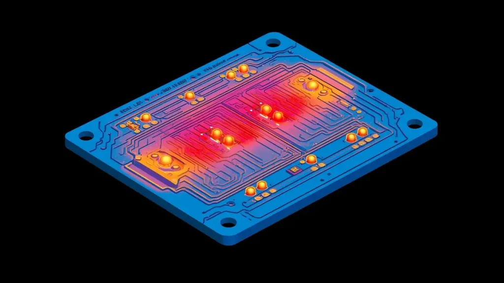
FEA Thermal Simulation Heatmap for Automotive Headlight LED PCB
Thermal failure in automotive lighting does not announce itself with smoke. It manifests as gradual lumen depreciation, color shift toward blue, and eventual solder joint fracture. The automotive LED PCB thermal design is the first line of defense.
The Thermal Path in a Car LED Circuit Board
Heat originates at the LED junction. It travels through the LED package slug, into the solder joint, across the copper trace, through the dielectric layer, and finally into the aluminum or copper base. The dielectric is the bottleneck. Even a 100 µm dielectric with 1.0 W/mK conductivity creates more thermal resistance than the entire 1.5 mm aluminum base beneath it.
Thermal Performance by Automotive Lighting Tier
| Application | LED Power Density | Recommended Automotive LED PCB |
|---|---|---|
| Interior dome/map lights | < 0.5 W per LED | Aluminum MCPCB, 1.0–1.5 W/mK |
| DRL, tail lights | 0.5–2 W per LED | Aluminum MCPCB, 1.5–2.0 W/mK |
| Headlights, fog lamps | 2–5 W per LED | Aluminum MCPCB, 2.0–3.0 W/mK |
| Matrix beam, laser assist | > 5 W per LED / COB | Copper-core PCB with DTP |
Copper Area and Trace Design for Heat Spreading
High-current LED traces must be wide and short. Narrow traces act as thermal resistors, creating localized hot spots. For automotive LED PCB designs running 1 A+ per string, we recommend 2 oz minimum copper thickness with trace widths calculated for both current capacity and thermal spreading. Our engineering team reviews every Gerber for thermal choke points during DFM—before your tooling budget is committed.
Automotive LED PCB Electrical Design Requirements — Adapting to Vehicle Power Systems
Automotive electrical systems are hostile environments. A car LED PCB must survive load dumps, reverse polarity events, and voltage transients that would destroy consumer-grade boards.
Vehicle Voltage Compatibility and Fluctuation
Automotive LED lighting operates nominally at 12 V or 24 V, but the actual bus voltage fluctuates between 9 V and 16 V in 12 V systems, with load-dump spikes exceeding 100 V. The automotive LED PCB must accommodate driver ICs and protection networks that handle these transients without failure.
LED Power and Driver Circuit Separation
On the automotive PCB for LED lighting, power traces carrying switching current to the LED strings must be physically separated from sensitive control and dimming signals. This separation prevents switching noise from coupling into analog dimming lines, which causes visible flicker.
Copper Thickness and Trace Width Selection
Current-carrying traces on a car LED circuit board must be sized for both steady-state current and inrush during cold-start. We validate trace widths against IPC-2152 standards, adjusting for the elevated temperatures typical in automotive engine-bay proximity. For high-current headlight modules, 3 oz copper is not uncommon.
Parasitic Inductance Minimization
Long, narrow current loops on an automotive LED PCB create parasitic inductance that generates EMI and voltage overshoot during PWM dimming. Our DFM review flags excessive loop area and recommends via stitching or ground plane return paths to minimize inductance.
Automotive LED PCB EMC and Layout Considerations — Controlling Emissions in a Noisy Vehicle
Automotive LED drivers are switch-mode power supplies. They generate electromagnetic noise. If the automotive LED PCB EMC layout is not controlled, that noise radiates through the wiring harness and interferes with radio reception, CAN bus communication, or ADAS sensors.
Minimizing High-Current Loop Area
The most effective EMC mitigation on a car LED PCB is geometric: minimize the area enclosed by the switching current path. Place the switching regulator, inductor, and input capacitor as close together as possible, with the current return directly beneath the forward path on an adjacent layer.
Input Filter Placement and Routing
The input filter block on an automotive lighting PCB must sit adjacent to the connector, not adjacent to the switching regulator. This prevents conducted noise from bypassing the filter through parasitic coupling. If physical separation is impossible, a local shield over the DC-DC block becomes necessary.
Ground Plane Integrity and Shielding
A solid ground plane on the automotive LED PCB acts as an EMI shield and provides a low-impedance return path. Avoid ground plane cutouts under high-speed switching nodes, as these force return currents to detour, creating radiating loops. For critical applications, we recommend four-layer construction with dedicated ground and power planes.
Heat Sink as EMC Shield
In many automotive headlight PCB designs, the metal heat sink doubles as an EMC shield. This only works if the heat sink has multiple, low-impedance connections to the PCB ground. A single grounding point can create a patch antenna effect, worsening emissions. We review heat sink grounding strategy during DFM.
Reliability Requirements in Automotive Environments — What Car LED PCBs Must Survive
A car LED PCB is not a consumer product. It is a safety-critical component subject to environmental stresses that most electronics never encounter.
Wide Temperature Range Operation
Automotive lighting must function from -40 °C to +125 °C, with some under-hood proximity applications requiring survival to +150 °C. At Hongda Circuit, we validate automotive LED PCB material systems for thermal cycling across this range, ensuring dielectric adhesion and solder joint integrity do not degrade.
Thermal Shock and Cycling Resistance
Every time a vehicle starts, the automotive LED PCB undergoes rapid thermal ramp. Headlights go from ambient to operating temperature in under 60 seconds. This repeated thermal shock causes CTE mismatch stress at material interfaces. We specify high-Tg dielectrics and robust copper peel strength to prevent delamination.
Vibration and Mechanical Stress
Vehicle vibration spectra—road-induced, engine-induced, and acoustic—create fatigue loading on solder joints and trace connections. An automotive tail light PCB mounted on a pickup truck bed sees a different vibration profile than an automotive interior lighting PCB in a luxury sedan. We design pad geometries and via structures to withstand the specific vibration environment of each application.
Humidity, Salt Fog, and Corrosion
Rear lighting modules are exposed to road spray containing de-icing salts. This creates an electrolytic corrosion risk for exposed copper edges. We specify ENIG surface finish for automotive LED PCBs in exposed locations, and we can apply conformal coating on request for additional environmental protection.
Long-Term Reliability and Material Traceability
Automotive OEMs require 10–15 year service life with full material traceability. At Hongda Circuit, every automotive LED PCB production lot is traceable to raw material certificates—aluminum alloy, dielectric batch, copper foil origin, and solder mask chemistry. This traceability is non-negotiable for Tier 1 suppliers.
Automotive LED PCB Manufacturing and Quality Control — The Hongda Circuit Production System
Manufacturing consistency is what separates prototype success from production reliability. Our automotive LED PCB manufacturing quality control system is built around process control, not just final inspection.
LDI Laser Direct Imaging for Trace Accuracy
We use LDI (Laser Direct Imaging) to pattern copper traces without photomask distortion. This achieves ±8 µm registration accuracy—critical for fine-pitch LED arrays and dense driver IC layouts on automotive LED PCBs. LDI eliminates the dimensional drift associated with film-based imaging, ensuring every panel matches the Gerber exactly.
Vacuum Hot Press Lamination for Void-Free Dielectric Bonding
Dielectric voids are the hidden killer of metal-core automotive LED PCBs. A void creates a localized thermal insulator, leading to LED hotspot failure. Our vacuum lamination presses operate with real-time pressure profiling and temperature ramp control, ensuring 100 % dielectric coverage without delamination risk.
AI-Enhanced Multi-Station AOI Inspection
Our production line integrates 2026-generation AOI systems with AI-driven defect classification, reducing false-call rates by up to 45 % compared to legacy 2D systems. For automotive LED PCB manufacturing, this means we catch trace width deviations, solder mask misregistration, and pad geometry errors before boards leave the factory floor—not after they arrive at your assembly house.
Electrical Testing and Thermal Validation
Every car LED circuit board undergoes 100 % flying probe or dedicated fixture electrical testing. For automotive programs, we add thermal impedance validation on sample boards from each production lot, confirming that dielectric thermal conductivity matches the specification on your drawing.
Material Certificate and Lot Traceability
We provide:
- Aluminum alloy certification (5052 / 6061)
- Dielectric material certificate with thermal conductivity data
- Copper foil tensile and elongation reports
- Solder mask chemistry and cure validation
- RoHS / REACH material declarations
This documentation package supports your PPAP submission and OEM traceability requirements.
Specifications to Confirm When Selecting Automotive LED PCB — The Buyer’s Checklist
Before requesting a quote, confirm these parameters. Ambiguity at this stage creates delays, respins, and cost overruns.
| Parameter | What to Specify | Why It Matters |
|---|---|---|
| LED lamp type | Headlight / DRL / tail / turn / interior | Determines thermal and mechanical requirements |
| PCB outline dimensions | Length, width, mounting hole pattern | Fitment into lamp housing |
| Board thickness | Typically 0.8–2.0 mm for aluminum | Mechanical compatibility with heat sink |
| Substrate type | Aluminum / copper / ceramic | Thermal budget and weight constraints |
| LED power and current | Watts per LED, string current | Drives copper thickness and dielectric selection |
| Copper thickness | 1 oz to 3 oz typical | Current capacity and heat spreading |
| LED package and pad size | 2835, 3528, 5050, COB, custom | Solder mask opening and pad geometry |
| Operating temperature range | -40 °C to +125 °C typical | Material system selection |
| Environmental protection | Conformal coating, ENIG, sealed edges | Salt fog and humidity resistance |
| Quantity and delivery | Prototype vs. production volumes | Tooling and scheduling |
Automotive LED PCB Quotation Guide — How to Request a Quote from Hongda Circuit
We respond to all automotive LED PCB RFQs within 24 hours. To receive an accurate, manufacturable quote, provide:
- Gerber files (RS-274X format)
- PCB mechanical drawing or DXF outline
- LED power specifications and electrical schematic
- Material and thermal requirements (substrate type, dielectric conductivity)
- Target application (headlight, DRL, tail, interior)
- Quantity and delivery timeline
Our engineering team performs DFM review on every automotive LED PCB inquiry, flagging thermal choke points, EMC loop areas, and manufacturability concerns before quoting.
Request an Automotive LED PCB Quote: pcb@pcbkr.com
Automotive LED PCB FAQ — Procurement Decision Support
What is the difference between an automotive LED PCB and a standard commercial LED PCB?
An automotive LED PCB is engineered for vehicle-specific environmental stresses: wide temperature range (-40 °C to +125 °C), continuous vibration, salt-fog exposure, and 10–15 year service life. The material system—dielectric, aluminum alloy, copper foil, and solder mask—is selected and validated for these conditions. A standard commercial LED PCB uses consumer-grade materials with no vibration or thermal cycling validation. Using a commercial board in an automotive application guarantees field failure.
What automotive headlight PCB thermal conductivity do I need for high-power LED modules?
For automotive headlight PCB applications running 2–5 W per LED, specify aluminum MCPCB with 2.0–3.0 W/mK dielectric thermal conductivity. For matrix-beam or laser-assisted systems exceeding 5 W per LED or 100 W total module power, copper-core PCB with direct thermal path (DTP) construction is required. Always request dielectric thermal resistance (Rth) data, not just a conductivity number, and confirm the value is measured, not theoretical.
How do I ensure my car LED PCB design passes automotive EMC requirements?
EMC compliance starts at the car LED PCB layout stage, not the test chamber. Minimize switching current loop area by placing the DC-DC regulator, inductor, and input capacitor in tight proximity. Route power and control traces separately. Maintain a solid ground plane without cutouts under switching nodes. If the LED load is remote (> 10 cm wiring), add common-mode filtering at the PCB connector. At Hongda Circuit, our DFM review flags EMC risk areas before production.
What surface finish is best for automotive LED PCB: ENIG, HASL, or OSP?
For exposed automotive LED PCBs in tail lights, turn signals, or under-hood locations, ENIG (Electroless Nickel Immersion Gold) is the standard. It provides oxidation resistance, flat solder joints, and shelf-life stability. HASL is acceptable for interior lighting with non-critical pad geometry. OSP works for single-reflow assemblies but lacks the long-term environmental protection required for exterior automotive lighting. We recommend ENIG for all exterior automotive LED PCB applications.
What quality documentation should I demand from an automotive LED PCB manufacturer?
Before placing a volume order, demand:
First Article Inspection (FAI) with dimensional report, copper thickness verification, and thermal impedance data
Material certificates proving aluminum alloy grade, dielectric thermal conductivity, and RoHS compliance
Process transparency including equipment list (LDI, AOI, flying probe), lamination parameters, and ISO 9001 certification
Lot traceability linking your production batch to raw material certificates
Hongda Circuit provides full FAI documentation with prototype orders and welcomes third-party inspection agency visits to our Shenzhen facility. A supplier unwilling to share material certificates or process details is a sourcing risk.
About Author
David Chen https://www.linkedin.com/in/pcbcoming
David Chen boasts an extensive professional background in PCBA manufacturing, PCBA testing, and PCBA optimization, with specialized expertise in high-precision PCBA fault analysis and rigorous PCBA reliability testing. The author has worked with high-layer-count server PCB fabrication, ultra-low-loss backplane stackups, and thermo-mechanical reliability optimization for AI infrastructure projects involving 112G and 224G PAM4 architectures. Skilled in complex circuit design and cutting-edge advanced PCB manufacturing processes, he delivers solutions that elevate product durability and performance across industrial applications. His technical articles focusing on PCBA manufacturing workflows and testing methodologies are widely cited by industry peers, research institutions, and technical platforms, solidifying his reputation as a recognized technical authority in the global circuit board manufacturing sector.