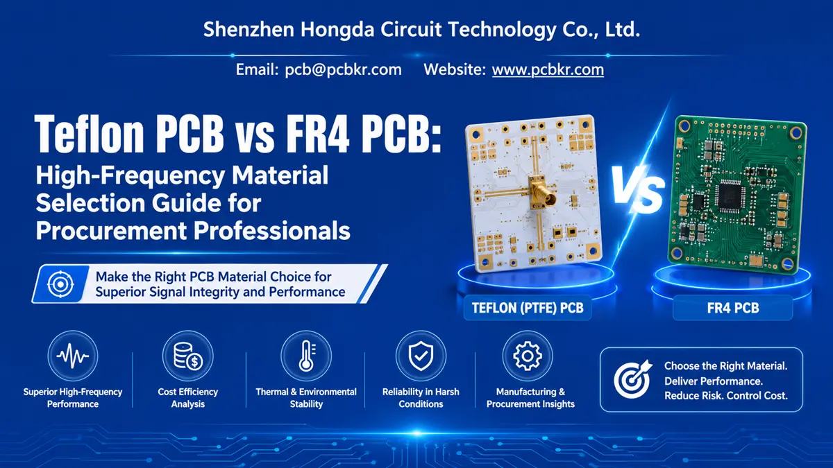
Teflon PCB vs FR4 PCB: High-Frequency Material Selection Guide for Procurement Professionals
When sourcing printed circuit boards for radio-frequency (RF), microwave, or millimeter-wave systems, the substrate you specify is not merely a cost line item—it is the foundation of signal integrity. Teflon PCB vs FR4 PCB represents one of the most consequential high-frequency PCB material comparisons procurement teams face today. The wrong choice can introduce insertion loss, impedance drift, and thermal degradation that no amount of post-fabrication tuning can fix. The right choice ensures stable performance from prototype through production.
This guide is written for purchasing managers, hardware engineers, and supply-chain professionals who need to move beyond datasheets and understand how PTFE PCB advantages translate into real procurement decisions. We will examine the material science, performance boundaries, cost structures, and manufacturing realities that determine whether a project belongs on Teflon (PTFE) or FR4.
What Is Teflon PCB? Understanding PTFE-Based Circuit Boards for RF Applications
Teflon PCB Definition and PTFE Substrate Fundamentals
A Teflon PCB—more accurately described as a PTFE PCB—uses polytetrafluoroethylene as its dielectric core. PTFE is a fluoropolymer with a dielectric constant (Dk) typically between 2.0 and 2.2 and a dissipation factor (Df) below 0.001. These values are not incremental improvements over standard materials; they are orders-of-magnitude differences that define how high-frequency signals behave on the board.
Unlike FR4, which relies on woven glass and epoxy resin, PTFE substrates minimize molecular polarization in the presence of alternating electric fields. The result is a low-loss PCB substrate that preserves signal amplitude and phase integrity across multi-gigahertz bandwidths. For procurement teams evaluating RF PCB material selection, understanding this distinction is the first gate in the qualification process.
Key Electrical Properties of PTFE PCB Material
The electrical signature of PTFE PCB material rests on three non-negotiable characteristics:
- Ultra-low dielectric constant: Dk ≈ 2.0–2.2, reducing capacitive loading and propagation delay.
- Minimal dissipation factor: Df < 0.001 at 10 GHz, translating to negligible dielectric loss.
- Frequency-stable Dk: Minimal variance across 1 GHz to 100+ GHz, enabling predictable impedance control.
These properties make PTFE the baseline material for radar front-ends, satellite transponders, 5G base-station antennas, and high-speed test instrumentation where signal integrity PCB material performance cannot be compromised.
PTFE PCB Advantages in High-Frequency Signal Transmission
The practical PTFE PCB advantages extend beyond electrical metrics. PTFE exhibits a coefficient of thermal expansion (CTE) that closely matches copper in the XY plane, reducing via stress during thermal cycling. Moisture absorption sits below 0.02%, compared to 0.10–0.20% for standard FR4, which means humidity shifts do not detune RF circuits. Chemical resistance to solvents and fluxes further protects board integrity during assembly and field deployment.
For buyers, these characteristics translate into lower failure rates in harsh environments and reduced rework costs over the product lifecycle. When a procurement specification demands microwave PCB material performance, PTFE is rarely a luxury—it is a requirement.
What Is FR4 PCB? The Standard Fiberglass-Epoxy Substrate Explained
FR4 PCB Composition and Industry Standard Applications
FR4 is a composite of woven glass fabric and flame-retardant epoxy resin. It is the default substrate for the vast majority of printed circuit boards manufactured globally, and for good reason. With a Dk of approximately 4.3–4.5 and adequate mechanical strength, FR4 satisfies the electrical and structural demands of consumer electronics, industrial controllers, power supplies, and general digital circuits.
For procurement teams managing FR4 PCB cost comparison exercises, the material offers unbeatable economies of scale. Raw laminate is available from multiple sources, fabrication processes are highly standardized, and nearly every contract manufacturer on the planet is qualified to build FR4 boards.
FR4 PCB Cost Benefits and General-Purpose Suitability
The primary FR4 PCB cost benefits stem from process maturity. Drill speeds, plating chemistries, etch parameters, and lamination cycles have been optimized over decades. This maturity means shorter lead times, lower scrap rates, and minimal tooling premiums. For low-frequency or cost-sensitive designs, FR4 remains the rational default.
FR4 PCB Limitations in High-Frequency and Microwave Designs
However, FR4 carries inherent FR4 PCB limitations high frequency designers cannot ignore. The dissipation factor of standard FR4 hovers around 0.020—roughly twenty times higher than PTFE. At frequencies above 2 GHz, this loss converts signal energy into heat, attenuating amplitude and distorting phase. The dielectric constant also drifts with temperature and humidity, complicating impedance control in precision RF traces.
For buyers, this means FR4 is suitable when the application operates below 1–2 GHz and signal integrity margins are loose. Once a design crosses into microwave territory or demands tight loss budgets, FR4 becomes a liability rather than an asset.
Teflon PCB vs FR4 PCB: Critical Performance Comparison for Buyers

RF Signal Wave Propagation: Teflon (PTFE) PCB vs FR4 Substrates
The following high-frequency PCB material comparison table summarizes the procurement-relevant differences between Teflon (PTFE) and FR4 substrates:
| Comparison Parameter | Teflon PCB / PTFE PCB | FR4 PCB |
|---|---|---|
| Base Material | Polytetrafluoroethylene (PTFE) fluoropolymer | Woven glass + epoxy resin composite |
| Dielectric Constant (Dk) | 2.0–2.2 (stable across frequency) | 4.3–4.5 (varies with frequency/temp) |
| Dissipation Factor (Df) | < 0.001 | ~0.020 |
| High-Frequency Suitability | Excellent up to 100+ GHz | Marginal above 2–3 GHz |
| Thermal Stability | Tg > 327°C; wide operating range | Tg 130–170°C; moderate range |
| Moisture Absorption | < 0.02% | 0.10–0.20% |
| Chemical Resistance | Excellent | Good |
| Signal Integrity | Superior for RF/microwave | Adequate for general digital |
| Relative Material Cost | 5×–10× FR4 | Baseline |
| Fabrication Complexity | Requires specialized drilling, plasma treatment, and handling | Standard processes |
| Typical Lead Time | Longer; specialized material sourcing | Shorter; readily available |
| Best Fit | Radar, 5G, satellite, test equipment, microwave modules | Consumer electronics, industrial control, power systems |
Electrical Performance Comparison — Dielectric Constant and Loss Tangent
In electrical performance comparison, PTFE’s low Dk reduces trace capacitance, enabling wider traces for a given impedance target. This simplifies manufacturing tolerance and improves yield. More critically, the Df differential means that a 10-inch trace on PTFE at 10 GHz might lose 0.5 dB, while the same trace on FR4 could lose 6–8 dB. For buyers, that loss budget directly impacts amplifier requirements, power consumption, and thermal design downstream.
Thermal Stability and Environmental Resistance Evaluation
PTFE maintains dimensional and electrical stability from −196°C to +260°C. FR4 begins to degrade mechanically near its glass-transition temperature (typically 130–170°C). In aerospace, automotive under-hood, or outdoor telecommunications enclosures, this thermal stability gap determines whether a board survives qualification testing.
Manufacturing Complexity and Lead Time Considerations
PTFE is mechanically softer than FR4 and possesses non-stick surface chemistry. Drilling generates thermoplastic residue rather than powder, requiring specialized drill geometries and de-smear processes. Copper adhesion demands plasma activation or sodium etching rather than standard chemical roughening. These factors extend lead times and raise fabrication premiums. Procurement teams must factor these realities into project schedules and supplier qualification timelines.
Cost Analysis — Teflon PCB Price vs FR4 PCB Budget Impact
Raw PTFE laminate costs 5× to 10× standard FR4, and fabrication yields run lower due to material handling challenges. However, focusing solely on board cost misses the system-level picture. A PTFE board that eliminates an external filter or reduces amplifier gain requirements may lower total bill-of-materials cost despite the substrate premium. Buyers should evaluate Teflon PCB price within a total-cost-of-ownership framework rather than a unit-cost snapshot.
Procurement Decision Framework: When to Specify Teflon PCB Over FR4
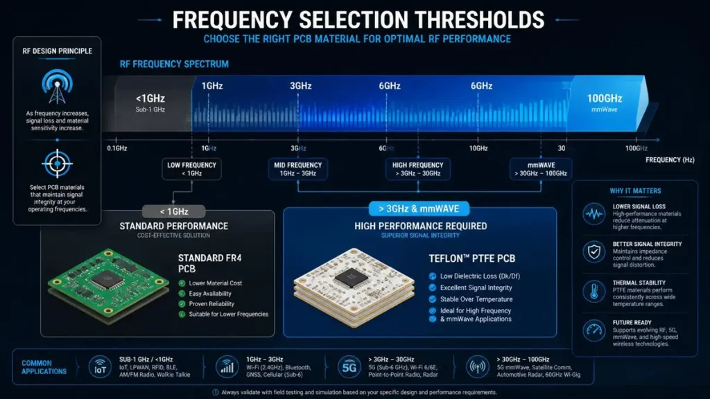
PCB Material Selection Framework: Frequency Spectrum Thresholds for PTFE vs FR4
Frequency-Driven Material Selection — GHz Thresholds for PTFE
The decision to move from FR4 to PTFE should begin with frequency analysis. As a practical rule:
- Below 1 GHz: FR4 is generally sufficient.
- 1–3 GHz: Evaluate FR4 against loss budgets carefully; high-Tg FR4 may suffice for less demanding applications.
- Above 3 GHz: PTFE becomes the pragmatic choice for most RF and microwave work.
- Above 10 GHz (mmWave): PTFE or ceramic-filled PTFE (e.g., Rogers RT/duroid series) is effectively mandatory.
Buyers should request that their engineering team provide the maximum operating frequency and acceptable insertion loss before issuing an RFQ. This prevents mismatched quotes and material disputes later in the program.
Signal Integrity Requirements and Impedance Control Demands
Projects requiring tight impedance tolerance (±5% or better), low VSWR, or minimal phase distortion demand the Dk stability of PTFE. If the design includes edge-coupled differential pairs, microstrip filters, or antenna feed networks, RF PCB impedance control material selection becomes non-negotiable. FR4’s Dk variance with temperature can shift impedance by 10% or more, causing return-loss failures in production.
Operating Environment — Temperature, Humidity, and Chemical Exposure
For outdoor infrastructure, marine systems, or aerospace applications, PTFE’s near-zero moisture absorption and broad chemical resistance eliminate the environmental derating that FR4 requires. A procurement specification that omits environmental testing criteria may pass prototype review yet fail field validation. Clarify IP ratings, thermal cycling profiles, and humidity exposure before locking material selection.
Project Budget Constraints and Total Cost of Ownership
Budget-constrained programs with loose RF requirements should stay on FR4. Programs where performance failure carries warranty, recall, or mission-failure costs should prioritize PTFE. The procurement question is not “Which is cheaper?” but “What does a field failure cost relative to the material premium?”
Teflon PCB Manufacturing Capabilities at Shenzhen Hongda Circuit Technology
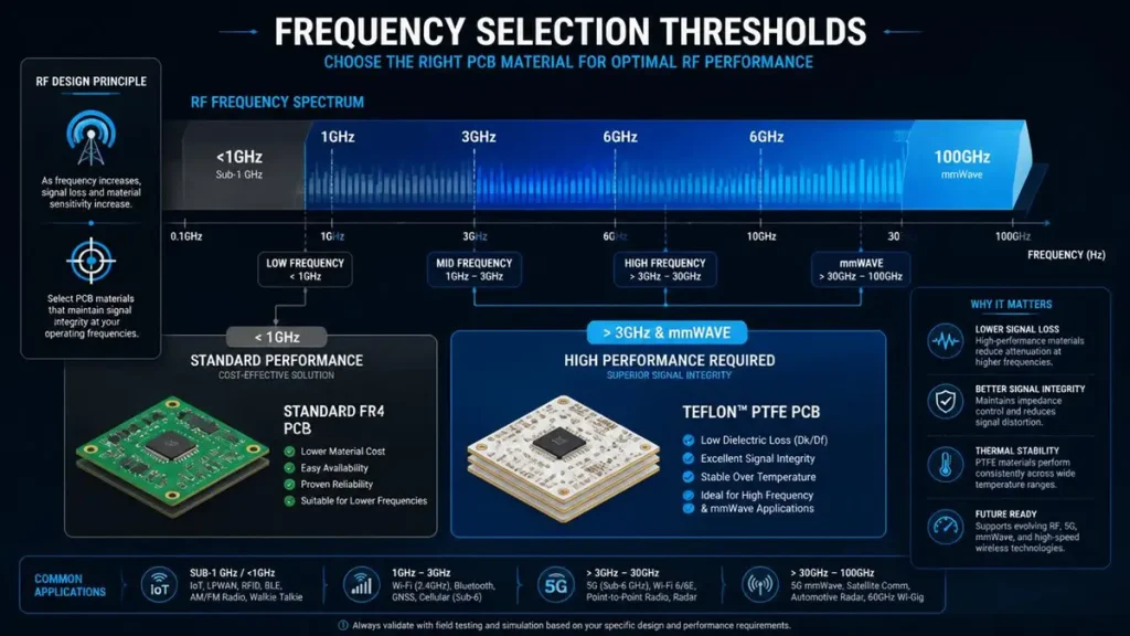
PCB Material Selection Framework: Frequency Spectrum Thresholds for PTFE vs FR4
Advanced PTFE PCB Fabrication Equipment and Process Control
At Shenzhen Hongda Circuit Technology Co., Ltd. (www.pcbkr.com), we have invested in fabrication infrastructure specifically tailored to the demands of high-frequency PCB manufacturing. Our facility operates precision CNC routing systems with optimized spindle speeds for PTFE soft-substrate drilling, minimizing fiber tear-out and maintaining hole-wall quality. We employ plasma treatment chambers for PTFE surface activation prior to electroless copper deposition, ensuring adhesion strength that meets IPC-Class 3 reliability standards.
For multilayer PTFE PCB stackup design considerations, our lamination presses support controlled heating ramps and pressure profiles that accommodate PTFE’s unique flow characteristics. We maintain dedicated tool sets and process lanes to prevent cross-contamination from standard epoxy-based workflows.
High-Frequency PCB DFM Support and Engineering Collaboration
Our engineering team provides pre-fabrication design-for-manufacturing (DFM) reviews focused on high-frequency PCB DFM requirements. We analyze trace geometry, ground-plane continuity, via transition structures, and solder mask selection to ensure that the fabricated board matches the simulated electrical model. For buyers, this means fewer prototype iterations and faster time-to-qualification.
Quality Assurance for RF PCB Production
Every PTFE board undergoes 100% electrical testing, impedance verification on coupon structures, and cross-sectional analysis for plating integrity. We maintain material traceability from laminate lot number through final inspection, supporting aerospace and defense procurement audit trails.
How to Evaluate a Teflon PCB Supplier — Procurement Checklist
Technical Capability Verification for PTFE PCB Manufacturers
Buyers should confirm that a prospective supplier has:
- Documented PTFE handling and plasma-activation processes.
- Controlled-impedance testing capability to the required tolerance.
- Experience with the specific PTFE grade specified (pure PTFE, glass-filled PTFE, or ceramic-filled PTFE).
- In-house cross-section and thermal-stress testing.
Lead Time, MOQ, and Supply Chain Reliability Assessment
PTFE PCB lead time and MOQ vary significantly by supplier. Pure PTFE materials often carry longer procurement lead times than ceramic-filled alternatives due to lower global inventory levels. Verify that your supplier maintains safety stock or has direct distributor relationships with laminate vendors such as Rogers, Taconic, or Arlon. Clarify MOQ thresholds early—some fabricators impose high minimums that conflict with prototype or NPI volumes.
Certifications and Quality Management Systems
While this guide avoids certification deep-dives, buyers should verify that the supplier operates under a recognized quality management system (ISO 9001 baseline) and can provide material certificates of conformance. For automotive or medical buyers, IATF 16949 or ISO 13485 alignment may be required depending on end-market regulations.
Teflon PCB vs FR4 PCB: Final Material Selection Guide
Application-Specific Recommendations
| Application Domain | Recommended Material | Rationale |
|---|---|---|
| 5G base station antennas | PTFE / ceramic-filled PTFE | Low loss at 3.5 GHz and 28 GHz; stable Dk |
| Satellite communication | Pure PTFE | Minimal outgassing; extreme thermal range |
| Automotive radar (77 GHz) | PTFE or Rogers RO3003 | Essential for mmWave signal integrity |
| General IoT / consumer electronics | FR4 | Cost-optimized; frequency demands are low |
| Industrial control systems | High-Tg FR4 | Adequate performance; mature supply chain |
| Microwave test fixtures | PTFE | Phase stability and repeatability critical |
Hybrid Stackup Options — Combining PTFE and FR4
Not every layer in a multilayer board carries RF signals. Hybrid constructions place PTFE on outer layers or specific signal layers while using FR4 for power and digital routing. This approach can reduce material cost by 30–50% compared to all-PTFE builds while preserving RF performance where it matters. Buyers should ask their fabricator about hybrid PTFE PCB stackup design considerations and DFM constraints before finalizing the stackup.
Frequently Asked Questions by PCB Procurement Professionals
Is Teflon PCB Better Than FR4 for Every Application?
No. Teflon PCB vs FR4 PCB which is better depends entirely on frequency, environment, and budget. Teflon (PTFE) is superior for high-frequency, low-loss, and thermally challenging applications. FR4 is the correct choice for general-purpose electronics where cost and lead time dominate the decision matrix. The “better” material is the one that meets the electrical specification at the lowest total cost of ownership.
What Are the Real-World Advantages of PTFE PCB in 5G and Microwave Systems?
The PTFE PCB advantages in 5G and microwave domains center on three metrics: (1) insertion loss below 0.001 dB/inch at 10 GHz, (2) Dk stability across −40°C to +150°C, and (3) moisture independence that prevents antenna detuning in outdoor enclosures. These properties directly translate into higher data rates, longer range, and reduced thermal management overhead.
Can FR4 Be Used for High-Frequency PCBs Above 3 GHz?
FR4 can be pushed into low-gigahertz territory with careful design, but its loss tangent and Dk instability create diminishing returns. Above 3 GHz, most RF engineers consider FR4 a risk rather than a solution. For production volumes where yield and repeatability matter, PTFE or ceramic-filled hydrocarbon materials are the pragmatic path.
How Much More Expensive Is Teflon PCB Compared to FR4, and Why?
Expect raw PTFE laminate to cost 5× to 10× standard FR4, with finished board premiums typically 3× to 5×. The drivers are material chemistry (fluoropolymer resin is more expensive than epoxy), lower fabrication yields (softer material is harder to drill and plate), and specialized process equipment (plasma treatment, controlled lamination). Volume production narrows the gap, but PTFE will never match FR4 pricing. The procurement justification must come from system-level performance gains or reliability improvements.
What Should I Look for When Selecting a PTFE PCB Manufacturer in China?
When evaluating a PTFE PCB manufacturer China, verify: (1) dedicated PTFE process lanes rather than shared FR4 lines, (2) plasma or sodium-etch surface preparation capability, (3) controlled-impedance testing to your tolerance, (4) direct laminate sourcing relationships (Rogers, Taconic, Arlon), and (5) engineering DFM support before fabrication release. Request cross-sectional photos and impedance reports from previous PTFE builds to validate capability claims.
Conclusion: Teflon PCB or FR4 PCB?
The Teflon PCB vs FR4 PCB decision is not about brand loyalty or material prestige. It is a procurement engineering calculation that weighs frequency requirements, signal integrity margins, environmental exposure, and total cost of ownership. PTFE delivers unmatched electrical performance for RF, microwave, and millimeter-wave systems. FR4 delivers economic efficiency for the vast majority of standard electronic applications.
At Shenzhen Hongda Circuit Technology Co., Ltd., we support procurement teams through every stage of this decision. Whether your program requires pure PTFE prototypes for satellite qualification or high-volume FR4 production for industrial controllers, our engineering and fabrication teams align material selection with your electrical, environmental, and budgetary constraints.
Need help selecting between Teflon PCB and FR4 PCB for your next program? Contact our RF engineering team at www.pcbkr.com to review your stackup, impedance requirements, and environmental specifications. We provide DFM feedback, material recommendations, and competitive quotations tailored to your procurement timeline.
About Author
David Chen https://www.linkedin.com/in/pcbcoming
David Chen boasts an extensive professional background in PCBA manufacturing, PCBA testing, and PCBA optimization, with specialized expertise in high-precision PCBA fault analysis and rigorous PCBA reliability testing. The author has worked with high-layer-count server PCB fabrication, ultra-low-loss backplane stackups, and thermo-mechanical reliability optimization for AI infrastructure projects involving 112G and 224G PAM4 architectures. Skilled in complex circuit design and cutting-edge advanced PCB manufacturing processes, he delivers solutions that elevate product durability and performance across industrial applications. His technical articles focusing on PCBA manufacturing workflows and testing methodologies are widely cited by industry peers, research institutions, and technical platforms, solidifying his reputation as a recognized technical authority in the global circuit board manufacturing sector.