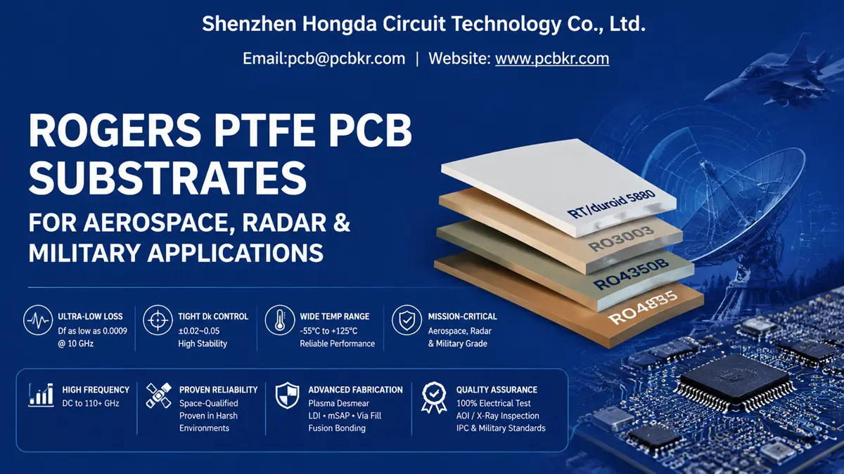
Rogers PTFE PCB Substrates for Aerospace, Radar & Military Applications
When a procurement team sources Rogers PTFE PCB substrates for radar front-ends, satellite transponders, or military-grade RF amplifiers, the stakes extend far beyond unit price. A single via failure in a phased-array antenna can ground an entire aerospace program. Signal loss in a 77 GHz automotive radar module can compromise collision-avoidance systems. Standard FR-4 simply dies above 10 GHz. PTFE-based laminates from Rogers Corporation—RT/duroid 5880, RO3003, RO4350B—are the only viable foundation for these designs, but fabricating them demands equipment and process knowledge that most PCB shops do not possess.
This guide walks through the material science, fabrication complexities, and quality verification protocols that separate qualified Rogers PCB material for military suppliers from generalist fabricators. Whether you are evaluating a new aerospace PCB substrate supplier or auditing an existing RF board vendor, the criteria below will sharpen your technical qualification process.
Why Rogers PTFE PCB Substrates Dominate Mission‑Critical RF Systems
Dielectric Performance That FR‑4 Cannot Match
At 28 GHz, a 10‑inch trace on FR‑4 loses approximately 20 dB. The same trace on Rogers RO4350B loses roughly 5 dB. That 4× improvement in insertion loss is the difference between a functional 5G mmWave base station and a paperweight. For military radar operating at 94 GHz, the gap becomes catastrophic—FR‑4 is unusable, while RT/duroid 5880 maintains signal integrity with a dissipation factor (Df) of 0.0009 at 10 GHz.
Rogers PTFE PCB substrates deliver three non‑negotiable properties for high‑frequency designs:
- Stable Dielectric Constant (Dk): Tight tolerances (±0.02–0.05) ensure 50 Ω impedance control across temperature swings from −55 °C to +125 °C.
- Ultra‑Low Dissipation Factor (Df): PTFE‑based materials minimize energy conversion to heat, preserving signal amplitude in long feed networks.
- CTE Matching to Copper: Z‑axis CTE values in the 24 ppm/°C range (for ceramic‑filled PTFE) reduce plated‑through‑hole (PTH) barrel cracking during thermal cycling.
Material Grades: RT/duroid 5880 vs RO3000 vs RO4000 Series
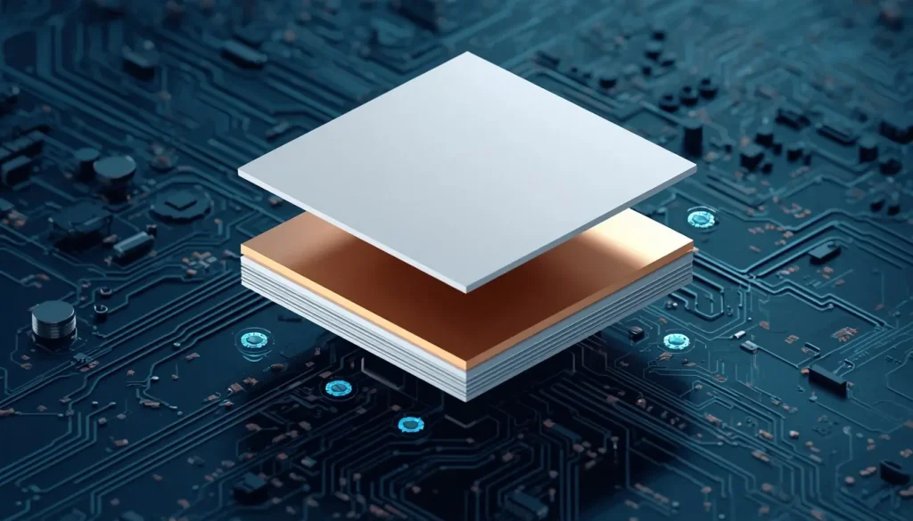
3D exploded view illustrating the high-frequency laminate stack-up structure, featuring Rogers PTFE substrates and copper-clad layers.
Not every Rogers laminate is PTFE‑based, and confusing the families is a common source of procurement errors.
| Material Series | Base Chemistry | Dk @ 10 GHz | Df @ 10 GHz | Fabrication Complexity | Typical Application |
|---|---|---|---|---|---|
| RT/duroid 5880 | Glass microfiber PTFE | 2.20 ± 0.02 | 0.0009 | High—plasma desmear mandatory | Satellite comms, military EW, 110 GHz+ instrumentation |
| RT/duroid 6002 | Ceramic‑filled PTFE | 2.94 ± 0.04 | 0.0012 | High—plasma + high‑T lamination | Aerospace radar, stripline couplers |
| RO3003 | Ceramic‑filled PTFE | 3.00 ± 0.04 | 0.0010 | High—plasma desmear required | 77 GHz automotive radar, mmWave 5G |
| RO4350B | Hydrocarbon ceramic | 3.48 ± 0.05 | 0.0037 | Moderate—FR‑4 compatible | Sub‑6 GHz 5G, Wi‑Fi 6E, base station power amps |
| RO4835 | Hydrocarbon ceramic | 3.38 ± 0.05 | 0.0031 | Moderate—FR‑4 compatible | 5G small cells, automotive radar |
PTFE‑based materials (RT/duroid and RO3000 series) require dedicated fabrication lines. Hydrocarbon‑ceramic RO4000 materials process on standard FR‑4 equipment but sacrifice the absolute lowest loss figures. For military grade PCB substrate applications above 40 GHz, PTFE is the only rational choice.
Rogers PTFE PCB Applications in High‑Barrier Vertical Markets
Radar Systems & Electronic Warfare
Active electronically scanned arrays (AESA) and synthetic aperture radar (SAR) platforms operate at 35 GHz, 94 GHz, and beyond. At these frequencies, even micro‑roughness on copper traces radiates energy as loss. RT/duroid 5880’s ultra‑low Df and isotropic Dk stability allow beamforming networks to maintain phase coherence across hundreds of radiating elements. Military electronic warfare (EW) systems also favor PTFE substrates for their low passive intermodulation (PIM), which prevents self‑jamming in dense RF environments.
Aerospace & Satellite Communication
Satellite payloads face vacuum outgassing constraints, extreme thermal cycling, and zero‑failure tolerance. PTFE laminates with glass microfiber reinforcement (RT/duroid 5880) have flown on space‑qualified hardware for decades. Their low moisture absorption (< 0.02%) prevents Dk drift in humid launch environments, and fusion‑bonded multilayer constructions eliminate adhesive outgassing risks.
Military Communications & Defense Electronics
Manpack radios, UAV datalinks, and shipboard communications equipment demand Rogers PCB material for military use that survives MIL‑STD‑810 shock and vibration profiles. Hybrid stack‑ups—Rogers PTFE cores on RF layers bonded to high‑Tg FR‑4 for digital control—reduce material cost by 30–50% while preserving RF performance where it counts. The key is qualifying the bondply system (Rogers 2929 or FEP film) and validating CTE compatibility across the full temperature range.
5G Base Stations & mmWave Infrastructure
While not strictly military, defense‑adjacent telecom infrastructure shares the same material requirements. 28 GHz and 39 GHz mmWave base stations use Rogers RO3003 and RO4835 for massive MIMO antenna arrays. The thermal conductivity of ceramic‑filled PTFE (0.50–0.79 W/m·K) helps dissipate heat from GaN power amplifiers in outdoor enclosures.
PTFE PCB Fabrication Challenges & Advanced Manufacturing Solutions
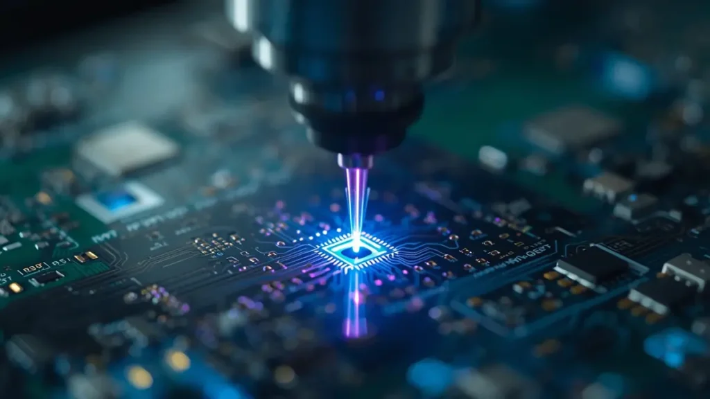
High-precision laser drilling operation on Rogers PTFE substrate for microvia creation, utilizing advanced UV/CO2 laser equipment.
The PTFE Processing Gap: Why Generalist Fabricators Fail
PTFE is chemically inert. Standard permanganate desmear—the workhorse process for FR‑4—does not touch PTFE hole walls. Without proper surface activation, electroless copper will not adhere, and vias fail pull‑strength testing. Generalist PCB shops often treat Rogers laminates as “premium FR‑4,” resulting in delamination, lifted pads, and intermittent opens that surface only after field deployment.
Three process categories separate qualified Rogers PTFE PCB manufacturers from pretenders:
- Surface activation before lamination and plating
- Modified drilling and routing parameters for soft substrates
- High‑temperature lamination cycles (380–400 °C vs. 175–185 °C for FR‑4)
Precision Drilling & Hole‑Wall Preparation for Soft Laminates
PTFE’s low rigidity causes material smearing during mechanical drilling. Carbide drills with 130° included lip angles, surface speeds of 150–250 SFM, and reduced stack heights (≤ 0.240 inches) are mandatory. Undercut‑style drill geometries minimize redeposited smear. For microvias below 150 μm, UV/CO₂ hybrid laser drilling provides cleaner ablation without mechanical deformation.
At Shenzhen Hongda Circuit Technology Co., Ltd., our drilling line runs Mitsubishi UV/CO₂ laser systems alongside CNC spindles with automated condition monitoring. This dual capability lets us switch between mechanical and laser drilling based on via diameter and layer count, optimizing cost and quality for each Rogers high frequency PCB project.
Plasma Activation & Metallization for Reliable PTH
Plasma treatment is the industry‑standard method for PTFE surface activation. A vacuum chamber exposes the substrate to ionized gas—typically O₂, CF₄, N₂, or H₂/N₂ mixtures—which micro‑etches the hole walls and creates anchor points for copper adhesion.
The process parameters matter. A validated cycle for RT/duroid 5880 might use:
- Stage 1: O₂ 50% / He 50% at 4,300 W RF power for 10 minutes
- Stage 2: He 100% at 2,575 W RF power for 15 minutes
- Endpoint temperature: 175 °F (79 °C)
After plasma activation, electroless copper deposition follows immediately. Delaying metallization by even a few hours allows PTFE to revert to its inert state, destroying adhesion. Hongda Circuit operates inline plasma‑to‑plating workflows that eliminate this risk.
High‑Temperature Lamination & Thermal Management
PTFE multilayer boards bond at 380–400 °C in vacuum presses—temperatures that would destroy standard FR‑4. This requires specialized press equipment with precise heating and cooling ramps to prevent warpage. For hybrid Rogers/FR‑4 stack‑ups, the lamination cycle must balance the distinct glass‑transition temperatures of hydrocarbon/ceramic cores and epoxy prepreg.
Thermal management extends beyond lamination. High‑power RF amplifiers on PTFE substrates generate localized heat fluxes that standard vias cannot extract. Thermally conductive Rogers TC350 or TC600 (up to 1.0 W/m·K) replace standard PTFE in these zones, or metal‑core inserts provide direct heat sinking. Our engineering team models thermal gradients during DFM review, identifying hotspots before tooling begins.
ENIG Surface Finish for High‑Frequency Reliability
For Rogers PCB substrate boards destined for aerospace or military connectors, Electroless Nickel Immersion Gold (ENIG) remains the dominant finish. It delivers a flat, solderable surface with excellent shelf life and corrosion resistance. For ultra‑high‑frequency applications where even nickel skin effect adds loss, immersion silver provides lower RF resistance but requires tighter storage controls. Hongda Circuit qualifies both finishes under IPC‑4552 and IPC‑4553, with thickness verification by XRF on every panel.
Quality Assurance & Procurement Trust Signals for Defense Buyers
IPC‑6012 Class 3, AS9100 & ISO 13485 Certifications
A supplier’s certificate wall tells only part of the story. What matters is how those standards translate to daily process control.
- IPC‑6012 Class 3: Sets acceptance criteria for high‑reliability boards—stricter annular ring requirements, copper plating thickness minimums, and dielectric withstand voltages. For military grade PCB substrate orders, Class 3 is non‑negotiable.
- AS9100: The aerospace quality management standard that extends ISO 9001 with risk management, configuration control, and counterfeit parts prevention. Any aerospace PCB substrate supplier without current AS9100 registration should be disqualified from flight‑hardware bids.
- ISO 13485: While medically focused, its traceability and process‑validation requirements align closely with defense procurement expectations for lot control and documentation.
Full‑Board X‑Ray Inspection & Impedance Validation
Visual inspection and AOI catch surface defects. They miss internal delamination, barrel cracks, and plating voids. For multilayer Rogers PTFE PCBs, full‑board automated X‑ray inspection (AXI) verifies every via barrel and internal pad alignment. Hongda Circuit uses Nordson DAGE X‑ray systems to screen 100% of high‑reliability panels, not just coupon sections.
Impedance control is equally critical. A 50 Ω microstrip on RT/duroid 5880 tolerates minimal deviation—±5% is typical, but radar designs often demand ±3%. Time‑domain reflectometry (TDR) testing on every panel, with copper‑roughness correction factored into field‑solver models, ensures compliance. We provide impedance test reports with each shipment, traceable to panel serial numbers.
Material Traceability & Lot Control
Defense programs require complete supply chain transparency. Every sheet of Rogers laminate must map to a manufacturer lot number, Dk/Df test report, and certificate of conformance. Hongda Circuit maintains an AI‑driven ERP tracking system that links raw material lots to finished panel serial numbers, achieving >95% on‑time delivery while preserving full traceability for audit purposes.
Shenzhen Hongda Circuit: Your Rogers PTFE PCB Manufacturing Partner
Advanced Equipment for PTFE & Hybrid Stackups
Shenzhen Hongda Circuit Technology Co., Ltd. (PCBKR) operates a dedicated high‑frequency fabrication line built specifically for Rogers and Taconic laminates. Our 2026 equipment portfolio includes:
- SCREEN Ledia LDI Exposure: Laser direct imaging eliminates phototool distortion, achieving ±8 μm registration accuracy on PTFE multilayers.
- Mitsubishi UV/CO₂ Laser Drilling: 50 μm microvia capability for Any‑Layer HDI on hybrid RF/digital stack‑ups.
- LAUFFER High‑Temperature Lamination: Vacuum presses rated to 420 °C with programmable heating ramps for PTFE fusion bonding.
- Inline Plasma Desmear: CF₄/O₂ plasma system with automated process timing, feeding directly into electroless copper.
- Nordson DAGE X‑Ray & TDR: Full‑board internal inspection and impedance validation to ±5%.
We stock Rogers RT/duroid 5880, RO3003, RO4350B, and RO4835 laminates for quick‑turn prototypes, reducing procurement lead times from weeks to days.
Engineering‑Led DFM for RF Performance
Our RF engineering team reviews every stack‑up before tooling. We validate:
- Impedance continuity at dielectric transitions in hybrid Rogers/FR‑4 designs
- Bondply compatibility and CTE mismatch risks
- Thermal via placement for high‑power GaN amplifier stages
- Signal layer assignments that minimize cross‑talk in dense radar feed networks
This collaborative DFM workflow cuts prototype iterations by 30% and eliminates surprises during first‑article inspection.
Rapid Prototyping to Volume Production
Whether you need five panels for a satellite payload prototype or five thousand for a radar production run, Hongda Circuit scales without process changes. Our quick‑turn cell delivers Rogers PTFE prototypes in 7–10 days, while the volume line maintains IPC Class 3 process discipline at scale. Every order—regardless of quantity—ships with material certifications, impedance reports, and microsection photographs.
Frequently Asked Questions: Rogers PTFE PCB Procurement
How do I verify that a PCB manufacturer can actually process Rogers PTFE laminates, not just quote them?
Request microsection photographs of past PTFE multilayer boards, specifically showing hole‑wall copper adhesion after thermal stress testing. Ask for plasma process validation data and whether they operate inline plasma‑to‑plating or batch treatment. A qualified Rogers PTFE PCB manufacturer will provide Dk/Df material certificates, impedance test reports, and IPC‑6012 Class 3 qualification records without hesitation. If they treat PTFE as “premium FR‑4,” find another supplier.
What is the real cost difference between pure Rogers PTFE and Rogers/FR‑4 hybrid stack‑ups?
Pure PTFE multilayers typically cost 6–8× more than standard FR‑4. A well‑designed hybrid stack‑up—using Rogers PTFE only on RF signal layers and high‑Tg FR‑4 for digital/power layers—reduces material cost by 30–50% while preserving RF performance. The trade‑off is increased engineering complexity in lamination and impedance modeling. For most radar and 5G base station designs, hybrid constructions offer the optimal balance.
Why is plasma treatment mandatory for PTFE but not for RO4350B?
RO4350B is a hydrocarbon‑ceramic composite, not PTFE. Its surface energy supports standard chemical desmear and direct metallization. PTFE is chemically inert—standard permanganate solutions cannot etch it. Without plasma activation or sodium naphthalene treatment, electroless copper will not bond to PTFE hole walls, resulting in via barrel separation and field failures. Plasma is the preferred mass‑production method because it is dry, repeatable, and environmentally cleaner than wet chemistry.
Which certifications should I demand for aerospace and military Rogers PCB orders?
Minimum requirements: IPC‑6012 Class 3 for product acceptance, AS9100 for aerospace quality management, and ISO 9001 as a baseline. For U.S. defense programs, MIL‑PRF‑31032 and ITAR registration are standard. Medical‑adjacent suppliers with ISO 13485 often demonstrate process‑validation discipline that transfers well to military traceability requirements. Always verify certificate expiry dates and scope—some suppliers claim “ISO certified” while excluding high‑frequency laminate processing from their audit scope.
How does Hongda Circuit handle material traceability for defense supply chains?
Every Rogers laminate sheet entering our facility is logged with manufacturer lot number, Dk/Df test data, and certificate of conformance. Our AI‑driven ERP system tracks these lots through drilling, plasma treatment, lamination, and final test, linking raw material to finished panel serial numbers. Shipment documentation includes full material certifications, impedance test reports, microsection photographs, and X‑ray inspection records. This level of documentation supports AS9100 audit trails and defense program qualification requirements.
Ready to qualify your next Rogers PTFE PCB project? Contact Shenzhen Hongda Circuit Technology Co., Ltd. at www.pcbkr.com for a free DFM review, stack‑up optimization, and 24‑hour quotation on RT/duroid, RO3000, and hybrid RF designs.
About Author
David Chen https://www.linkedin.com/in/pcbcoming
David Chen boasts an extensive professional background in PCBA manufacturing, PCBA testing, and PCBA optimization, with specialized expertise in high-precision PCBA fault analysis and rigorous PCBA reliability testing. The author has worked with high-layer-count server PCB fabrication, ultra-low-loss backplane stackups, and thermo-mechanical reliability optimization for AI infrastructure projects involving 112G and 224G PAM4 architectures. Skilled in complex circuit design and cutting-edge advanced PCB manufacturing processes, he delivers solutions that elevate product durability and performance across industrial applications. His technical articles focusing on PCBA manufacturing workflows and testing methodologies are widely cited by industry peers, research institutions, and technical platforms, solidifying his reputation as a recognized technical authority in the global circuit board manufacturing sector.