How Do You Choose a Reliable Thermostat PCB Manufacturer for OEM Production?
Thermostat PCB manufacturing and PCBA assembly for OEMs
Choosing a thermostat PCB manufacturer is not simply a matter of comparing board prices. OEM buyers need a supplier that can manufacture the required circuit structure, assemble components consistently, manage sourcing risks, and agree on inspection and functional-test requirements before production begins. For HVAC controls, smart thermostats, heating equipment, and refrigeration systems, the right manufacturing partner should review the design, identify production risks, and support the transition from prototype to repeatable production.
Shenzhen Hongda Circuit Technology Co., Ltd. (PCBKR) provides PCB fabrication, engineering support, and PCBA services for electronic product developers and OEM buyers. Send your board files, bill of materials (BOM), target quantity, and testing requirements to pcb@pcbkr.com for a project-specific manufacturing review and quotation.
What Should OEM Buyers Look for in a Thermostat PCB Manufacturer?
A qualified thermostat PCB supplier should be evaluated against the actual design, production volume, component requirements, and quality plan—not only its advertised minimum line width or lowest unit price.
Thermostat control boards vary significantly. A basic thermostat interface may require a conventional PCB, while a smart thermostat can include a microcontroller, temperature sensor, wireless connectivity, display, switching circuitry, and a low-voltage power supply. HVAC or heating applications may also involve relays or mains-connected circuitry, which introduce additional electrical and safety considerations.
Before selecting a supplier, confirm the following:
| Procurement criterion | What buyers should verify |
|---|---|
| PCB fabrication | Layer count, board dimensions, thickness, copper weight, surface finish, and material compatibility |
| Component assembly | SMT, through-hole assembly, mixed technology, package sizes, and connector requirements |
| Component sourcing | Approved manufacturer part numbers, availability, traceability, and substitution approval |
| Inspection | AOI, X-ray where applicable, electrical testing, and defined acceptance criteria |
| Functional verification | Whether power-up, sensor simulation, relay operation, calibration, or other tests are included |
| Production readiness | Revision control, first-article approval, process documentation, and repeat-order consistency |
| Commercial terms | Prototype and production pricing, tooling, lead time, minimum order quantity, and shipping scope |
A supplier may have capable PCB fabrication equipment but still be unsuitable if its assembly, sourcing, or testing scope does not match the product. Buyers should assess the entire manufacturing plan before issuing a production purchase order.
For designs that need a manufacturability review before quotation, buyers can also explore our PCB design and engineering support to clarify fabrication constraints and production requirements.
Which Thermostat PCB Architecture Fits Your Product?
The appropriate PCB architecture depends on the thermostat’s electrical design, enclosure, operating environment, and production requirements. A manufacturer should review the actual design rather than assume every thermostat needs HDI or advanced fine-line processing.
| Thermostat application | Typical PCB considerations | Manufacturing review priorities |
|---|---|---|
| Basic room thermostat | Sensor interface, control circuitry, connectors | Board cost, stable assembly, electrical continuity |
| Digital thermostat | MCU, display, buttons, sensor input | Component placement, routing, solder quality |
| Smart thermostat | MCU, wireless module, power management, compact layout | RF-module integration, power integrity, thermal separation |
| HVAC control board | Relay drivers, inputs and outputs, low-voltage control | Connector robustness, switching loads, electrical safety |
| Heating or refrigeration controller | Temperature sensing, switching, environmental exposure | Sensor accuracy chain, thermal effects, component ratings |
| Industrial temperature controller | Noise-sensitive measurement, control outputs, demanding operating conditions | EMC-related design review, material suitability, test coverage |
When does a thermostat need HDI or fine-line PCB manufacturing?
HDI and fine-line processing may be useful when a smart thermostat has a compact footprint, dense component placement, fine-pitch packages, or multiple functional blocks competing for board space. They are not automatically necessary for a conventional thermostat controller.
PCBKR’s manufacturing portfolio includes SCREEN Ledia laser direct imaging (LDI), Mitsubishi UV/CO₂ laser drilling, mSAP processing, and controlled vacuum lamination. These technologies can support appropriate high-density designs, but the required process should be selected from the actual Gerber data, stack-up, component pitch, and design rules.
For many thermostat products, a well-designed conventional multilayer PCB will be more economical than an unnecessarily complex HDI construction. The engineering objective is to meet the product requirements with a manufacturable design—not to use the most advanced process simply because it is available.
How Do PCB Materials, Copper Weight, and Layout Affect Thermostat Reliability?
PCB material and layout influence manufacturability, heat distribution, electrical noise, and long-term structural stability. However, the PCB alone does not determine the complete thermostat’s temperature accuracy or service life.
How should buyers specify the PCB material?
FR-4 is a common starting point for many thermostat control boards. The final material selection should consider operating temperature, board thickness, mechanical requirements, soldering process, component power dissipation, and any applicable product qualification requirements.
A higher-Tg material may be appropriate for some elevated-temperature or demanding assembly conditions, but it should be selected based on the expected thermal profile and reliability requirements rather than used as a blanket upgrade.
For a quotation, specify the required laminate grade if it is fixed by the design. If it is not fixed, ask the manufacturer to propose a suitable material for engineering approval.
How should copper weight and power routing be reviewed?
Copper thickness, trace geometry, via structure, connector ratings, and temperature rise must be considered together. A relay-controlled heating system or a board switching an external load may require more careful power-path review than a low-current sensor interface.
Buyers should provide expected current, peak current, switching conditions, connector specifications, and allowable temperature rise where these are defined. The manufacturer can then assess fabrication feasibility and identify questions requiring the design engineer’s decision.
PCBKR’s manufacturing portfolio includes conventional and heavy-copper PCB processes. Heavy copper should be considered only where the electrical and thermal design justifies it; it is not a substitute for appropriate trace sizing, component selection, or thermal validation.
How can PCB manufacturing affect temperature measurement accuracy?
A thermostat’s measurement accuracy depends on the complete sensing and control chain, including the sensor, reference components, analog front end, ADC, firmware, calibration, enclosure, and local heat sources.
PCB layout and assembly can contribute to measurement error if they introduce unwanted thermal coupling, poor grounding, supply noise, contamination, or inconsistent component placement. For example, placing a temperature sensor close to a heat-producing regulator may cause the sensor to measure local board heating rather than the intended ambient temperature.
A useful engineering review should examine:
- Sensor placement relative to relays, regulators, displays, and other heat-producing components.
- Routing and grounding around low-level analog signals.
- Component tolerances and the reference-voltage architecture.
- Soldering and assembly effects on sensitive components.
- Calibration requirements and the test method used to verify measurement accuracy.
Advanced imaging and inspection equipment helps control board fabrication and assembly quality, but it cannot independently guarantee system-level temperature accuracy. Calibration and functional verification must be separately defined.
What Should Buyers Check in Thermostat AC-DC Power and Relay Circuits?
If a thermostat PCB connects to mains power or switches hazardous voltages, the procurement review should include electrical separation, insulation design, component ratings, and the applicable product safety requirements. These issues do not apply identically to every low-voltage thermostat, so the circuit architecture must be established first.
How should primary-to-secondary isolation be assessed?
For a mains-powered design, the primary and secondary circuits may require specified creepage and clearance distances, insulation barriers, slots, and suitable component ratings. The required distances depend on factors such as working voltage, insulation category, pollution degree, material group, altitude, and the applicable safety standard.
There is no single clearance value that is appropriate for every thermostat PCB. The OEM’s electrical safety requirements and the relevant product standard should govern the design review.
The manufacturer should identify apparent fabrication concerns and confirm which checks are included in its scope. Final safety compliance must be established through the applicable design assessment and verification process—not inferred from the presence of a slot or from a generic PCB capability statement.
How should relay switching and electromagnetic interference be reviewed?
Relay contacts and coils can introduce switching transients, while motors, compressors, and other connected loads can create electrical disturbances. The correct mitigation depends on the load, switching frequency, circuit topology, grounding, and protection components.
The design review should check:
- Separation of noisy switching paths from sensitive sensor and analog circuits.
- Relay, connector, trace, and via suitability for the specified load.
- The intended placement of suppression components and power filtering.
- Return-current paths and the effect of switching noise on sensor readings.
- The required EMC verification plan for the finished product.
PCB manufacturing controls can help reproduce the intended layout and construction, but EMC performance depends on the full design and product configuration. Buyers should not treat an AOI pass or electrical continuity test as proof of EMC compliance.
How Should Thermostat PCBA Quality and Functional Testing Be Defined?
A reliable thermostat PCBA inspection plan specifies which defects each method is intended to detect and which results will be recorded. Visual inspection alone is not sufficient for every assembly, particularly when the board contains hidden solder joints or requires application-specific functional verification.
| Inspection or test | What it can help verify | Important limitation |
|---|---|---|
| AOI | Visible solder and component-placement defects | Does not verify all hidden joints or system functions |
| X-ray | Hidden solder joints and selected internal assembly features | Applicability depends on package and defect type |
| Flying-probe or other electrical test | Specified opens, shorts, continuity, and isolation | Does not prove correct thermostat operation |
| Power-up test | Basic powered operation under defined conditions | Requires an agreed setup and acceptance limits |
| Sensor simulation | Response to defined sensor inputs | Requires a specified input range and expected output |
| Relay functional test | Switching behavior under an agreed test condition | Does not automatically establish lifetime or safety compliance |
| Calibration or temperature test | Measurement performance against defined references | Must specify tolerance, conditions, and method |
PCBKR’s published capability information includes 3D AOI, X-ray inspection, and flying-probe testing. The exact methods available for a thermostat project, along with their coverage and reporting, should be confirmed during quotation.
For functional tests, the OEM should define the expected behavior, test points, firmware version, operating range, pass/fail limits, and whether a dedicated fixture is needed. If environmental cycling, insulation testing, relay-load testing, or formal product certification is required, include it explicitly in the RFQ rather than assuming it is included in standard assembly.
If your project requires board fabrication and component assembly under one coordinated scope, learn more about our turnkey PCB assembly service.
How Can PCBKR’s Manufacturing Equipment Support Thermostat PCB Projects?
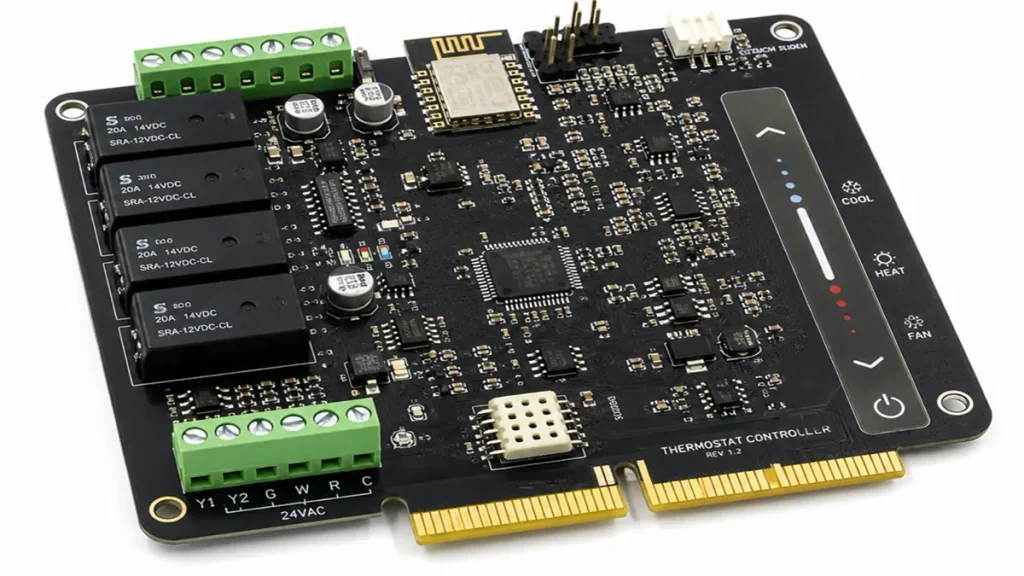
Thermostat PCB manufacturing with precision circuit imaging, multilayer fabrication and PCBA inspection
The value of manufacturing technology is its fit with the board’s actual requirements. PCBKR’s equipment portfolio offers several relevant process options for projects requiring controlled circuit imaging, multilayer construction, dense interconnections, or documented inspection.
| PCBKR technology or equipment | Potential relevance to thermostat projects |
|---|---|
| SCREEN Ledia LDI | Supports precise circuit imaging and registration for suitable PCB constructions |
| Mitsubishi UV/CO₂ laser drilling | Supports laser-drilled microvias in designs that require HDI interconnection |
| LAUFFER vacuum lamination | Supports multilayer fabrication using a controlled lamination process |
| mSAP processing | Provides a fine-line manufacturing option for appropriate high-density layouts |
| 3D AOI | Supports inspection of visible assembly features and solder conditions |
| X-ray inspection | Supports inspection of selected hidden joints and assembly structures |
| Flying-probe testing | Supports electrical verification according to the defined test program |
These capabilities are not all required for every thermostat. A cost-sensitive room thermostat may need a conventional board and a straightforward assembly plan; a compact smart thermostat may require denser routing and more demanding assembly inspection.
The supplier qualification discussion should therefore focus on the equipment and process controls relevant to the specific design. Buyers should request confirmation of the applicable process window, inspection coverage, and available reports rather than relying solely on headline minimum feature sizes.
For projects requiring both board fabrication and assembly, PCBKR can review the fabrication data and PCBA requirements together, subject to the agreed scope, component availability, and project specifications.
How Can Buyers Compare Thermostat PCB Manufacturers Fairly?
A meaningful supplier comparison uses the same technical package, test scope, and commercial assumptions for every bidder. Otherwise, a lower quotation may simply exclude services that another supplier has included.
Use the following checklist during supplier qualification:
- Engineering review: Does the supplier identify missing specifications and manufacturing risks before production?
- Fabrication capability: Can it meet the specified layer count, material, copper weight, tolerances, and board geometry?
- Assembly capability: Can it place and solder the required packages, connectors, and mixed-technology components?
- Sourcing control: Are component manufacturer part numbers, approved alternatives, and traceability expectations documented?
- Inspection scope: Are AOI, X-ray, electrical tests, and functional checks clearly defined?
- Production control: How are design revisions, BOM changes, nonconformities, and repeat orders managed?
- Quotation transparency: Are tooling, test fixtures, programming, component sourcing, packaging, and shipping included or excluded explicitly?
For a new design, ask what evidence the supplier can provide at the first-article stage. Depending on the project, this might include a fabrication inspection report, electrical test results, assembly inspection records, and functional-test data against the OEM’s approved criteria.
Do not treat an equipment list, an ISO certificate, or a general quality statement as proof that a particular thermostat design has already been validated. Qualification evidence should match the product, process, and requirements being purchased.
What Determines Thermostat PCB Cost and Lead Time?
Thermostat PCB cost and lead time depend on board construction, order quantity, assembly complexity, component sourcing, inspection requirements, and delivery conditions. A bare-board quote and a fully assembled, tested PCBA quote are not directly comparable.
The main cost drivers include:
- Board size, layer count, laminate specification, copper weight, and surface finish.
- Fine-pitch components, special assembly requirements, and double-sided placement.
- BOM availability, minimum purchasing quantities, and approved-component restrictions.
- Test fixtures, programming, calibration, and application-specific functional tests.
- Prototype quantity versus expected production volume.
- Required documentation, packaging, and shipping arrangements.
For lead-time planning, distinguish PCB fabrication time, component procurement time, assembly time, and testing time. A board may be easy to fabricate but delayed by a long-lead component or an unfinished test fixture.
Component availability can affect both quotation accuracy and delivery schedules. Review our PCB component sourcing service for more information about BOM review and supply-chain planning.
To obtain a useful quotation, provide the target delivery date and identify any components that are customer-supplied or subject to strict sourcing restrictions. If the design is still changing, ask for a feasibility review before treating an initial estimate as a production commitment.
What Information Should You Include in a Thermostat PCB RFQ?
A complete RFQ reduces clarification cycles and helps suppliers quote the same scope. If some engineering decisions are still open, mark them as pending rather than leaving them ambiguous.
For bare PCB fabrication, provide:
- Gerber files and drill data, or another mutually accepted manufacturing-data format.
- Board outline, dimensions, layer count, thickness, and stack-up.
- Copper weight, material requirements, surface finish, and solder-mask specifications.
- Controlled-impedance or special tolerance requirements, if applicable.
- Quantity for prototypes and production, plus expected repeat-order volume.
For PCBA, also provide:
- BOM with manufacturer part numbers, quantities, packages, and approved alternatives.
- Pick-and-place data and assembly drawings.
- Component polarity, connector orientation, and special handling notes.
- Firmware or programming requirements, where applicable.
- Inspection plan, functional-test procedure, acceptance limits, and reporting needs.
- Target schedule, packaging requirements, and shipping destination.
If the thermostat uses mains power, include the applicable safety requirements and the design information needed to review isolation and switching circuitry. If temperature accuracy is a product requirement, provide the measurement range, tolerance, calibration method, and test conditions.
For new thermostat designs that need engineering review before moving from prototype builds toward repeat production, explore our NPI PCB prototype manufacturing service.
Request a Thermostat PCB Quote from PCBKR
Send your available fabrication data, BOM, target quantities, and required testing scope to pcb@pcbkr.com. PCBKR can review the proposed PCB and PCBA manufacturing requirements and identify the information needed for a project-specific quotation.
What Do Buyers Ask When Searching for a Thermostat PCB Supplier?
How do I choose a reliable thermostat PCB manufacturer?
Compare the supplier’s fabrication and assembly capability against your actual design, then confirm component sourcing controls, inspection methods, test coverage, revision management, and production documentation. Request project-relevant evidence rather than relying on a generic capability list or the lowest unit price.
What information is required to get a thermostat PCB quote?
For bare PCB fabrication, provide Gerber and drill data, stack-up, board dimensions, material, copper weight, surface finish, quantity, and special tolerances. For PCBA, add the BOM, placement file, assembly drawings, sourcing preferences, test requirements, and target schedule.
Can one supplier manufacture and assemble custom thermostat PCBs?
A one-stop supplier can coordinate PCB fabrication and assembly under a shared project scope, reducing handoffs between separate vendors. Confirm whether component procurement, SMT and through-hole assembly, inspection, programming, and functional testing are included in the specific quotation.
How do you test a thermostat PCBA before mass production?
The test plan should match the design. It may include AOI, X-ray for applicable hidden joints, electrical testing, powered functional checks, sensor simulation, relay operation, or calibration against defined limits. The OEM and supplier should agree on test conditions, pass/fail criteria, and reports before production begins.
How much does a custom thermostat PCB cost?
There is no reliable universal price because cost depends on board construction, order quantity, component availability, assembly complexity, test scope, and delivery requirements. Send the fabrication files and BOM with prototype and production quantities so suppliers can quote comparable scopes.
Contact: Shenzhen Hongda Circuit Technology Co., Ltd.
Email: pcb@pcbkr.com
Website: https://www.pcbkr.com/
All manufacturing and testing requirements should be confirmed against the specific design and quotation. Product-level safety, EMC, calibration, and reliability claims require the relevant design validation and test evidence.
About Author
David Chen LinkedIn Profile
David Chen is a Senior RF/PCB Process Engineer at Shenzhen Hongda Circuit Technology Co., Ltd., with over 12 years of experience in high-frequency PCB fabrication, impedance-controlled stack-up design, and Rogers/PTFE laminate processing. He also boasts an extensive professional background in PCBA manufacturing, PCBA testing, and PCBA optimization, with specialized expertise in high-precision PCBA fault analysis and rigorous PCBA reliability testing. The author has worked with high-layer-count server PCB fabrication, ultra-low-loss backplane stackups, and thermo-mechanical reliability optimization for AI infrastructure projects involving 112G and 224G PAM4 architectures. Skilled in complex circuit design and cutting-edge advanced PCB manufacturing processes, he delivers solutions that elevate product durability and performance across industrial applications. His technical articles focusing on PCBA manufacturing workflows and testing methodologies are widely cited by industry peers and technical platforms, and have gained attention and recognition from industry colleagues.