How Do You Choose a Reliable Robot Vacuum Cleaner Mainboard PCBA Manufacturer?
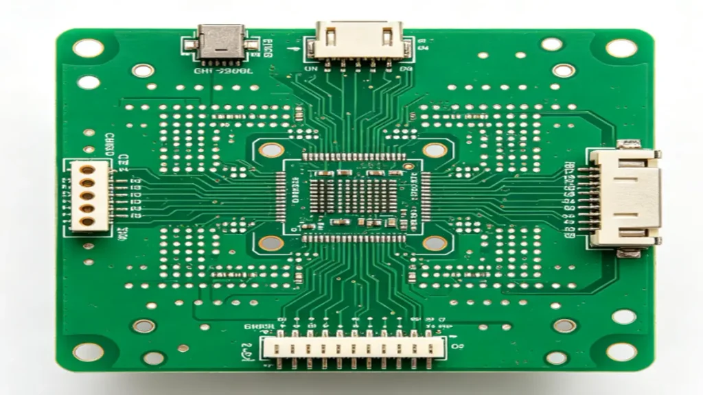
Base Material: FR-4 (High-Tg FR-4 optional)
Number of Layers: 2–8 Layers
Board Thickness: 0.8–1.6 mm
Copper Thickness: 1–2 oz (35–70 μm)
Minimum Trace Width / Spacing: 4/4 mil (0.10/0.10 mm)
Minimum Hole Size: 0.20 mm
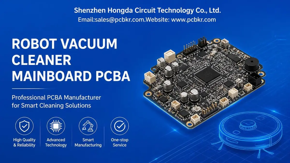
Robot Vacuum Cleaner Mainboard PCBA manufacturing requires reliable PCB fabrication, accurate component assembly, controlled sourcing, and inspection matched to the product’s electrical and mechanical requirements. Shenzhen Hongda Circuit Technology provides PCB fabrication and PCBA manufacturing services for OEM brands, ODM manufacturers, and electronics procurement teams. Send your Gerber files, BOM, and assembly requirements to sales@pcbkr.com for an engineering review and quotation.
Robot Vacuum Cleaner Mainboard PCBA Manufacturing for OEM and ODM Projects
For robot vacuum brands and contract manufacturers, the mainboard is not simply another consumer electronics PCB. It is a compact electronic assembly that connects the product’s control architecture with its power circuits, motor drives, sensors, communication interfaces, and other functional modules.
The manufacturing requirements vary considerably between product platforms. A basic robot vacuum may use a relatively straightforward control board, while a premium model with advanced navigation, multiple motor channels, wireless connectivity, and mopping functions may require more complex circuit integration.
For procurement teams, the challenge is to find a PCBA supplier that can manufacture the specified design consistently, manage component availability, and maintain production quality as orders move from engineering samples to repeat batches.
PCBKR supports customer-defined PCB fabrication and PCBA assembly requirements. The manufacturing scope can be evaluated according to the supplied design files, component specifications, production quantity, and inspection requirements.
Typical project requirements include:
- Multilayer PCB fabrication according to the approved stackup and Gerber data.
- SMT and through-hole component assembly.
- Component sourcing based on the approved BOM and purchasing requirements.
- Fine-pitch component placement and soldering according to package requirements.
- PCB electrical inspection and assembly quality inspection.
- Prototype, small-batch, and production-order manufacturing planning.
The exact production scope is confirmed during engineering review. Firmware development, navigation algorithm development, complete robot assembly, and system-level product validation should be separately specified rather than assumed to be included in a PCBA order.
What Does a Robot Vacuum Cleaner Mainboard PCBA Include?
A robot vacuum cleaner mainboard PCBA generally combines the electronic circuits required to control and coordinate different product subsystems. The actual configuration depends on the product architecture and the division of functions between the mainboard and secondary boards.
Common circuit groups include:
| Circuit group | Typical electronic content | Manufacturing considerations |
|---|---|---|
| Main control | MCU, MPU, memory and supporting circuits | IC package, placement accuracy and soldering quality |
| Motor control | Motor drivers, MOSFETs and power switching circuits | Current paths, copper capacity and thermal management |
| Power management | DC-DC converters, voltage regulators and protection circuits | Power integrity, component ratings and thermal performance |
| Battery interface | Charging control, battery connections and protection interfaces | Connector reliability and electrical requirements |
| Sensor interfaces | Interfaces for cliff, bumper, wheel and navigation sensors | Signal integrity, connector orientation and assembly accuracy |
| Wireless communication | Wi-Fi, Bluetooth and related RF components | RF layout requirements and component placement |
| Peripheral connections | Brush motors, suction fan, pumps and auxiliary modules | Harness compatibility and connector soldering |
Not every robot vacuum uses one board for all these functions. Some designs integrate most circuits on a single mainboard, while others distribute motor control, battery management, navigation, or sensor functions across separate PCB assemblies.
This distinction matters when requesting a quotation. The supplier needs to know whether the project involves only the main control board, several interconnected PCBAs, or a larger manufacturing package.
Which PCB Manufacturing Requirements Matter for Robot Vacuum Mainboards?
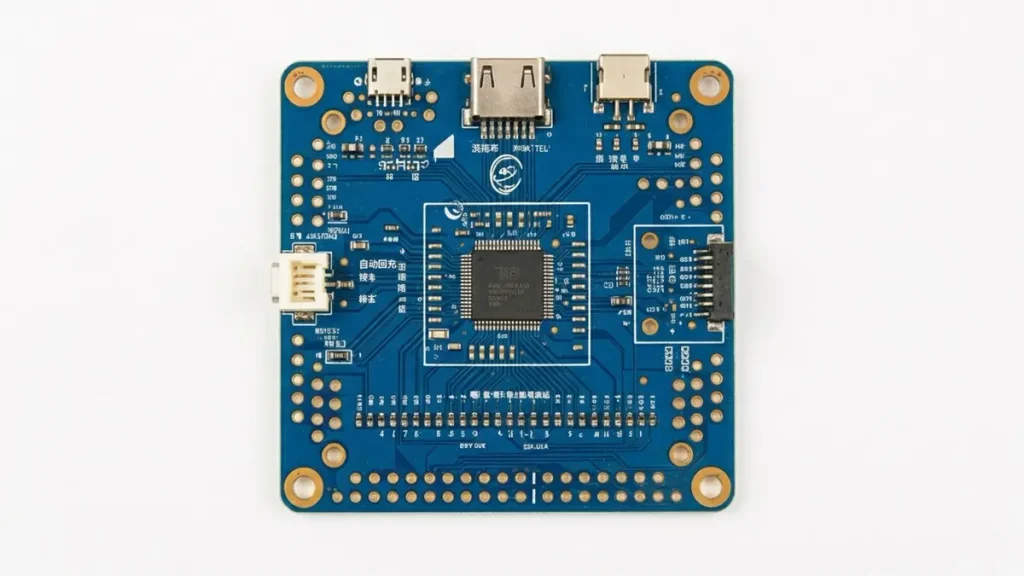
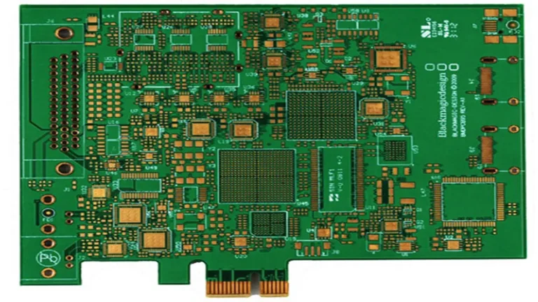
Robot Vacuum Cleaner Mainboard PCB manufacturing with multilayer FR-4 construction, copper traces and vias
The PCB specification should be determined by the actual circuit design, mechanical envelope, current requirements, component packages, and operating conditions. Selecting a multilayer or high-density PCB process without a design-based reason can increase cost without improving the finished product.
Layer Count, Board Thickness and Material Selection
Layer count depends on circuit density, routing requirements, power distribution, grounding, and the number of signals that must be connected within the available board area.
A supplier should review:
- Approved layer count and stackup.
- Base material and specified thermal properties.
- Finished board thickness and tolerance.
- Copper thickness for each layer.
- Minimum trace width and spacing.
- Minimum finished hole size.
- Surface finish and solder mask requirements.
- Board outline, slots, cutouts, and mechanical tolerances.
For compact mainboards, routing density may become a concern when MCU packages, motor drivers, power components, and multiple connectors must fit into a restricted footprint.
However, advanced HDI or microvia structures should only be selected when the design requires them. A conventional multilayer FR-4 construction may be sufficient for many robot vacuum control boards.
Current-Carrying Capacity and Thermal Management
Motor drive and power circuits require particular attention because their electrical and thermal requirements can differ significantly from low-current control circuits.
The PCB design review should consider:
- Copper thickness and current-carrying paths.
- Power and ground plane design.
- Via quantity and distribution around power components.
- Thermal paths beneath MOSFETs and power ICs.
- Component spacing and soldering accessibility.
- Connector and terminal pad construction.
A board can pass visual inspection and still experience problems if its copper distribution, thermal design, or component ratings do not match the intended operating conditions.
PCB fabrication must therefore follow the approved design data and electrical specifications rather than relying on a generic board construction.
Fine-Pitch Components and High-Density Routing
Some robot vacuum mainboards use compact processors, fine-pitch ICs, QFN packages, or BGA components. These packages require appropriate PCB pad design, solder paste control, component placement, and inspection methods.
PCBKR’s advanced fabrication capabilities include:
- SCREEN Ledia LDI imaging with an 8 µm target resolution and ±10 µm target tolerance.
- Mitsubishi UV/CO₂ laser processing with a 75 µm target feature and ±5 µm target tolerance.
- Picosecond laser processing down to 50 µm.
- mSAP fine-line capability at 8/8 µm, available since Q3 2024.
- LAUFFER vacuum lamination with process pressure settings of 80, 150, and 200 psi and vacuum below 50 mbar.
These are advanced manufacturing capabilities, not default specifications for every robot vacuum mainboard. Their relevance depends on the actual design, line-width requirements, via structure, layer registration, and production feasibility.
For standard multilayer boards, the supplier should prioritize the approved stackup, dimensional tolerances, copper requirements, and reliable production yield.
How Is Robot Vacuum Mainboard PCBA Assembly Managed?
PCBA quality depends on more than the PCB itself. Component selection, incoming inspection, solder paste printing, placement, reflow, through-hole processing, and final inspection all affect the finished assembly.
A controlled manufacturing process should address the following stages.
1. BOM Review and Component Sourcing
Before production, the BOM should be checked for complete manufacturer part numbers, package information, quantities, and approved alternatives.
Common sourcing considerations include:
- MCU and processor availability.
- Motor driver and power management IC lifecycle.
- Wireless module and sensor availability.
- Package compatibility with the PCB footprint.
- Moisture sensitivity and storage requirements.
- Approved component substitutions.
- Traceability and purchasing documentation.
A component that appears electrically similar is not necessarily a suitable replacement. Differences in package dimensions, pin assignments, electrical ratings, firmware compatibility, or RF characteristics may affect the finished product.
Any proposed substitution should be reviewed and approved by the customer before implementation.
2. SMT Assembly and Through-Hole Processing
The assembly process should match the component types and board construction.
SMT assembly commonly covers:
- Solder paste printing.
- Surface-mount component placement.
- Reflow soldering.
- Post-reflow inspection.
Through-hole processing may be required for connectors, terminals, or components specified for mechanical or electrical reasons.
Mixed-technology boards require attention to assembly sequence, component protection, soldering access, and the mechanical strength of connectors.
For BGA, QFN, and other compact packages, the assembly process must be matched to the package, PCB pad design, stencil requirements, and thermal profile.
3. Revision and Production Control
A production order should use a clearly identified revision of the PCB data, BOM, assembly drawings, and relevant test documentation.
This is particularly important when a robot vacuum product is being updated during development. Changes to the motor driver, battery interface, sensor connector, or wireless module may affect multiple assembly and inspection requirements.
Before repeat production, the manufacturer and customer should confirm:
- PCB revision and fabrication data.
- BOM revision and approved component list.
- Assembly drawing revision.
- Component substitutions and engineering changes.
- Inspection criteria and acceptance requirements.
These controls help prevent different production batches from being built against inconsistent documentation.
What Quality Inspection Is Required for Robot Vacuum Cleaner PCBA?
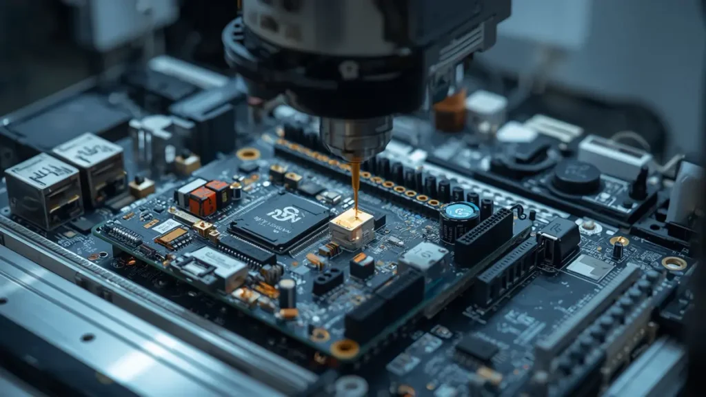
Robot Vacuum Cleaner Mainboard PCBA quality inspection using 3D AOI and X-ray testing
The inspection plan should be based on component packages, board complexity, electrical functions, and customer acceptance criteria. No single inspection method can verify every aspect of a completed PCBA.
3D AOI Inspection
Automated optical inspection helps identify visible assembly defects, including:
- Missing components.
- Incorrect component placement.
- Component polarity errors.
- Solder bridging.
- Visible soldering abnormalities.
- Misalignment and other detectable assembly defects.
3D AOI provides additional inspection information about component height and solder-joint geometry compared with conventional two-dimensional inspection.
However, AOI cannot confirm the internal quality of every solder joint or verify that a circuit performs its intended electrical function.
X-Ray Inspection for Hidden Solder Joints
X-ray inspection is useful for assemblies containing components with hidden solder connections, such as BGA packages.
Depending on the component and inspection criteria, it can help identify:
- Solder bridging beneath packages.
- Voids and solder distribution abnormalities.
- Missing or abnormal solder connections.
- Other defects that cannot be observed directly from the component surface.
The inspection criteria should be defined according to the package type, assembly requirements, and customer acceptance standards.
Electrical Inspection
Electrical inspection can help identify opens, shorts, and connectivity problems.
PCBKR supports four-wire Kelvin flying-probe testing for applicable PCB electrical requirements. The specific test coverage depends on the board design, accessible test points, and approved electrical test data.
For assembled boards, the required inspection method should be confirmed separately. Bare-board electrical testing does not replace PCBA functional testing.
Functional Testing Based on Customer Requirements
Robot vacuum mainboards may require electrical or functional verification of selected circuits, such as:
- Power input and regulated voltage outputs.
- Motor driver outputs.
- Battery and charging interfaces.
- Sensor communication interfaces.
- Connector pin assignments.
- Communication interfaces.
The test procedure must be defined against the customer’s approved test specifications, firmware, fixtures, and acceptance limits.
An important distinction for buyers: PCBA inspection and board-level functional testing are not the same as complete robot vacuum testing. Navigation accuracy, obstacle avoidance, docking performance, cleaning performance, and other product-level functions require system integration and validation. They should not be assumed to be covered by PCB assembly inspection alone.
What Manufacturing Risks Should Buyers Evaluate Before Placing an Order?
A supplier’s ability to assemble a board is only one part of the procurement decision. Buyers should also consider the risks that can affect production continuity, product consistency, and delivery schedules.
Component Lifecycle and Substitution Risk
MCUs, motor drivers, wireless ICs, and other key components may become difficult to source during a product’s lifecycle.
A supplier should identify unavailable or long-lead-time parts early and provide purchasing information for customer review.
For replacement components, buyers should confirm:
- Manufacturer and exact part number.
- Electrical and mechanical compatibility.
- Package and footprint compatibility.
- Firmware or software dependencies.
- Customer approval requirements.
Substitution should never be treated as an automatic purchasing decision.
Connector and Mechanical Assembly Reliability
Mainboard connectors often link the PCB to motors, sensors, batteries, and other modules. Their assembly quality affects both electrical connection and mechanical reliability.
Buyers should pay attention to:
- Connector orientation and placement.
- Pad and through-hole construction.
- Solder-joint quality.
- Mechanical support and mounting conditions.
- Harness compatibility.
- Assembly and handling requirements.
These details are especially important when connectors are repeatedly connected or disconnected during product assembly or servicing.
Power Circuit and Thermal Risks
Motor drivers and power management circuits can experience higher electrical and thermal stress than low-power control circuits.
The PCB layout, copper thickness, component selection, thermal paths, and soldering quality must all be consistent with the approved design.
A supplier should be able to manufacture the specified construction and follow the agreed inspection requirements. It should not independently change electrical design parameters without customer authorization.
Production Revision and Traceability Risk
Uncontrolled changes can result in boards with different components or manufacturing specifications being delivered under the same product designation.
A reliable production process should maintain clear records of the applicable PCB revision, BOM, component sourcing status, assembly instructions, and inspection results.
This is particularly important for brands that need repeat orders over an extended product lifecycle.
Can a Robot Vacuum Cleaner Mainboard PCBA Supplier Support Prototype to Mass Production?
A suitable PCBA manufacturing partner should be able to evaluate the project at different production stages and identify the requirements that change as volume increases.
| Production stage | Main buyer concern | Manufacturing focus |
|---|---|---|
| Engineering prototype | Can the supplied design be manufactured? | File review, DFM feedback and component availability |
| Small-batch production | Can the approved assembly be reproduced? | Process consistency, inspection and revision control |
| Pilot production | Is the process ready for repeat orders? | Production documentation and quality evaluation |
| Mass production | Can quality and delivery remain consistent? | Material planning, process control and batch records |
| Repeat orders | Can the original specification be maintained? | BOM control, change management and traceability |
The actual production lead time depends on PCB complexity, component availability, assembly requirements, order quantity, and testing scope.
For this reason, procurement teams should request a quotation based on the complete project documentation rather than relying on a generic lead-time promise.
PCBKR can review customer-supplied PCB and PCBA documentation to evaluate manufacturing requirements and quotation details.
For projects involving embedded control electronics beyond robot vacuum applications, see our embedded control board OEM manufacturing capabilities.
How Should You Select a Robot Vacuum Cleaner Mainboard PCBA Manufacturer?
A supplier comparison should focus on manufacturing evidence and project compatibility rather than broad claims about production capacity.
The following points can help OEM procurement teams evaluate potential suppliers.
| Evaluation area | Questions buyers should ask |
|---|---|
| PCB fabrication | Can the supplier manufacture the required layer count, material, thickness, copper and via structure? |
| SMT assembly | Can the production process support the specified component packages and assembly technology? |
| Component sourcing | Can the supplier work with the approved BOM and manage component availability? |
| Inspection | Are AOI, X-ray, electrical inspection and other required methods available for the project? |
| Functional testing | Can the supplier follow the customer’s test procedure and acceptance criteria? |
| Engineering support | Can manufacturing issues be identified and communicated before production? |
| Production control | Are PCB, BOM and assembly revisions controlled? |
| Delivery | Can material procurement and production capacity meet the required schedule? |
| Documentation | Can the supplier provide agreed inspection and production records? |
A useful supplier evaluation should include a review of the actual production files, not just a general capability presentation.
For robot vacuum projects with battery-related electronic assemblies, buyers may also review the relevant battery management system PCBA manufacturing requirements. The exact board scope and electrical responsibilities should be confirmed for each product architecture.
What Information Should You Prepare for a Robot Vacuum Mainboard PCBA Quote?
Providing complete engineering documentation helps the manufacturer evaluate the project more accurately and reduces unnecessary quotation delays.
For PCB fabrication, prepare:
- Gerber files or ODB++ data.
- NC drill files.
- PCB stackup and material requirements.
- Board thickness and copper specifications.
- Surface finish requirements.
- Controlled impedance requirements, if applicable.
- PCB quantity and target delivery date.
For PCBA manufacturing, also prepare:
- BOM with manufacturer part numbers.
- Pick-and-place or centroid file.
- Assembly drawings.
- Component polarity and special assembly notes.
- Approved component alternatives, if any.
- Test specifications and acceptance criteria.
- Programming requirements, if applicable and included in the agreed scope.
If certain documents are not yet available, provide the current design information and explain which items are still under development.
The manufacturer can then identify the information needed to complete the technical review.
Request a Robot Vacuum Cleaner Mainboard PCBA Manufacturing Quote from PCBKR
Shenzhen Hongda Circuit Technology Co., Ltd. provides PCB fabrication and PCBA manufacturing services for overseas electronics brands, OEM manufacturers, and product development teams.
For robot vacuum cleaner mainboard projects, the manufacturing review can cover:
- PCB construction and fabrication requirements.
- Multilayer and advanced PCB manufacturing feasibility.
- SMT and through-hole assembly requirements.
- Component package and sourcing considerations.
- AOI, X-ray, and applicable electrical inspection.
- Customer-defined test requirements.
- Production documentation and revision control.
Our manufacturing capabilities include advanced PCB imaging, vacuum lamination, laser processing, mSAP fine-line fabrication, 3D AOI, X-ray inspection, and four-wire Kelvin flying-probe testing. The applicable process and inspection scope will be selected according to the actual board design and customer specifications.
Send your project files to request a quotation:
Shenzhen Hongda Circuit Technology Co., Ltd.
Email: sales@pcbkr.com
Website: www.pcbkr.com
Recommended RFQ attachments: Gerber/ODB++, BOM, pick-and-place file, assembly drawing, and test requirements.
PCB fabrication and PCBA assembly for prototype, small-batch, and production projects, subject to project review.
Frequently Asked Questions About Robot Vacuum Cleaner Mainboard PCBA Manufacturing
What Information Is Required for a Robot Vacuum Cleaner Mainboard PCBA Quote?
A quotation normally requires Gerber or ODB++ files, NC drill data, a BOM with manufacturer part numbers, pick-and-place files, assembly drawings, PCB specifications, and the required inspection or testing criteria. The target quantity and delivery schedule also help the manufacturer evaluate material and production requirements.
Can a PCBA Manufacturer Provide Both PCB Fabrication and SMT Assembly?
Yes. A turnkey PCB and PCBA manufacturing arrangement can cover bare-board fabrication, component sourcing, SMT assembly, through-hole assembly where required, and agreed inspection processes. Buyers should confirm whether the quotation includes PCB fabrication, all BOM components, assembly, testing, and packaging, because service scope differs between suppliers.
Can Robot Vacuum Mainboard PCBA Be Manufactured in Small Batches Before Mass Production?
Yes, provided the PCB design, component availability, and assembly requirements are suitable for the requested quantity. Prototype and small-batch production allow buyers to evaluate manufacturing feasibility before scaling up. The production process, BOM, and PCB revision should be controlled when moving from samples to repeat orders.
How Are Robot Vacuum Cleaner Mainboard PCBAs Inspected and Tested?
Inspection may include 3D AOI for visible assembly defects, X-ray for applicable hidden solder joints, and electrical testing according to the board design. Functional testing requires an agreed test procedure, suitable fixtures, firmware where applicable, and customer-defined acceptance criteria. These checks do not automatically replace complete robot-level validation.
How Does a PCBA Manufacturer Handle Unavailable Components or BOM Substitutions?
The manufacturer should identify sourcing problems and submit proposed alternatives for engineering review. Buyers should verify the replacement’s electrical characteristics, package, footprint, pinout, and any firmware or RF dependencies. Substitutions should be documented and approved before production so that repeat orders remain consistent.
Materials and Data Sheet – Robot Vacuum Cleaner Mainboard PCBA
The following specifications provide an engineering and procurement reference for robot vacuum cleaner mainboard PCB fabrication and PCBA assembly. Final specifications, materials, and manufacturing requirements should be confirmed against the approved Gerber files, BOM, stackup, and assembly drawings.
1. PCB Materials & Construction
| Parameter | Specification |
|---|---|
| Base Material | FR-4 / High-Tg FR-4 |
| Number of Layers | 2–8 Layers |
| Board Thickness | 0.8–1.6 mm |
| Copper Thickness | 1–2 oz (35–70 μm) |
| Minimum Trace Width / Spacing | 4/4 mil (0.10/0.10 mm) |
| Minimum Finished Hole Size | 0.20 mm |
| Surface Finish | HASL / Lead-Free HASL / ENIG / OSP |
| Solder Mask | Green / Blue / Black / White |
| PCB Type | Rigid Multilayer PCB |
| Impedance Control | Available upon design requirement |
2. PCBA Assembly Specifications
| Parameter | Specification |
|---|---|
| Assembly Technology | SMT / THT / Mixed Assembly |
| Typical Component Packages | 0201 / 0402 / 0603 / QFN / BGA |
| Main Components | MCU / MPU / Motor Drivers / MOSFETs / Power ICs |
| Other Components | Sensors / Wireless Modules / Connectors / Passive Components |
| Soldering Process | Lead-Free Reflow / Wave or Selective Soldering |
| Component Sourcing | Customer-Supplied / Turnkey Sourcing |
| BOM Management | Approved BOM and Component Substitution Control |
| PCB Revision Control | Gerber, BOM and Assembly Drawing Revision Management |
3. Inspection & Testing
| Inspection Item | Available Method / Requirement |
|---|---|
| Solder Joint Inspection | 3D AOI |
| Hidden Solder Joint Inspection | X-Ray |
| PCB Electrical Testing | Flying Probe / Four-Wire Kelvin Testing, as applicable |
| Assembly Electrical Testing | According to Customer Test Specifications |
| Functional Testing | Customer-Defined Test Procedure and Acceptance Criteria |
| Quality Documentation | Inspection and Test Records as Agreed |
4. Manufacturing & Procurement Requirements
| Parameter | Requirement |
|---|---|
| Production Stages | Prototype / Small Batch / Mass Production |
| Required PCB Files | Gerber or ODB++ / NC Drill |
| Required Assembly Files | BOM / Pick-and-Place / Assembly Drawings |
| Additional Technical Documents | Stackup / Impedance Requirements / Test Specifications |
| Component Traceability | According to Customer Requirements |
| Packaging | ESD-Protective Packaging |
| Delivery Scope | Bare PCB / Assembled PCBA |
Engineering Note: The specifications above are reference options rather than guaranteed specifications for every project. Actual material grade, layer count, copper thickness, trace geometry, hole size, component packages, inspection coverage, and testing scope must be confirmed through engineering review of the customer’s design files.
For a manufacturing quotation, please send your Gerber files, BOM, and assembly requirements to sales@pcbkr.com.
About Author
David Chen LinkedIn Profile
David Chen is a Senior RF/PCB Process Engineer at Shenzhen Hongda Circuit Technology Co., Ltd., with over 12 years of experience in high-frequency PCB fabrication, impedance-controlled stack-up design, and Rogers/PTFE laminate processing. He also boasts an extensive professional background in PCBA manufacturing, PCBA testing, and PCBA optimization, with specialized expertise in high-precision PCBA fault analysis and rigorous PCBA reliability testing. The author has worked with high-layer-count server PCB fabrication, ultra-low-loss backplane stackups, and thermo-mechanical reliability optimization for AI infrastructure projects involving 112G and 224G PAM4 architectures. Skilled in complex circuit design and cutting-edge advanced PCB manufacturing processes, he delivers solutions that elevate product durability and performance across industrial applications. His technical articles focusing on PCBA manufacturing workflows and testing methodologies are widely cited by industry peers and technical platforms, and have gained attention and recognition from industry colleagues.