High Speed PCB Material Selection Guide: Megtron 6 vs Rogers vs Isola
Introduction: Why PCB Material Selection Defines High-Speed Design Success
In the era of 5G infrastructure, data center switching fabrics, and next-generation radar systems, the printed circuit board substrate is no longer an afterthought — it is a design-critical component. Engineers designing transmission lines at 10 Gbps, 56G PAM4, or 112G PAM4 speeds have long known that FR-4 simply cannot keep pace with modern signal integrity demands. The choice between Megtron 6, Rogers high-frequency laminates, Isola low-loss materials, and emerging 2026-era substrates determines whether a board meets its eye diagram mask, its insertion loss budget, and its BER targets — or fails qualification entirely.
Shenzhen Hongda Circuit Technology Co., Ltd. has processed thousands of high-speed PCB orders using these advanced laminates. This guide draws on hands-on manufacturing experience combined with current material datasheet parameters to give engineers and procurement teams a reliable, comparison-driven reference for high speed PCB material selection in 2026. For a complete overview of high-speed PCB design rules, stackup strategies, manufacturing processes, and testing methods, visit our main High Speed PCB Manufacturing guide.
Understanding Core PCB Material Parameters: Dk, Df, and Signal Integrity Fundamentals
Dielectric Constant (Dk) and Its Effect on Impedance Control
The dielectric constant, often denoted Dk or εr, measures how much a material slows the propagation of an electromagnetic wave relative to free space. In practical PCB design, Dk directly governs characteristic impedance: for a given trace geometry, a higher Dk produces a lower impedance. When Dk is tightly controlled and stable across frequency and temperature, signal propagation delay becomes predictable — a prerequisite for timing-critical differential pairs such as PCIe Gen 5/6, USB4, and 400G Ethernet lanes.
Low Dk materials allow wider traces for the same impedance target, reducing manufacturing tolerance risk and improving copper weight options. Materials like Rogers RO4003C (Dk ≈ 3.55) and Panasonic Megtron 6 (Dk ≈ 3.4–3.7) sit notably below standard FR-4 (Dk ≈ 4.2–4.5), making impedance control more achievable in tight-pitch designs.
Dissipation Factor (Df) and Its Role in Insertion Loss Budgets
Dissipation factor — also called loss tangent or tan δ — quantifies how much energy a dielectric material absorbs from the electromagnetic field passing through it. At high frequencies, even small differences in Df translate into significant dB-per-inch insertion loss differences. A laminate with Df = 0.004 will exhibit roughly double the dielectric loss compared to a material at Df = 0.002 at equivalent frequency and trace length.
For a 30-inch backplane channel running at 112G PAM4, the difference between a Df of 0.005 (standard FR-4 territory) and 0.002 (Megtron 7 / Rogers range) can exceed 8–12 dB — often the difference between a compliant channel and one requiring costly equalization upgrades.
Frequency-Dependent Behavior: 10GHz vs. 28GHz vs. 56G PAM4 Environments
Both Dk and Df are frequency-dependent. FR-4 exhibits especially erratic behavior above 5 GHz as the woven glass weave creates localized Dk variation (glass weave skew). Premium laminates maintain flatter Dk and Df curves across the 1–40 GHz range, making channel modeling more accurate and manufacturability more repeatable.
In 2026, with 224G PAM4 ecosystem development underway, material suppliers including Panasonic, Rogers (now part of DuPont), and Isola have each expanded their ultra-low-loss portfolios. Understanding material behavior across this extended frequency range is now essential for forward-looking platform designs.
Overview of Leading High-Speed PCB Material Families
Panasonic Megtron Series: Megtron 6 and Megtron 7
The Panasonic Megtron series has become the de facto reference standard for backplane and high-speed digital PCBs in the 10–112G domain. Megtron 6 offers a compelling combination of low loss, stable Dk, and processability that closely resembles standard FR-4 — a critical advantage for high-volume manufacturing.
Megtron 7 extends the performance envelope further, delivering lower Df for emerging 112G PAM4 and beyond use cases. Both materials are woven-glass reinforced, supporting multilayer constructions up to 40+ layers with conventional laser drill and through-hole processes.
Rogers High-Frequency Laminates
Rogers Corporation (now DuPont Electronics) produces ceramic-filled PTFE-based and thermoset laminates used extensively in RF, microwave, and millimeter-wave applications. RO4000 series materials, including RO4003C and RO4350B, are the workhorse products for applications from 1–77 GHz, while PTFE-based laminates like RO3003 serve mmWave radar and satellite communications bands.
Rogers materials typically feature extremely stable Dk over temperature and frequency, ultra-low Df, and tight thickness tolerances. The tradeoff is higher material cost and, in the case of PTFE laminates, more demanding fabrication processes requiring specialized drilling and surface treatment.
Isola Low-Loss PCB Laminates
Isola Group produces a broad portfolio of halogen-free, low-loss laminates positioned between mainstream FR-4 and the ultra-premium Rogers and Megtron 7 tier. Products such as Isola I-Tera MT40 and Astra MT77 have gained traction in 5G base stations, automotive radar, and data center switch cards where cost sensitivity intersects with genuine high-speed requirements.
Isola materials often provide a practical middle ground: better loss performance than FR-4 at a price point below premium Megtron or Rogers laminates, making them attractive for volume production programs where BOM cost is heavily scrutinized.
Megtron 6 vs Megtron 7: Detailed Parameter Comparison
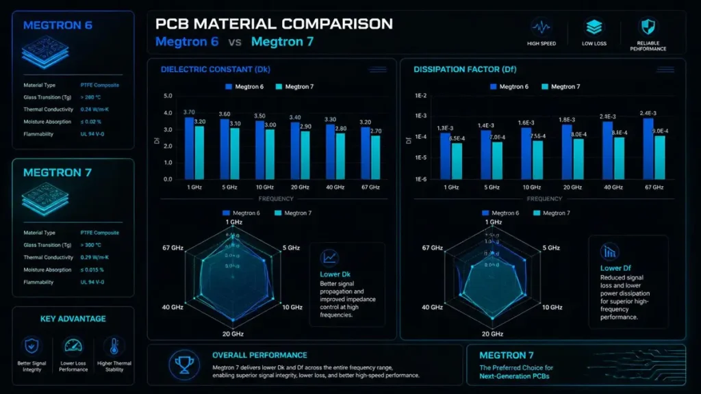
Panasonic Megtron 6 vs Megtron 7 Electrical Parameter Comparison
Megtron 6 Electrical Characteristics
Megtron 6 (Panasonic R-5775) has established itself as the industry benchmark for 25G–56G PAM4 backplane designs. Its core electrical parameters at 10 GHz are:
- Dk (at 10 GHz): approximately 3.4–3.7 (depending on resin content and construction)
- Df (at 10 GHz): approximately 0.002–0.004
- Glass transition temperature (Tg): ≥185°C (DSC method)
- CAF resistance: excellent, suitable for fine-pitch designs
These figures make Megtron 6 a reliable workhorse for server backplanes, storage interconnects, and network switches where signal integrity across long traces is paramount.
Megtron 7 Electrical Characteristics and Advantages
Megtron 7 (Panasonic R-5670) pushes the loss performance boundary further, targeting 112G PAM4 and 224G PAM4 applications:
- Dk (at 10 GHz): approximately 3.3–3.5
- Df (at 10 GHz): approximately 0.002 or below — representing a meaningful improvement over Megtron 6
- Improved surface roughness compatibility: supports low-profile copper foils (HVLP, HVLP2) for reduced conductor loss
- Thermal performance: similar Tg to Megtron 6, maintaining process compatibility
In 2025–2026, Megtron 7 has seen rapid adoption in 800G/1.6T Ethernet switch cards and next-generation AI accelerator server boards where every 0.1 dB/inch matters across 15–30 inch channels.
Megtron 6 vs Megtron 7: Application Speed Tier Guidance
| Parameter | Megtron 6 | Megtron 7 |
| Dk @ 10 GHz | 3.4 – 3.7 | 3.3 – 3.5 |
| Df @ 10 GHz | 0.002 – 0.004 | ≤ 0.002 |
| Recommended Speed Tier | 10G – 56G PAM4 | 56G PAM4 – 112G+ PAM4 |
| Typical Application | Backplane, Switch, Server | AI Accelerator, 800G/1.6T Switch |
| Manufacturing Process | FR-4-like / Standard | FR-4-like / Standard |
| Relative Cost | Moderate | Moderate-High |
Megtron 6 vs Rogers: High-Speed Digital Meets RF Performance
Rogers RO4000 Series Electrical Characteristics
Rogers RO4003C and RO4350B are the most widely used Rogers laminates for high-speed and RF applications:
- RO4003C Dk: 3.55 ± 0.05 at 10 GHz — tightly controlled
- RO4003C Df: 0.0027 at 10 GHz
- RO4350B Dk: 3.66 ± 0.05 at 10 GHz
- RO4350B Df: 0.0037 at 10 GHz
- PTFE variants (RO3003, RO3010): Df as low as 0.001 at 10 GHz, suited for mmWave
Megtron 6 vs Rogers: Dk Stability and Df Loss Comparison
The comparison between Megtron 6 and Rogers materials is frequently framed as a choice between optimized digital board processability versus RF-grade dielectric precision:
| Parameter | Megtron 6 (R-5775) | Rogers RO4003C | Rogers RO4350B |
| Dk @ 10 GHz | ~3.5 (construction-dependent) | 3.55 ± 0.05 | 3.66 ± 0.05 |
| Df @ 10 GHz | 0.002 – 0.004 | 0.0027 | 0.0037 |
| Dk Temperature Stability | Good | Excellent (< 50 ppm/°C) | Excellent |
| Process Compatibility | Standard PCB process | Modified drill / treat | Modified drill / treat |
| Cost Level | Moderate | High | High |
| Best Application Domain | Digital high-speed | RF / microwave hybrid | RF / antenna |
When to Choose Rogers Over Megtron for High-Speed PCB Designs
Rogers materials are the preferred choice when:
- The design operates above 30 GHz (mmWave radar, backhaul, 5G FR2 bands)
- Extremely tight Dk tolerance is required for antenna matching networks or filter designs
- Thermal cycling over wide temperature ranges demands near-zero Dk drift
- The board integrates both RF and high-speed digital domains requiring hybrid laminate constructions
For pure high-speed digital designs below 30 GHz, Megtron 6 typically offers better value without sacrificing channel compliance margins. Rogers is the specialist tool; Megtron 6 is the versatile workhorse.
Megtron 6 vs Isola: Balancing Performance and Cost in High-Speed PCB Fabrication
Isola Low-Loss Laminate Parameters
Isola’s high-speed portfolio covers several tiers. Key products relevant to the Megtron 6 comparison range include:
- Isola I-Tera MT40: Dk ≈ 3.45 at 10 GHz, Df ≈ 0.0031 at 10 GHz — targeting 10G–40G applications
- Isola Astra MT77: Dk ≈ 2.9–3.0 at 10 GHz, Df ≈ 0.0017 at 77 GHz — optimized for automotive radar and mmWave
- Isola Tachyon 100G: Dk ≈ 3.02 at 10 GHz, Df ≈ 0.0021 — targeting 25G–100G PAM4 digital backplanes
Megtron 6 vs Isola I-Tera MT40: Practical Comparison
| Parameter | Megtron 6 (R-5775) | Isola I-Tera MT40 | Isola Tachyon 100G |
| Dk @ 10 GHz | ~3.5 | ~3.45 | ~3.02 |
| Df @ 10 GHz | 0.002 – 0.004 | ~0.0031 | ~0.0021 |
| Halogen-Free | Yes | Yes | Yes |
| Recommended Speed | 10G – 56G PAM4 | 10G – 40G | 25G – 100G PAM4 |
| Relative Material Cost | Moderate | Lower-Moderate | Moderate |
| Global Availability | Very High | High | Moderate |
Cost-Performance Trade-offs Between Megtron 6 and Isola for Volume Production
For programs with aggressive BOM targets but genuine high-speed requirements in the 10–40G range, Isola I-Tera MT40 and comparable Isola laminates offer a credible alternative to Megtron 6. The Df performance difference is real but manageable within budget-constrained channel loss allocations.
For designs firmly in the 56G PAM4 or 112G territory, Megtron 6 (or Megtron 7 for the most demanding channels) remains the preferred choice. Isola Tachyon 100G occupies a useful niche here, offering competitive Df with potentially favorable pricing in certain regional supply chains.
Shenzhen Hongda Circuit Technology Co., Ltd. routinely processes both material families and can assist engineering teams in evaluating channel simulation data before committing to laminate selection.
Comprehensive High-Speed PCB Material Parameter Comparison Table (2026)
The following consolidated table provides a rapid-reference view of the key electrical parameters across all four material families discussed in this guide. All Dk and Df values are approximate and reflect published datasheet ranges at 10 GHz unless otherwise noted. Engineers should consult current revision datasheets from material suppliers when making final design decisions.
| Material | Series / Grade | Dk @ 10 GHz | Df @ 10 GHz | Speed Tier | Key Strength |
| Panasonic | Megtron 6 (R-5775) | 3.4 – 3.7 | 0.002 – 0.004 | 10G – 56G PAM4 | Process compatibility + low loss |
| Panasonic | Megtron 7 (R-5670) | 3.3 – 3.5 | ≤ 0.002 | 56G – 112G+ PAM4 | Ultra-low Df, AI/HPC boards |
| Rogers / DuPont | RO4003C | 3.55 ± 0.05 | 0.0027 | RF / up to 30GHz+ | Dk stability, RF precision |
| Rogers / DuPont | RO4350B | 3.66 ± 0.05 | 0.0037 | RF / microwave | Cost-effective RF alternative |
| Rogers / DuPont | RO3003 (PTFE) | 3.0 ± 0.04 | 0.001 | mmWave / >30 GHz | Lowest loss, mmWave |
| Isola | I-Tera MT40 | ~3.45 | ~0.0031 | 10G – 40G | Cost-effective low loss |
| Isola | Tachyon 100G | ~3.02 | ~0.0021 | 25G – 100G PAM4 | Mid-tier performance/cost |
| Isola | Astra MT77 | 2.9 – 3.0 | ~0.0017 @ 77GHz | 77 GHz radar / mmWave | Automotive radar optimized |
2026 PCB Manufacturing Technology Advances Affecting Material Performance
Low-Profile and Ultra-Low-Profile Copper Foils
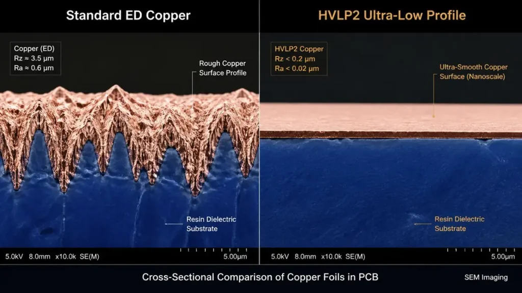
SEM Cross-Sectional Comparison: Standard ED Copper vs HVLP2 Ultra-Low Profile Foil
One of the most significant 2026-era developments in high-speed PCB fabrication is the widespread adoption of low-profile (LP) and very-low-profile (VLP) copper foils alongside HVLP (Hyper Very Low Profile) variants. Conductor loss — the ohmic loss due to the skin effect at the rough copper-dielectric interface — can equal or exceed dielectric loss in fine-line designs above 10 GHz.
When Megtron 6 or Megtron 7 laminates are paired with HVLP2 copper foils, the insertion loss improvement versus standard ED copper can reach 1–3 dB per meter at 28 GHz. Shenzhen Hongda Circuit Technology Co., Ltd. has invested in press equipment capable of achieving optimal bonding with LP/VLP copper on these advanced substrates, supporting channel designs that would otherwise require a material upgrade.
Advanced Laser Drilling and Via Fill Technology for High-Speed PCBs
Via stub resonance has long been a signal integrity challenge in thick backplane designs. In 2026, back-drilling resolution has improved to ±0.05 mm tolerance at leading manufacturers, and laser-drilled micro-via stacks (stacked and staggered configurations up to 4+N+4) allow direct routing of critical differential pairs with minimal stub length. These process advances reduce the frequency impact of parasitic capacitance, enabling Megtron 6 to serve 112G channels that would previously have mandated Megtron 7.
AI-Assisted Signal Integrity Pre-Layout Validation
Leading EDA toolchains in 2025–2026 have integrated machine-learning-assisted material property models that account for lot-to-lot Dk variation, copper surface roughness statistics, and via model extraction at the layout stage — before a prototype is built. When combined with measured material characterization data provided by fabricators like Shenzhen Hongda Circuit Technology Co., Ltd., engineers can compress qualification cycles and reduce first-spin failure risk significantly.
High-Speed PCB Material Selection by Design Scenario
10G–25G Designs: Megtron 6 or Isola I-Tera MT40
For applications operating in the 10G–25G NRZ and early PAM4 range — including 25GbE NICs, PCIe Gen 4, and CPRI fronthaul boards — both Megtron 6 and Isola I-Tera MT40 provide adequate loss performance. The decision typically rests on:
- Channel length: longer channels favor Megtron 6’s lower Df
- BOM cost targets: Isola I-Tera MT40 may offer cost savings at volume
- Supply chain: regional material availability and lead time
56G PAM4 Designs: Megtron 6 as the Primary Choice
At 56G PAM4 (28 GBaud), insertion loss budgets tighten considerably. Megtron 6 is the established industry standard at this speed tier. Engineers should also evaluate:
- Copper foil grade: HVLP copper reduces conductor loss contribution
- Layer stackup: minimizing trace length and via count in the signal path
- Back-drill strategy: eliminating stubs on thick backplane constructions
112G PAM4 Designs: Megtron 7 or Rogers Consideration
At 112G PAM4 (56 GBaud), Df becomes the dominant variable in loss budget allocation. Megtron 7 is the primary recommendation for most 112G digital backplane and chip-to-chip applications in 2026. Rogers materials become relevant when the channel includes analog/RF elements or when Dk stability over a wide temperature range is required.
- Megtron 7 + HVLP2 copper: best insertion loss for digital-dominant 112G channels
- Rogers RO4003C hybrid constructions: for mixed-signal boards with embedded RF content
- Isola Tachyon 100G: viable alternative for cost-sensitive 100G designs with shorter trace lengths
224G PAM4 and Beyond: Emerging Material Landscape in 2026
The 224G PAM4 (112 GBaud) ecosystem is actively developing in 2026, with Panasonic, Isola, and Rogers each publishing preliminary characterization data for next-generation ultra-low-loss substrates. Key trends include:
- Dk targets at or below 3.0 to reduce dielectric loss at 56 GHz+ fundamental harmonics
- Df targets approaching 0.001 or below — previously exclusive to PTFE RF laminates — in woven-glass constructions
- Novel resin systems with reduced moisture absorption to maintain stable Dk under variable humidity
- Integration of in-plane anisotropy control to reduce glass weave skew effects at mmWave frequencies
Conclusion: Matching PCB Material Properties to Your High-Speed Design Requirements
Selecting the right PCB substrate is one of the highest-leverage decisions in a high-speed electronic system design. The choice between Megtron 6, Megtron 7, Rogers, and Isola laminates is not simply a matter of cost versus performance — it is a systems-level optimization that must account for channel loss budget, frequency range, manufacturing yield, supply chain stability, and thermal environment.
To summarize the core guidance from this guide:
- Megtron 6 remains the gold-standard workhorse for 10G–56G PAM4 backplane and system-level designs, offering the best balance of processability, loss performance, and material availability.
- Megtron 7 is the preferred choice for emerging 112G PAM4 and AI infrastructure boards where every tenth of a dB counts.
- Rogers RO4000 series materials are the specialist choice for RF, microwave, and mixed-signal designs requiring ultra-stable Dk and the lowest possible Df at frequencies above 30 GHz.
- Isola laminates — particularly I-Tera MT40 and Tachyon 100G — offer compelling cost-performance trade-offs for 10G–100G designs in cost-sensitive, volume production contexts.
As a Shenzhen-based PCB manufacturer with deep experience in high-speed laminates, Shenzhen Hongda Circuit Technology Co., Ltd. works directly with engineering teams to validate material selection against real channel simulation data, recommend stackup constructions, and deliver boards with the material certification traceability that demanding customers require. Contact our engineering team to discuss your high-speed PCB material requirements.
Frequently Asked Questions: High-Speed PCB Material Selection (Procurement Edition)
What is the difference between Megtron 6 and standard FR-4, and do I need to specify it separately when ordering high-speed PCBs?
Yes — high-speed PCB laminates such as Megtron 6 must always be specified explicitly in your fabrication drawing or purchase order, as they are not interchangeable with FR-4 and carry a significant cost premium. The fundamental difference lies in dielectric loss: standard FR-4 typically exhibits a Df of 0.015–0.025 at 10 GHz, while Megtron 6 achieves 0.002–0.004. For digital interfaces above 10 Gbps, FR-4 creates excessive insertion loss that cannot be equalized out of the channel. Reputable PCB manufacturers will not substitute FR-4 for Megtron 6 without customer approval, but procurement teams should confirm this policy explicitly and request material certification documentation (UL certification card, manufacturer lot traceability) with every order.
How do I evaluate whether a PCB supplier in China can reliably process Rogers or Megtron 6 laminates?
When vetting a Chinese PCB manufacturer for high-speed laminate capability, request the following: (1) documented experience with the specific laminate family (Megtron 6, Rogers RO4003C, etc.) including reference customer projects or case studies; (2) controlled impedance test coupon data from recent production lots showing the supplier’s process capability index (Cpk) for your target impedance value; (3) evidence of calibrated TDR or VNA equipment used for impedance verification; (4) material traceability certificates linking the production lot to verified Panasonic, Rogers, or Isola material certificates of conformance; and (5) IPC-6012 Class 2 or Class 3 certification as appropriate to your application. Shenzhen Hongda Circuit Technology Co., Ltd. provides all of the above as standard practice for high-speed laminate orders.
Is Rogers laminate always better than Megtron 6 for high-frequency PCB applications?
Not necessarily — the answer depends on your frequency range, design type, and cost constraints. Rogers materials excel in RF and microwave applications above 20–30 GHz where Dk stability and ultra-low Df are non-negotiable, such as 5G mmWave antenna boards, radar systems, and satellite payload hardware. For high-speed digital applications below 30 GHz — server backplanes, switch cards, storage interconnects — Megtron 6 typically provides sufficient loss performance at lower material cost and with more straightforward PCB fabrication process compatibility. Rogers PTFE-based laminates also require specialized drilling and surface treatment processes that not all PCB manufacturers can execute correctly; selecting a fabricator with proven Rogers processing experience is essential to realizing the material’s full performance potential.
What lead times and minimum order quantities should I expect for high-speed PCB materials like Megtron 6 and Rogers?
Material availability and lead time vary by product, region, and global supply chain conditions. As of 2026, Megtron 6 (Panasonic R-5775) is broadly stocked by major PCB distributors in Asia, Europe, and North America, with typical raw material lead times of 1–3 weeks from distributor stock. Rogers RO4003C and RO4350B are similarly well-stocked, though specialty widths and thicknesses may require 3–6 weeks from the mill. Megtron 7 has seen increasing availability as demand from AI infrastructure programs has grown, with most major distributors maintaining rolling stock. Minimum order quantities for high-speed PCB fabrication vary by manufacturer: prototype quantities (5–10 panels) are available from specialized quick-turn suppliers, while volume production pricing typically applies at 50+ panels. Shenzhen Hongda Circuit Technology Co., Ltd. maintains strategic material inventory of key Megtron and Isola laminates to support both prototype and production orders with minimized lead times.
How do I compare quotes from different PCB suppliers for high-speed laminate boards to ensure I am getting equivalent material quality?
When comparing PCB quotes for high-speed laminate boards, the material specification must be matched at the product grade level — not just the brand name. Verify that each supplier’s quote specifies the exact laminate product (e.g., Panasonic R-5775 for Megtron 6, not simply ‘Megtron-equivalent’) along with the copper foil type (standard ED, LP, VLP, or HVLP), copper weight per layer, prepreg construction, and final board thickness tolerance. A lower-priced quote that substitutes a lesser-known ‘low-loss’ laminate for genuine Panasonic or Rogers material will not deliver equivalent electrical performance and may cause field failures in deployed systems. Request that each supplier provide: a stackup drawing with full material callouts, a sample material certification for the proposed laminate lot, and controlled impedance test coupon data demonstrating process capability. This level of documentation is standard practice at qualified high-speed PCB manufacturers and is the most reliable way to ensure like-for-like comparison across competing bids.
About Shenzhen Hongda Circuit Technology Co., Ltd.
Shenzhen Hongda Circuit Technology Co., Ltd. is a professional PCB manufacturer specializing in high-speed, high-frequency, and high-density printed circuit boards. With advanced manufacturing equipment and an experienced engineering team, Hongda provides reliable fabrication solutions for Megtron 6, Megtron 7, Rogers, Isola, and other advanced laminate materials. The company holds IPC-6012 Class 2 and Class 3 manufacturing certifications and serves customers in telecommunications, data center infrastructure, automotive electronics, and aerospace markets globally.
About Author
David Chen https://www.linkedin.com/in/pcbcoming
David Chen boasts an extensive professional background in PCBA manufacturing, PCBA testing, and PCBA optimization, with specialized expertise in high-precision PCBA fault analysis and rigorous PCBA reliability testing. The author has worked with high-layer-count server PCB fabrication, ultra-low-loss backplane stackups, and thermo-mechanical reliability optimization for AI infrastructure projects involving 112G and 224G PAM4 architectures. Skilled in complex circuit design and cutting-edge advanced PCB manufacturing processes, he delivers solutions that elevate product durability and performance across industrial applications. His technical articles focusing on PCBA manufacturing workflows and testing methodologies are widely cited by industry peers, research institutions, and technical platforms, solidifying his reputation as a recognized technical authority in the global circuit board manufacturing sector.