Flex PCB Materials Guide 2026: Polyimide, Copper Foil, and the Manufacturing Technology Reshaping Rigid Flex PCB Design
A flex PCB is only as reliable as the materials stacked inside it. Engineers rarely fail a design
because of copper trace width alone — they fail it by picking the wrong polyimide grade,
the wrong copper foil, or a stiffener that cannot survive a million bend cycles. At Shenzhen
Hongda Circuit Technology Co., Ltd., our engineering team fields this exact question every
week from buyers moving a rigid flex pcb project from prototype to volume: which material
stack actually holds up in the field, and which one just looks good on a datasheet?
This guide breaks down the material science behind flex pcb and rigid flex pcb
construction, then walks through the manufacturing advances shaping 2026 production —
from ultra-low-loss dielectrics to laser-based structuring — so procurement and design
teams can specify with confidence rather than guesswork.
Why Material Selection Determines Reliability in Flex PCB and Rigid Flex PCB Manufacturing
Every flexible pcb eventually moves. Whether it flexes once during assembly or bends
thousands of times inside a folding device, the base material, adhesive system, and copper
foil determine how long that circuit survives before a trace cracks or delaminates. In high
frequency boards — AI servers, radar modules, 5G small cells — the same material choices
also govern signal loss and impedance stability.
Two forces are pushing material specifications harder than they were even three years ago:
1. AI server backplanes and optical modules now demand flex sections carrying multi
gigabit signals, which rules out generic low-cost laminates.
2. Consumer devices with foldable or rollable displays put flex circuits through
continuous dynamic bending, a stress profile that static installation designs never had
to survive.
Getting the base material right is the cheapest reliability investment a design team can
make, because a failed flex circuit inside a sealed enclosure is almost never field-repairable.
What Is a Flex PCB? Core Materials Behind Flexible Printed Circuit Construction
A flex pcb is a circuit built on a bendable dielectric film rather than rigid FR4, allowing the
circuit to fold, twist, or move repeatedly without breaking. The material system behind that
flexibility has three layers: the base film, the adhesive or adhesiveless bond, and the copper
conductor.
Polyimide (PI) vs Polyester (PET): Choosing the Right Base Film
Polyimide dominates industrial and automotive flexible pcb applications because it
tolerates soldering temperatures and holds dimensional stability through repeated thermal
cycles. Polyester is cheaper and works fine in low-cost, single-use-flex consumer products,
but it cannot survive reflow soldering and degrades faster under heat. For any design that
will see a solder oven, PI is not optional — it is the only realistic choice.
Adhesiveless vs Adhesive-Based Laminates
Adhesive-based laminates bond copper to polyimide using a separate epoxy or acrylic
layer, which is lower cost but adds thickness and reduces high-frequency performance.
Adhesiveless construction bonds copper directly to the polyimide resin, producing a
thinner, more thermally stable circuit with better signal integrity — the preferred route for
any rigid-flex pcb carrying high-speed differential pairs.
Copper Foil Selection: RA Copper vs ED Copper in Flex PCB Manufacturer Practice
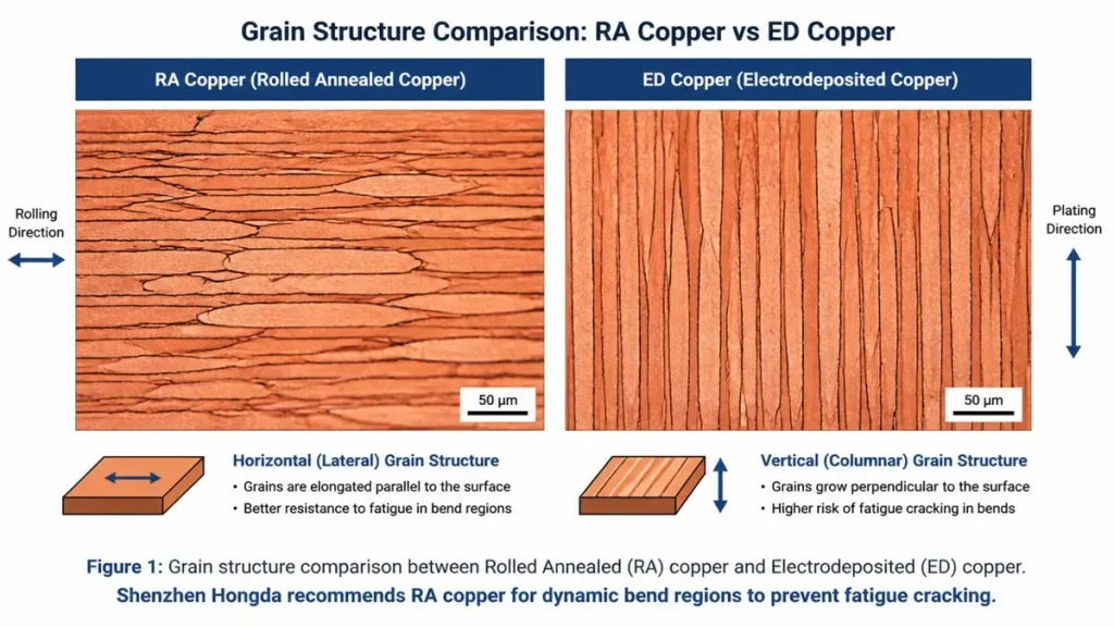
Microscopic grain structure comparison between Rolled Annealed (RA) copper and Electrodeposited (ED) copper for flex PCB manufacturing
Copper type is the single most overlooked variable in flex circuit failures. Every
experienced flex pcb manufacturer treats this as a non-negotiable spec, not a cost-down
opportunity.
Rolled Annealed (RA) copper has an elongated, layered grain structure that flexes without
work-hardening quickly, making it the standard for any dynamic bend region — hinges,
cameras, robotic joints. Electrodeposited (ED) copper has a columnar grain structure that
is cheaper to produce but cracks sooner under repeated flexing, so it belongs in static or
single-fold sections only.
Mixing the two intentionally — RA copper in the dynamic bend zone, ED copper in the
static routing zone — is a common cost-optimization move on larger boards, and a good flex
pcb manufacturer will flag this option during DFM review rather than defaulting to the
most expensive foil across the entire panel.
Coverlay vs Solder Mask: Structural Differences That Affect Bend Life
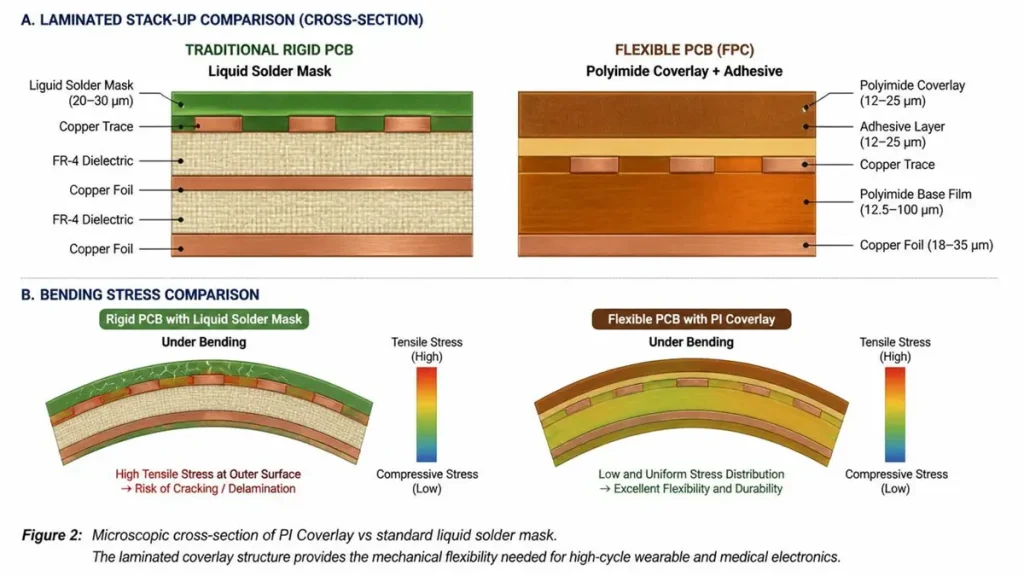
Microscopic cross-section of PI Coverlay vs standard liquid solder mask. The laminated coverlay structure provides the mechanical flexibility needed for high-cycle wearable and medical electronics.
Rigid boards use liquid solder mask because the substrate never moves. Flex circuits use
coverlay — a polyimide film laminated with adhesive over the copper — because liquid
mask cracks under repeated bending. Coverlay also seals the circuit against moisture and
mechanical abrasion far better than mask, which matters in wearable and medical-grade
flexible pcb designs exposed to sweat, cleaning fluids, or repeated handling.
What Is Rigid Flex PCB? Stiffener Design and Structural Integration
A rigid flex pcb combines rigid FR4 sections with flexible polyimide sections in a single
continuous circuit, eliminating the connectors and cables that would otherwise link
separate boards. This construction reduces assembly steps and failure points, which is why
it dominates aerospace, medical implants, and compact consumer electronics where
connector reliability is the weak link.
Stiffener Materials: FR4, Polyimide, and Aluminum
Stiffeners reinforce connector zones and component mounting areas on the flexible section
so the circuit does not flex where a rigid part is attached. FR4 stiffeners are the default for
general mechanical support and cost efficiency. Polyimide stiffeners are thinner and used
where the assembly needs partial flexibility even in the “reinforced” zone. Aluminum
stiffeners handle heat dissipation for LED and power modules where thermal spreading
matters as much as mechanical support.
Flex PCB Materials Dynamic vs Static Flex Applications: Choosing the Right Bend Strategy
This distinction changes almost every downstream material decision. A static application
— a flex section folded once during assembly and never moved again — can tolerate ED
copper, thinner PI, and simpler stiffener design. A dynamic application — a camera
module, laptop hinge, or robotic arm cable — needs RA copper, controlled bend radius
design, and fatigue-tested coverlay adhesive, because the circuit will flex tens of thousands
to millions of times over its service life. Specifying a dynamic-grade material stack for a
static application wastes money; specifying a static-grade stack for a dynamic application
causes early field failures.
How to Design Flex PCB and Rigid-Flex PCB for High-Speed and AI Server Applications
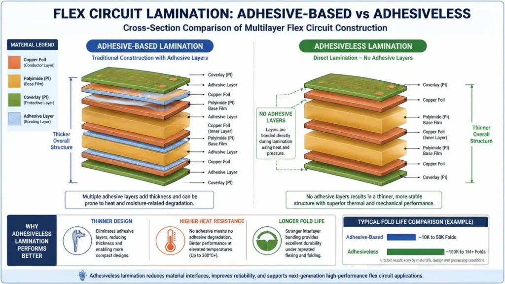
2026 Material selection matrix for high-speed AI servers and automotive applications, optimized for specific flex PCB materials constraints.
Impedance Control for High-Speed Flex in 2026
AI server and optical interconnect designs are pushing flex sections into territory once
reserved for rigid backplanes — multi-gigabit differential pairs running directly through a
bend region. Controlling impedance in a flexible pcb is harder than in rigid FR4 because
the dielectric thickness and copper roughness both shift slightly every time the circuit
bends, and any adhesive layer adds an extra dielectric variable to the stack-up math.
Designers working on these boards are increasingly specifying adhesiveless, low-loss
polyimide construction paired with smooth RA copper specifically to hold impedance
tolerance through the flex zone, not just in the static sections.
Flex PCB Materials Selection Guide: Balancing Heat, Frequency, and Cost
FPC Application Priority & Material Recommended Direction
| Priority (Application Scenario) | Recommended Direction |
|---|---|
| High temperature / automotive underhood | Polyimide base, RA copper, high-Tg adhesive or adhesiveless system |
| High-frequency / AI server, 5G | Adhesiveless PI or LCP, RA copper, tight-tolerance coverlay |
| Cost-sensitive consumer, static fold | PET or standard PI, ED copper acceptable, adhesive-based laminate |
| Dynamic, high-cycle bending | RA copper mandatory, adhesiveless PI, fatigue-rated coverlay adhesive |
Treat this table as a starting point, not a substitute for DFM review — component density,
panel size, and final enclosure design all shift the right answer.
Emerging Materials and 2026 Manufacturing Technology in Flex PCB and Rigid Flex PCB Production
Three shifts are changing what a modern flex pcb manufacturer can offer compared to five
years ago:
1. Liquid Crystal Polymer (LCP) and ultra-low-loss dielectrics are moving from niche
RF use into mainstream high-speed flex, because their dielectric loss at millimeter
wave frequencies beats standard polyimide by a meaningful margin — a direct
response to AI interconnect and 5G/6G bandwidth demands.
2. Laser direct structuring and finer laser-drilled microvias now allow flex and rigid
flex boards to reach line/space geometries that were previously rigid-board-only,
letting designers pack HDI-class routing density into flexible sections.
3. Any-layer and embedded-component techniques originally developed for rigid HDI
boards are migrating into rigid-flex construction, shrinking overall stack height in
foldable and wearable products where every fraction of a millimeter affects the
enclosure design.
A flex pcb manufacturer that has not adopted at least the finer-microvia and low-loss
dielectric side of this shift will struggle to support next-generation AI server or foldable
device programs, regardless of how competitive their pricing looks on a legacy stack-up.
How to Make Flex PCB: Inside Shenzhen Hongda Circuit Technology’s Manufacturing Process
Making a reliable flex pcb or rigid-flex pcb starts well before lamination. Shenzhen Hongda
Circuit Technology’s process runs material incoming inspection against IPC-4204 and IPC
4203 specifications for base film and adhesive systems, confirms copper foil grain type
against the dynamic/static requirement in the customer’s drawing, and runs DFM feedback
before tooling is cut — catching stiffener placement or coverlay opening issues that would
otherwise show up as bend-test failures during qualification. Panels move through
controlled lamination pressure and temperature profiles calibrated per material system,
since a profile tuned for adhesive-based laminate will under-cure or over-cure an
adhesiveless stack. Finished boards go through flex-cycle and impedance verification
appropriate to the application class before shipment.
Frequently Asked Questions: What Buyers Search Before Choosing a Flex PCB Supplier
How do I verify that a flex PCB manufacturer’s quality certifications are current?
Ask directly for the certificate numbers — ISO 9001, IATF 16949 for automotive, ISO 13485 for medical, and UL 796F for flex/rigid-flex laminate — and check the issuing body’s public database rather than relying on a PDF alone, since certificates lapse and renewal dates matter more than the logo on a webpage.
What lead time should I expect from a rigid flex PCB manufacturer in 2026?
Prototype rigid-flex typically runs 5–10 working days depending on layer count and stiffener complexity, while volume production lead time depends more on material availability — LCP and low-loss dielectrics often carry longer supplier lead times than standard polyimide, so confirm base material stock before committing to a delivery date.
Does the supplier support both small-batch prototyping and volume transition without re-qualification?
This matters more than most buyers realize: switching material
lots or copper foil suppliers between prototype and volume run can silently shift bend performance, so ask whether the manufacturer locks material sourcing across the full program or only for the initial order.
How do I compare quotes from different flex PCB and rigid-flex PCB suppliers fairly?
Line up the copper foil type (RA vs ED), base film grade, and coverlay vs solder mask spec side by side before comparing price — a lower quote using ED copper in a dynamic-bend application is not a comparable product, even if the layer count and dimensions match.
What documentation should a flex PCB manufacturer provide for a new design before
tooling starts?
Expect a DFM report addressing bend radius, stiffener placement, and
impedance stack-up (where applicable), plus a material declaration confirming base film, adhesive system, and copper type — a supplier unwilling to provide this before cutting tooling is a signal to keep looking.
Shenzhen Hongda Circuit Technology Co., Ltd. manufactures flex, rigid, and rigid-flex PCBs,
supporting material selection, DFM review, and volume production for automotive, medical,
and high-speed server applications.
About Author
David Chen https://www.linkedin.com/in/pcbcoming
David Chen boasts an extensive professional background in PCBA manufacturing, PCBA testing, and PCBA optimization, with specialized expertise in high-precision PCBA fault analysis and rigorous PCBA reliability testing. The author has worked with high-layer-count server PCB fabrication, ultra-low-loss backplane stackups, and thermo-mechanical reliability optimization for AI infrastructure projects involving 112G and 224G PAM4 architectures. Skilled in complex circuit design and cutting-edge advanced PCB manufacturing processes, he delivers solutions that elevate product durability and performance across industrial applications. His technical articles focusing on PCBA manufacturing workflows and testing methodologies are widely cited by industry peers, research institutions, and technical platforms, solidifying his reputation as a recognized technical authority in the global circuit board manufacturing sector.