Can Small PCB Milling Machines Cut Aluminum? DFM Guide to Aluminum PCB & MCPCB Depaneling
Can small pcb milling machines cut aluminumAn engineer with a desktop CNC router and a reel of aluminum-backed prototype boards. will eventually ask the same question: can the machine sitting on the bench actually cutthis material, or does the job belong somewhere else? The short answer is yes, a small mill can physically remove aluminum. The more useful answer is why that capability rarely translates into a board you’d want to ship, and where the line sits between prototyping convenience and production risk.
This guide is written for design and process engineers evaluating in-house depaneling
against outsourced fabrication, specifically for aluminum PCB (MCPCB) projects moving
from bench prototypes toward pilot builds in 2026. It reflects current design-for
manufacturability (DFM) practice rather than general machining advice, because
aluminum PCB boards fail in ways that standard FR4 boards do not.
Can Small PCB Milling Machines Cut Aluminum PCB Boards?
Yes, mechanically — a carbide end mill will bite into the aluminum substrate of an MCPCB
the same way it bites into FR4. That is not the question that matters to a production
engineer. The real question is whether the cut meets the tolerance, edge quality, and
repeatability a finished board needs, and on that point the answer is generally no for
anything beyond a one-off bench test.
Mechanical Capability vs. Manufacturing Suitability
Two separate claims get conflated in most forum discussions on this topic. “Can it cut” is a
materials-science claim about hardness and tool engagement. “Should it be used for
aluminum PCB depaneling” is a process-control claim about depth consistency across
hundreds of cuts, spindle runout, and feed-rate stability. A hobbyist router clears the first
bar easily and fails the second one almost every time, because depth-control drift of even a
few hundredths of a millimeter is the difference between a clean separation and a board
with severed copper traces.
Why Aluminum PCB Boards Behave Differently From FR4 Under the Router
Standard FR4 is a fiberglass-epoxy laminate — soft, forgiving, and largely indifferent to
modest variation in cutting parameters. An aluminum PCB board is a different structure
entirely: a solid aluminum base plate, a thin dielectric layer bonded on top, and a copper
circuit layer bonded to that. The aluminum core exists specifically to pull heat away from
LED, power, and driver components, which means the fabricator is deliberately using a
metal with much higher hardness and thermal conductivity than anything found in an FR4
stack.
That difference shows up at the tool tip immediately. Cutting resistance increases, tool wear
accelerates, and the aluminum’s tendency to smear rather than shear cleanly raises the risk
of burrs along the cut edge, localized delamination between the dielectric and the metal
core, and edge deformation that a visual inspection can miss until the board is under
thermal load in the field.
What Is an Aluminum PCB (MCPCB), Exactly?
An aluminum PCB — more precisely called a metal core PCB or MCPCB — is a circuit board
built on a metal base instead of a fiberglass one, almost always for thermal management in
LED lighting, power converters, and motor drivers. The construction is a three-layer
sandwich: copper foil for the circuit, a thermally conductive dielectric layer bonded
underneath it, and an aluminum (occasionally copper) base plate that carries heat away
from the components and into a heatsink or chassis. This is the same family of board
referred to informally as an “alu PCB” and, in UK/European sourcing documents, an
“aluminium PCB” — the terms describe the same construction, not different products.
Aluminum Box PCB and Enclosure-Integrated Designs Raise the Stakes Further
A related design variant, sometimes sourced under the term “aluminum box PCB,”
integrates the metal substrate directly into an enclosure or housing rather than treating it
as a flat board destined for a separate heatsink. These designs typically carry tighter
mechanical tolerances at the board edge because the edge itself mates with the housing.
Any burr, warp, or dimensional drift introduced during depaneling has a direct, visible
impact on fit — there’s no gasket or bracket to absorb the error the way there might be on a
standalone board.
Key Limitations of Small PCB Milling Machines When Cutting Aluminum PCB Boards
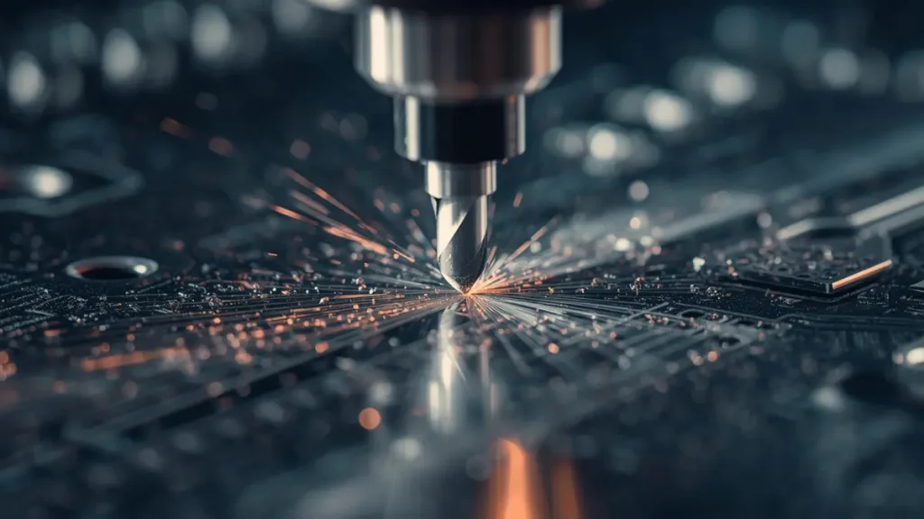
Limitations of Cutting Aluminum with Small PCB Milling Machines
Four limitations recur across desktop and benchtop equipment when the material shifts
from FR4 to metal core stock:
1. Inconsistent depth control. Small mills are not built to hold a Z-axis tolerance tight
enough to separate boards without either overcutting into active circuitry or leaving
an incomplete cut that requires manual snapping — which introduces its own stress
fractures.
2. Poor edge quality. Burr formation and rough, torn edges are common on aluminum,
and unlike FR4 dust, aluminum burrs are sharp, conductive, and difficult to deburr
without touching the circuit layer.
3. Insufficient rigidity and spindle power. Desktop machines flex under the higher
cutting forces aluminum demands, which shows up as chatter marks and dimensional
inconsistency from one board to the next.
4. No standardized process control. Without repeatable, documented depth and feed
parameters, the third board off the mill can come out meaningfully different from the
first — a problem a single prototype never reveals but a ten-unit batch always does.
DFM Risks Engineers Face When Depaneling Aluminum PCB Boards In House
The failure modes that follow from these limitations are not cosmetic; they affect whether
the board survives assembly and field use.
Electrically, an over-aggressive cut can leave micro-cracks in copper traces near the panel
edge — invisible under normal inspection but a direct path to intermittent failures once the
board is thermally cycled in the end product. Mechanically, uneven cutting force across an
aluminum core can warp or bow the board, which becomes a problem the moment it needs
to sit flush against a heatsink; a board that isn’t flat defeats the entire thermal-management
purpose of choosing an aluminum PCB in the first place. Assembly teams then inherit poor
edge tolerance that doesn’t fit jigs or enclosures designed to a tighter spec, and any
structural damage at the edge reduces the thermal path efficiency the design relied on.
Taken together, these issues show up as yield loss precisely at the moment a project is
trying to move from prototype to scale — the worst point in a schedule to discover a
depaneling problem.
Why Industrial Depth-Controlled Milling and V-Cut Are the Correct Aluminum PCB Manufacturing Process
Production fabricators solve this with equipment purpose-built for the tolerance aluminum
demands: depth-controlled CNC routing and V-scoring (V-cut), run on machines with the
rigidity and spindle accuracy a desktop unit doesn’t have.
Controlled-depth milling separates boards along a programmed path without cutting into
the surrounding circuitry, because the Z-axis is held to a tolerance the material actually
requires rather than whatever the machine happens to deliver. V-cut, where applicable to
panel geometry, scores a clean break line on both sides of the panel so boards separate
along a consistent edge with minimal burring — a meaningful advantage on aluminum,
where a rough break edge is much harder to clean up after the fact than on FR4. Industrial
equipment holds this performance across a full production panel and repeats it across every
subsequent batch, which is the actual definition of a manufacturable process rather than a
one-off successful cut.
V-Cut vs. CNC Routing for Aluminum PCB and Metal Core PCB Panels
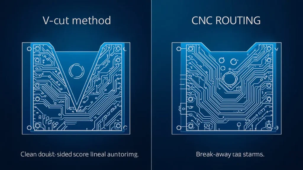
Industrial Aluminum PCB Depaneling: V-Cut vs. CNC Routing
The choice between the two isn’t arbitrary. V-cut suits simple, straight-line panel arrays
where boards can be scored and snapped along a shared edge. CNC routing with tabs
handles irregular board outlines, cutouts, and mixed panel layouts that V-cut geometry
can’t accommodate. A competent aluminum PCB manufacturer will recommend one over
the other based on panel design rather than defaulting to whichever method its shop
happens to run — and will flag a layout that isn’t well suited to either before it reaches the
cutting stage.
DFM Recommendations for Engineers Designing an Aluminum PCB Board
The decisions that prevent a depaneling problem are made at the design stage, not the
cutting stage:
1. Don’t design a panel layout around the assumption that boards will be manually
separated after fabrication — assume industrial depaneling from the outset.
2. Specify the depaneling method (V-cut or CNC routing) in the fabrication drawing
rather than leaving it to the shop’s default.
3. Lay out the panel with the chosen cutting method in mind — spacing, tab placement,
and array orientation all affect cut quality.
4. State the aluminum thickness and full layer stack-up explicitly; depth-control settings
are derived directly from this information.
Bring the PCB manufacturer into the conversation during layout, not after the Gerbers
are finalized — panel-level DFM feedback is far cheaper to act on before tooling than
after.
Soldering and Assembly Considerations After Depaneling
A clean depaneling process also protects the assembly stage that follows. Soldering an
aluminum PCB requires accounting for the base metal’s high thermal mass — heat
dissipates into the aluminum core far faster than it would through FR4, which is why reflow
profiles and hand-soldering dwell times for MCPCBs typically run longer or hotter than a
standard board would need. A board with edge damage or warp from a poor depaneling
process compounds this problem: uneven contact with the reflow carrier or heatsink
creates cold-solder-joint risk that has nothing to do with the solder paste or profile itself,
and everything to do with a cutting step that happened weeks earlier.
How Is an Aluminum PCB Made in a Production Environment?
At scale, the process runs in a defined sequence: the aluminum base is clad with dielectric
and copper foil under heat and pressure, the circuit is imaged and etched into the copper
layer, surface finish is applied, and the panel is depaneled using the depth-controlled or V
cut methods described above — with dimensional and continuity inspection at each stage.
The depaneling step is the last mechanical operation before the board reaches assembly,
which is exactly why a shortcut at that stage undoes quality control performed everywhere
earlier in the process.
When to Move From In-House Milling to a Professional Aluminum PCB Manufacturer
A handful of signals reliably mark the point where in-house cutting stops being the right
tool for the job: the design has moved to an aluminum substrate rather than FR4, the
application has real dimensional tolerances rather than “close enough for a bench test,” or
the board is heading into functional or thermal testing where a hidden micro-crack or a few
degrees of warp will show up as a false failure.
Alu PCB Prototyping vs. Production: A Cost and Risk Comparison
The economics rarely favor DIY cutting once these signals appear. A desktop-milled batch
looks cheaper on paper because it avoids a supplier’s tooling and setup cost, but that
comparison ignores the cost of a failed thermal test traced back to a warped board, or a re
spin caused by a micro-cracked trace that only shows up after the product is in a customer’s
hands. Professional sample fabrication front-loads a small, predictable cost in exchange for
removing a category of failure that otherwise surfaces late — and late failures are the ones
that cost the most schedule time.
Conclusion: Choosing an Aluminum PCB Manufacturer for 2026 Projects
Small PCB milling machines can cut aluminum in the narrow sense of the word. They are
not, and are not becoming, a substitute for depth-controlled CNC routing or V-cut on a
properly rigid, production-grade machine — the material and tolerance requirements of an
aluminum PCB board simply don’t scale down to bench equipment. The DFM decision that
matters happens at the design stage: specify the depaneling method, define the stack-up
clearly, and route the panel with production cutting in mind from the first layout revision.
Shenzhen Hongda Circuit Technology Co., Ltd. runs depth-controlled CNC routing and V
cut depaneling as standard processes across its aluminum PCB and metal core PCB
(MCPCB) production lines, supporting projects from early sample runs through volume
manufacturing. Engineers evaluating a transition from in-house prototyping to factory
samples are welcome to bring stack-up and panel layout questions to our applications team
before finalizing a board design.
Frequently Asked Questions: Sourcing an Aluminum PCB Manufacturer
How do I verify an aluminum PCB manufacturer’s quality control before placing a first order?
Ask for their incoming material certificates for the aluminum substrate and
dielectric layer, their in-process inspection points (particularly around depaneling and edge quality), and recent AOI or micro-section reports from comparable MCPCB jobs. A manufacturer confident in its process will share these without hesitation; reluctance to provide inspection data on a metal core PCB line is itself a signal worth weighing.
What lead time should I expect for an aluminum PCB board, from prototype to production quantities?
Prototype-quantity aluminum PCB boards typically run on a shorter cycle than production panels because they skip full panelization and tooling setup. Once a design moves to production volume, expect additional lead time for panel tooling, depaneling process qualification, and first-article inspection — a supplier should be able to quote both figures separately rather than one blended estimate.
What certifications or standards should a metal core PCB (aluminum PCB) supplier hold?
Look for IPC-6012 (or the relevant IPC class for your application), ISO 9001 for quality management, and UL certification if the end product is a lighting or power application subject to safety approval. For thermal-critical designs, ask specifically whether the supplier tests or reports the thermal conductivity value of the dielectric layer, since this varies by material and directly affects your thermal design margin.
How is pricing calculated for aluminum PCB boards, and what drives cost differences between quotes?
Aluminum PCB pricing is driven primarily by base metal thickness and
dielectric thermal conductivity rating, copper weight, panel utilization efficiency, MOQ, and the depaneling method specified (V-cut is generally lower-cost than CNC routing with tabs, where panel geometry allows either). Two quotes that look identical on layer count can differ significantly once these variables are itemized — ask for a line-item breakdown rather than a single number.
Can one supplier handle both small-batch aluminum PCB prototyping and later volume production?
Many aluminum PCB manufacturers run separate lines or workflows
for prototype and production quantities, so it’s worth asking directly whether the same depaneling process (V-cut or CNC routing) and quality checks apply at both stages. Consistency between prototype and production processes reduces the risk that a board qualified at sample stage behaves differently once it moves to a production panel
About Author
David Chen https://www.linkedin.com/in/pcbcoming
David Chen boasts an extensive professional background in PCBA manufacturing, PCBA testing, and PCBA optimization, with specialized expertise in high-precision PCBA fault analysis and rigorous PCBA reliability testing. The author has worked with high-layer-count server PCB fabrication, ultra-low-loss backplane stackups, and thermo-mechanical reliability optimization for AI infrastructure projects involving 112G and 224G PAM4 architectures. Skilled in complex circuit design and cutting-edge advanced PCB manufacturing processes, he delivers solutions that elevate product durability and performance across industrial applications. His technical articles focusing on PCBA manufacturing workflows and testing methodologies are widely cited by industry peers, research institutions, and technical platforms, solidifying his reputation as a recognized technical authority in the global circuit board manufacturing sector.