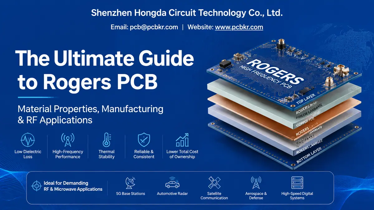
The Definitive Guide to Rogers PCB: Material Properties, Manufacturing & RF Applications
When a procurement team sources a Rogers PCB for the first time, the gap between a standard FR‑4 quote and a Rogers laminate quotation often triggers sticker shock—sometimes 3× to 5× higher per square meter. Yet seasoned RF engineers know that above 5 GHz, material choice stops being a cost decision and becomes a physics problem. Signal attenuation, impedance drift, and thermal runaway do not negotiate. This guide is written for the professional buyer who must justify material selection to engineering, negotiate with suppliers, and deliver boards that pass first‑article inspection without surprise rework.
What Is a Rogers PCB? Understanding High‑Frequency Substrate Technology
A Rogers PCB is a printed circuit board fabricated on laminate substrates manufactured by Rogers Corporation, engineered specifically for radio‑frequency (RF), microwave, and high‑speed digital applications where standard glass‑reinforced epoxy (FR‑4) fails to maintain signal integrity.
Unlike FR‑4, which uses woven fiberglass and epoxy resin, Rogers pcb material families—such as the RO4000®, RO3000®, and RT/duroid® series—employ hydrocarbon ceramics, PTFE composites, or thermoset polymer matrices. These formulations eliminate the “weave effect” that causes signal skew in high‑speed traces and deliver dielectric constants (Dk) tightly controlled to within ±0.05 across production lots.
For procurement, the critical takeaway is this: a Rogers pcb board material is not a commodity. It is a performance‑specified raw material with lot‑to‑lot electrical certificates, moisture absorption data, and thermal coefficient documentation that FR‑4 suppliers rarely provide at the same granularity.
Rogers PCB Material Properties: Dk, Df, and Thermal Performance
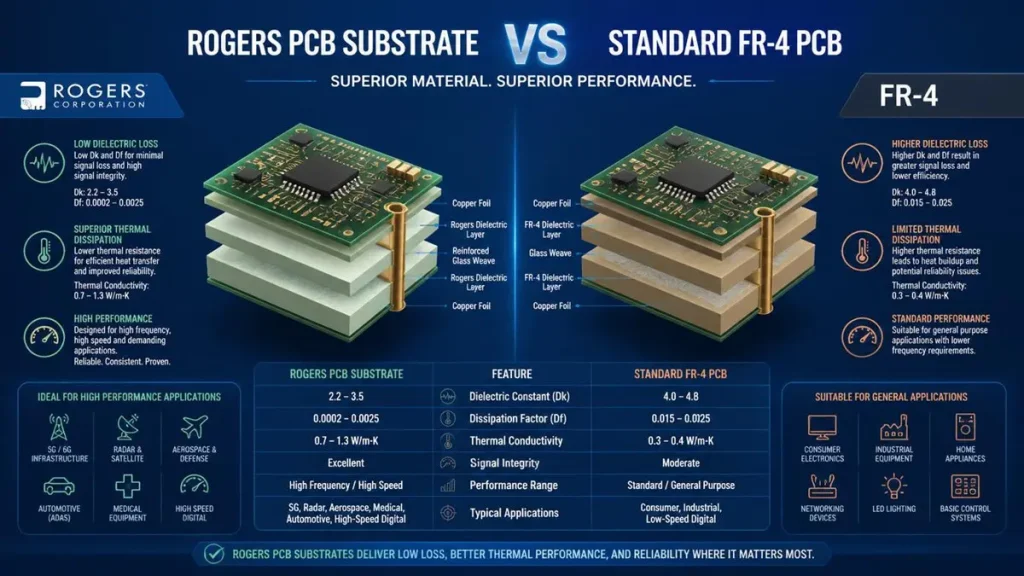
Performance and material property comparison between Rogers PCB substrate and standard FR-4 PCB
The electrical signature of any high‑frequency laminate is defined by three parameters: dielectric constant (Dk), dissipation factor (Df), and coefficient of thermal expansion (CTE). Buyers who understand these numbers can audit supplier material certificates with confidence instead of accepting vague “high‑frequency grade” claims.
Dielectric Constant (Dk) and Signal Velocity
Dk measures how much a material stores electrical energy relative to vacuum. A lower Dk means faster signal propagation and shorter wavelength in the substrate—critical for miniaturized RF circuits. Rogers pcb material typically offers Dk values between 2.2 and 3.7, compared to FR‑4’s variable 4.2–4.8 range.
Dissipation Factor (Df) and Insertion Loss
Df quantifies energy lost as heat during signal transmission. At 10 GHz, standard FR‑4 exhibits a Df of 0.018–0.025, while Rogers RO4350B registers 0.0037 and RO4003C reaches 0.0027. The RT/duroid 5880 Rogers pcb board material pushes this to an exceptional 0.0009.
This tenfold reduction in dielectric loss directly translates to longer transmission lines, fewer amplifiers, and smaller board sizes.
Thermal and Mechanical Stability
Rogers laminates maintain glass transition temperatures (Tg) exceeding 280°C and z‑axis CTE values closely matched to copper—RO4350B at 32 ppm/°C versus FR‑4’s 50–70 ppm/°C.
For multilayer boards undergoing multiple reflow cycles, this CTE match reduces plated‑through‑hole barrel cracking and delamination risk, cutting field‑failure rates by 60–70% in aerospace deployments.
| Property | Standard FR‑4 | Rogers RO4350B | Rogers RO4003C | RT/duroid 5880 |
|---|---|---|---|---|
| Dk @ 10 GHz | 4.2 – 4.8 | 3.48 ± 0.05 | 3.38 | 2.20 |
| Df @ 10 GHz | 0.018 – 0.025 | 0.0037 | 0.0027 | 0.0009 |
| Tg (°C) | ~135 | >280 | >280 | >280 |
| Z‑Axis CTE | 50–70 ppm/°C | 32 ppm/°C | 44 ppm/°C | 108 ppm/°C |
| Moisture Absorption | 0.1–0.2% | ~0.06% | ~0.06% | ~0.02% |
| Thermal Conductivity | ~0.25 W/m·K | ~0.69 W/m·K | ~0.64 W/m·K | ~0.25 W/m·K |
| Relative Cost | 1.0× (baseline) | 3–5× | 3–4× | 6×+ |
Rogers PCB vs FR4: When Premium Material Justifies the Investment
The Rogers PCB vs FR4 debate is not about which material is “better”—it is about mapping frequency requirements to total cost of ownership (TCO). FR‑4 remains the correct choice for sub‑1 GHz consumer electronics, power supplies, and basic IoT devices where signal integrity is not the limiting factor.
However, once a design crosses into 5G baseband, 77 GHz automotive radar, or Ka‑band satellite links, FR‑4’s frequency‑dependent Dk variation introduces phase distortion that no layout trick can fix. At millimeter‑wave frequencies, FR‑4’s insertion loss renders it practically unusable.
From a procurement perspective, the TCO argument favors Rogers pcb material in high‑performance systems. Reduced signal attenuation means fewer power amplifiers. Better thermal stability extends product lifespan. Lower moisture absorption eliminates environmental drift that drives warranty claims. The upfront laminate premium is often recovered within the first production year through higher yield, fewer redesigns, and reduced field service costs.
Rogers PCB Material Selection Guide: RO4000, RO3000, and RT/duroid Series
Rogers Corporation organizes its portfolio into series optimized for specific frequency bands, power levels, and fabrication methods. Buyers should match the series to the application rather than defaulting to the most expensive option.
RO4000® Series: The Gateway Rogers PCB Material
RO4003C and RO4350B are ceramic‑filled hydrocarbon laminates designed to process like FR‑4 while delivering RF‑grade performance. RO4003C offers Dk 3.38 and Df 0.0027, making it the default for cellular base station antennas, IoT modules, and 24 GHz automotive radar. RO4350B adds thermal conductivity (0.69 W/m·K) for power amplifier applications.
RO3000® Series: Ceramic‑Filled PTFE for mmWave
RO3003 (Dk 3.0, Df 0.0010) and RO3035 target 5G mmWave and phased‑array systems where phase distortion must be minimized across temperature extremes. These materials require more controlled drilling and plasma desmear cycles, so not every Rogers pcb manufacturer qualifies to produce them reliably.
RT/duroid® Series: Mission‑Critical Ultra‑Low Loss
RT/duroid 5880, with its Dk of 2.20 and Df of 0.0009, sits at the top of the performance hierarchy. It is specified for aerospace radar, missile guidance, and high‑frequency test equipment where failure is not an option. The tradeoff is specialized fabrication: PTFE‑based materials demand plasma surface activation before plating and controlled lamination pressure to prevent resin starvation.
Advanced Rogers PCB Manufacturing Processes in 2026
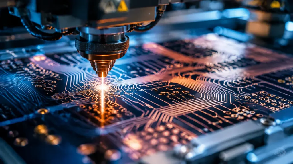
Advanced laser-drilling and high-density HDI fabrication process for Rogers high-frequency PCBs
The Rogers pcb manufacturer landscape in 2026 is defined by a single reality: demand for 5G‑Advanced, AI infrastructure, and 6G terahertz prototyping has outstripped capable capacity. Buyers who understand current process capabilities can audit suppliers against real benchmarks rather than marketing claims.
mSAP and HDI for Ultra‑Fine Rogers PCB Traces
Traditional subtractive etching struggles to hold trace geometries below 50 μm on Rogers substrates without sidewall roughness that degrades RF performance. Modified Semi‑Additive Processes (mSAP) now enable Rogers PCB fabrication down to 8 μm line and space with near‑vertical sidewalls—critical for 224G PAM4 differential pairs and 77 GHz radar feed networks.
High‑Density Interconnect (HDI) with laser‑drilled microvias eliminates via stubs that cause insertion loss notches at 56 GHz. Any‑Layer HDI stackups up to 6+N+6 configurations are now standard for AI server switch boards that route high‑speed signals through Rogers pcb board material layers.
Hybrid Rogers PCB Stackup Design and Embedded Thermal Management
Modern procurement strategies increasingly specify hybrid stackups that combine Rogers pcb material for RF layers with FR‑4 for power and mechanical support layers. This approach cuts laminate costs by 30–50% while preserving signal integrity where it matters.
For high‑power RF amplifiers and dense antenna arrays, embedded thermal management is no longer optional. Copper coin insertion, advanced thermal vias with filled silver epoxy, and direct‑bond copper (DBC) interfaces are being integrated directly into Rogers substrates to manage heat fluxes exceeding 100 W/cm².
6G‑Ready Rogers PCB Fabrication and Low‑Profile Copper Foil
As the industry pivots toward 6G and terahertz applications above 100 GHz, skin effect losses at the copper‑substrate interface dominate performance. Ultra‑smooth, low‑profile copper foils with surface roughness below 0.5 μm Rz are becoming mandatory for Rogers PCB designs in next‑generation wearable RF, satellite transponders, and automotive 4D imaging radar.
Rogers PCB Applications Across Industries

Key high-frequency applications powered by Rogers PCB materials in telecommunications, automotive, aerospace, and AI sectors
5G and 6G Telecommunications Rogers PCB
Base station active antenna units (AAU) and massive MIMO arrays rely on Rogers pcb material for beamforming networks at 28 GHz and 39 GHz. The stable Dk across temperature ensures phase coherence across hundreds of radiating elements—any drift destroys beam steering accuracy.
Automotive Radar and ADAS Rogers PCB Solutions
77 GHz long‑range radar and 79 GHz short‑range sensors for autonomous driving require RO3003 or RO4835 laminates. These materials survive under‑hood thermal cycling (-40°C to +150°C) while maintaining the tight impedance tolerance needed for FMCW chirp integrity.
Aerospace and Satellite Communication Rogers PCB
Satellite payloads and phased‑array terminals specify RT/duroid 5880 for Ka‑band (26.5–40 GHz) and Q‑band (33–50 GHz) operation. The material’s near‑zero moisture absorption prevents performance drift in vacuum environments where outgassing and humidity cycling are non‑issues, but launch vibration and thermal shock are severe.
AI Server and High‑Speed Data Center Rogers PCB
While AI server backplanes often use Megtron 6/7 for 112G/224G digital signaling, Rogers PCB layers are increasingly integrated into hybrid stackups for clock distribution and RF front‑ends within the same chassis. This convergence of digital and RF on a single board demands suppliers capable of both disciplines.
How to Choose a Rogers PCB Manufacturer: Procurement Decision Framework
Selecting a Rogers pcb manufacturer requires evaluating capabilities that go far beyond standard PCB fabrication. The following framework helps procurement teams move beyond unit‑price comparisons to total‑cost‑of‑ownership assessments.
Certifications and Quality Systems for Rogers PCB Suppliers
Verify that the supplier holds ISO 9001, AS9100D (for aerospace), IATF 16949 (for automotive), and IPC‑6012 Class 3/3A certification. For medical applications, ISO 13485 is non‑negotiable. These certifications indicate process maturity, but the buyer should also request material traceability documentation (AS9102) and lot‑specific Dk/Df test reports from the laminate manufacturer.
Equipment Capability and Process Control
A qualified Rogers pcb manufacturer must operate equipment capable of handling Rogers‑specific processing requirements:
‑ Laser Direct Imaging (LDI): SCREEN Ledia or Orbotech systems for ±5% impedance control on fine‑line RF traces
‑ Laser Drilling: Mitsubishi UV/CO₂ hybrid systems for 50 μm microvias in Any‑Layer HDI configurations
‑ Lamination: LAUFFER or equivalent presses with programmable temperature/pressure profiles for hybrid Rogers‑FR‑4 stackups
‑ Metrology: Nordson DAGE X‑Ray for void detection, TDR for impedance verification, and network analyzers for insertion loss validation up to 40+ GHz
DFM Engagement and Prototyping Speed
Rogers material is too expensive for trial‑and‑error prototyping. A competent supplier provides complimentary DFM reviews with 24‑hour turnaround, identifying impedance discontinuities, thermal hotspots, and hybrid stackup delamination risks before the first panel is cut. No‑MOQ prototype support with 5–7 day lead times for 4‑layer boards and 10–14 days for high‑layer‑count RF backplanes separates strategic partners from commodity vendors.
Rogers PCB Cost Analysis and Total Cost of Ownership
The headline price of a Rogers PCB prototype can range from $200 to $800 per square meter depending on layer count, material series, and surface finish—compared to $30–$60 for equivalent FR‑4. However, procurement teams should model the following TCO factors:
| Cost Driver | FR‑4 Impact | Rogers PCB Impact |
|---|---|---|
| Signal loss compensation | Extra amplifiers, larger boards | Minimal—design stays compact |
| Thermal management | Heatsinks, fans, reliability failures | Embedded copper coins, lower CTE |
| Environmental drift | Calibration cycles, warranty returns | Stable Dk/Df across humidity |
| Yield loss | Higher scrap at RF frequencies | Predictable fabrication on qualified lines |
| Redesign cycles | Multiple spins for impedance | First‑pass success with proper DFM |
For programs shipping 10,000+ units annually, the Rogers laminate premium is typically recovered within two production quarters through reduced BOM cost and higher field reliability.
Why Shenzhen Hongda Circuit Technology Is Your Strategic Rogers PCB Partner
Shenzhen Hongda Circuit Technology Co., Ltd. (PCBKR) operates as a specialist Rogers pcb manufacturer with capabilities that bridge the gap between tier‑1 factory overhead and boutique supplier responsiveness.
Full‑Spectrum Rogers PCB Material Qualification
Our approved vendor list includes the complete Rogers Corporation portfolio—from process‑friendly RO4003C and RO4350B for cost‑optimized RF modules, to RT/duroid 5880 for aerospace and defense programs. We maintain lot‑specific material certificates with Dk/Df traceability and full AS9102 documentation for mission‑critical deliveries.
2026‑Leading Manufacturing Infrastructure
Our Shenzhen facility deploys equipment specifically qualified for Rogers pcb board material processing:
‑ SCREEN Ledia LDI exposure for 8 μm/8 μm mSAP fine‑line geometries
‑ Mitsubishi UV/CO₂ laser drilling for 50 μm microvias in Any‑Layer HDI
‑ LAUFFER lamination systems with hybrid stackup recipe management
‑ Nordson DAGE X‑Ray and 3D AOI for 100% defect coverage
‑ Network analyzer testing to 40 GHz for insertion loss and return loss validation
6G‑Oriented RF Technology Center
Hongda Circuit has established a 2026 high‑frequency PCB technology research center oriented to the forward layout of 6G terahertz technology. The center holds core patents in AI dynamic compensation technology, ultra‑precise process control, and integrated thermal management. We maintain long‑term cooperative relationships with the IPC International Electronic Industry Connection Association and leading substrate manufacturers worldwide, ensuring our Rogers PCB processes remain at the industry frontier.
Procurement‑Aligned Service Model
We understand that procurement teams need more than technical capability—they need predictability:
‑ No‑MOQ prototypes with 30‑minute inquiry response and 1‑hour engineering evaluation
‑ 24‑hour DFM feedback with stackup optimization and impedance simulation
‑ Locked process parameters via automated recipe management—no batch‑to‑batch variation
‑ 36‑month after‑sales warranty on automotive and aerospace‑grade Rogers PCB products
‑ Full‑process digital traceability from material receipt through final test
Whether you need 5 pieces for medical device validation or 50,000 pieces for 5G infrastructure mass production, our engineering team treats every Rogers PCB program with equal technical rigor.
Ready to source your next Rogers PCB project? Submit your Gerber files, stackup requirements, and material specifications to sales@pcbkr.com for a complimentary DFM review, impedance simulation, and competitive quotation within 30 minutes.
Rogers PCB Procurement FAQ: What Buyers Ask Before Placing an Order
How do I verify that a Rogers PCB manufacturer uses genuine Rogers laminate and not counterfeit material?
Request the supplier’s material certificate of conformance (C of C) with the Rogers Corporation lot number. Cross‑reference this with Rogers’ online verification portal or demand third‑party XRF analysis of the substrate. At Shenzhen Hongda Circuit Technology, we provide full lot traceability from raw material receipt through finished board shipment, including AS9102 documentation for aerospace programs.
What is the typical lead time for Rogers PCB prototypes versus mass production?
Standard 4‑layer Rogers PCB prototypes with RO4350B material ship in 5–7 days. High‑layer‑count RF backplanes (12+ layers) with selective hard gold or hybrid stackups require 10–14 days for first articles. Mass production lead times scale with layer count and testing requirements—typically 3–4 weeks for volumes above 1,000 panels. Our No‑MOQ policy means you can validate with 5 pieces before committing to volume.
Can Rogers PCB be fabricated in hybrid stackups with FR‑4 to reduce cost?
Yes. Hybrid Rogers pcb board material stackups—where RF signal layers use Rogers RO4350B or RO4003C and power/mechanical layers use FR‑4—are now standard practice. This configuration can reduce laminate costs by 30–50% while preserving signal integrity on critical traces. The key is selecting a Rogers pcb manufacturer with lamination presses qualified for dissimilar CTE materials and documented hybrid stackup recipes.
What Dk/Df tolerance should I specify in my Rogers PCB procurement contract?
Specify Dk tolerance of ±0.05 and Df within ±0.0005 of the datasheet value at your operating frequency. For designs above 20 GHz, demand lot‑specific test data from the laminate manufacturer rather than generic datasheet values. Impedance control should be specified at ±5% or tighter for 50 Ω RF traces, with TDR validation reports included in the first‑article inspection package.
How does Rogers PCB total cost of ownership compare to FR‑4 over a 5‑year product lifecycle?
While Rogers PCB unit cost is 3–5× higher than FR‑4, the TCO often favors Rogers within 12–18 months for high‑frequency products. The calculation includes: eliminated signal amplification stages (BOM reduction), smaller board form factors (enclosure savings), fewer thermal management components, reduced field failure rates (warranty cost avoidance), and zero redesign cycles due to first‑pass impedance success. For automotive radar and telecom infrastructure programs, Rogers is typically the lower‑TCO choice despite the higher upfront laminate price.
Conclusion
The Rogers PCB is not merely an upgraded substrate—it is a strategic engineering decision that determines whether a high‑frequency product meets its performance specification or fails in the field. For procurement professionals, the task is to translate technical requirements into supplier qualification criteria: genuine material traceability, equipment capable of mSAP and hybrid lamination, and a quality system audited to IPC Class 3 or AS9100D standards.
As 5G evolves into 5G‑Advanced and 6G terahertz research accelerates, the demand for precision Rogers pcb material fabrication will only intensify. Buyers who partner with Rogers pcb manufacturers investing in 2026 process technology—LDI imaging, laser microvia drilling, and AI‑enhanced inspection—will secure supply chain resilience while their competitors struggle with yield loss and redesign delays.
Shenzhen Hongda Circuit Technology Co., Ltd. (www.pcbkr.com) combines advanced Rogers PCB manufacturing capability with the procurement agility that tier‑1 factories cannot match. From RO4003C IoT prototypes to RT/duroid 5880 satellite payloads, our engineering team delivers zero‑defect reliability without the premium overhead.
Contact us today:
📧 Email: sales@pcbkr.com
📞 Phone: +86 0755 23720053
🌐 Website: www.pcbkr.com
📍 Address: Room 1608‑1610, Research Development Comprehensive Building, Baoyunda Logistics Center, Baoan, Shenzhen, China
About Author
David Chen https://www.linkedin.com/in/pcbcoming
David Chen boasts an extensive professional background in PCBA manufacturing, PCBA testing, and PCBA optimization, with specialized expertise in high-precision PCBA fault analysis and rigorous PCBA reliability testing. The author has worked with high-layer-count server PCB fabrication, ultra-low-loss backplane stackups, and thermo-mechanical reliability optimization for AI infrastructure projects involving 112G and 224G PAM4 architectures. Skilled in complex circuit design and cutting-edge advanced PCB manufacturing processes, he delivers solutions that elevate product durability and performance across industrial applications. His technical articles focusing on PCBA manufacturing workflows and testing methodologies are widely cited by industry peers, research institutions, and technical platforms, solidifying his reputation as a recognized technical authority in the global circuit board manufacturing sector.