Why High-Tg FR4 PCBs Are Essential for Automotive and Electric Vehicle (EV) Electronics
The automotive electronics supply chain is undergoing its most aggressive qualification cycle in decades. If you are a procurement manager, hardware engineer, or Tier 1 supplier sourcing automotive-grade PCBs, you have likely already encountered the same painful pattern: a board that passes initial electrical validation fails six months later after thermal cycling, vibration, or lead-free reflow. The root cause is almost always the same—standard FR-4 laminate was specified where High-Tg FR4 PCB material was required.
At Shenzhen Hongda Circuit Technology Co., Ltd. (www.pcbkr.com), we manufacture IATF 16949 certified High-Tg PCB solutions specifically engineered for under-the-hood and EV powertrain environments. This guide is structured around the actual decisions you must make during supplier qualification—from material selection and subsystem mapping to certification auditing and long-term supply agreements.
Understanding High-Tg FR4 Material: The Foundation of Automotive PCB Reliability
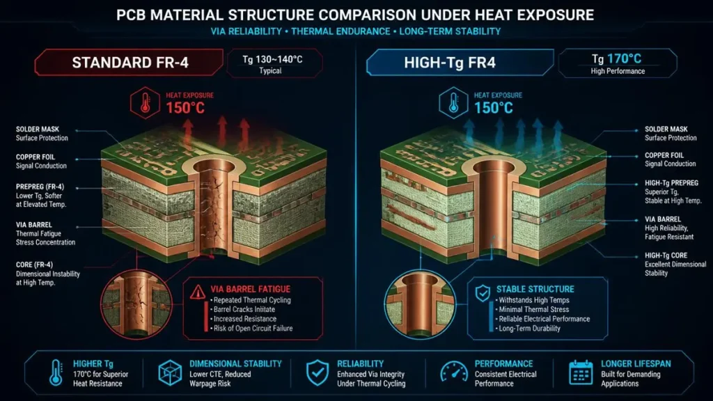
Standard FR-4 vs High-Tg FR4 Thermal Structure & Via Reliability Comparison
Before evaluating suppliers, procurement teams need a clear material baseline. High glass transition temperature PCB substrates are defined by IPC-4101 /26 and /126 slash sheets as laminates with a Tg of 170°C or higher. Standard FR-4 (Tg 130–140°C) begins to soften during lead-free reflow peaks of 240–260°C, risking pad cratering, z-axis expansion, and via barrel cracks.
Why Tg 170°C Is the Minimum Threshold for Automotive Electronics
A practical rule used by automotive OEMs is that continuous operating temperature should sit at least 20–25°C below the material’s Tg. Under-the-hood ECUs and EV battery compartments routinely see ambient temperatures exceeding 125°C. A High-Tg FR4 PCB with Tg ≥170°C maintains structural rigidity and dielectric stability where standard materials would transition into a rubbery state.
Common automotive-grade High-Tg laminates include:
- Shengyi S1000-2 (Tg 170°C) – proven in BMS and inverter applications
- Isola IS410 (Tg 180°C) – preferred for multilayer automotive controllers
- IT-180A (Tg ≥175°C) – optimized for high-layer-count, lead-free assembly
Procurement checkpoint: Ask your candidate supplier for the exact laminate grade and IPC-4101 slash sheet. A fabricator who answers “High-Tg FR-4” without specifying the resin system and Tg value has not passed the first filter.
Thermal Challenges in Modern Automotive Environments
Automotive electronics no longer live in climate-controlled cabins. Modern EV architectures concentrate power electronics under the hood and beneath the chassis, creating thermal envelopes that consumer-grade PCBs cannot survive.
Under-the-Hood Temperature Extremes and Thermal Cycling
Internal combustion engine compartments and EV motor bays expose PCBs to rapid temperature swings from −40°C cold-start to +150°C sustained operation. Standard FR-4’s higher coefficient of thermal expansion (CTE) in the z-axis causes plated through-hole fatigue after repeated cycling. High-Tg automotive PCB materials reduce CTE and extend mean time between failures (MTBF) by maintaining mechanical integrity across thousands of thermal shock cycles.
Lead-Free Reflow and Solder Joint Integrity
RoHS compliance mandates lead-free solder alloys with reflow profiles peaking at 245–260°C. During assembly, the PCB substrate itself experiences thermal stress that can weaken the bond between copper foil and epoxy resin. Lead-free compatible PCB material with elevated Tg minimizes resin softening, reducing the risk of pad lifting and interconnect degradation during both initial assembly and field rework.
Key Automotive Subsystems Relying on High-Tg FR4
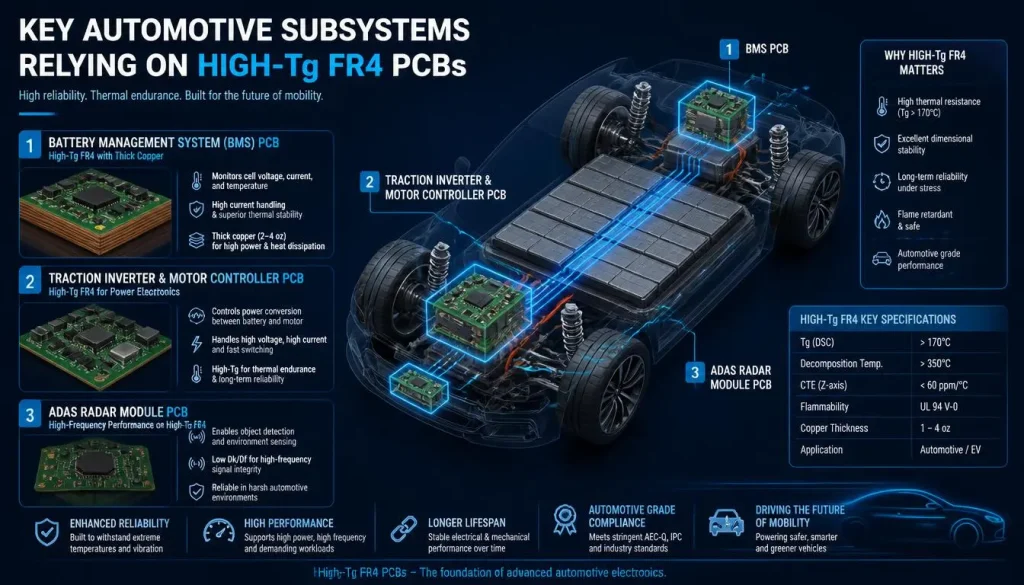
Key Automotive Subsystems Relying on High-Tg FR4 PCBs
Not every automotive PCB requires High-Tg material, but the following subsystems are non-negotiable use cases. When you map your BOM against these applications, you can prioritize which boards warrant the material upgrade.
Battery Management System PCB (BMS) for EV Platforms
The EV battery management system PCB is the most thermally stressed control board in the vehicle. Positioned inside or adjacent to the battery pack, BMS boards monitor hundreds of cells while managing balancing currents and high-voltage isolation. Power MOSFETs, balancing resistors, and shunt current sensors generate localized heat that standard FR-4 cannot dissipate reliably.
Design requirements we see from EV OEMs:
- Heavy copper PCB (2–4 oz) for current-carrying traces
- Thermal via arrays to spread heat from power devices
- High CTI (Comparative Tracking Index) laminates for 400V–800V isolation
- Halogen-free High-Tg FR4 for environmental compliance
At Shenzhen Hongda Circuit, our BMS PCB production line combines sequential lamination HDI technology with thick-copper plating to achieve both dense routing and high current capacity in the same stackup.
Inverter and Motor Controller PCB Thermal Management
EV traction inverters convert DC battery power to three-phase AC for the drive motor. IGBT and SiC MOSFET modules switch at high frequencies, generating substantial heat in the gate-driver and power-stage sections. EV inverter PCB thermal management demands not only High-Tg cores but also metal-core or hybrid FR4-aluminum constructions for direct heat sinking.
Our manufacturing floor addresses this with:
- Laser direct imaging (LDI) for ±8 μm trace alignment accuracy on dense gate-driver layers
- Automated X-ray inspection for void detection in thermal vias and heavy-copper plated holes
- Controlled impedance routing to maintain signal integrity between MCU and isolated gate drivers
ADAS and Radar Sensing Module PCBs
Advanced driver-assistance systems (ADAS) integrate radar, LiDAR, and camera modules that must function flawlessly across desert heat and arctic cold. High-Tg multilayer PCB for ADAS modules typically requires 6–12 layers with mixed-signal routing, controlled impedance, and strict flatness tolerances for mmWave antenna integration.
The combination of High-Tg FR4 laminate with low-Dk prepregs enables stable dielectric constant across temperature, which is critical for RF performance consistency in 77 GHz radar applications.
Quality Standards Required: IATF 16949, IPC-6012DA, and IPC Class 3
Procurement teams in automotive cannot treat PCB sourcing as a higher-volume version of consumer electronics purchasing. The certification stack is categorically different, and missing any layer exposes your program to field-failure liability.
IATF 16949 Certification at the Production Site
IATF 16949:2016 is the baseline quality management system for automotive suppliers. It is built on ISO 9001 but adds core tools including APQP, PPAP, FMEA, SPC, and MSA.
Critical procurement verification: Confirm the certificate is current, covers the manufacturing plant (not just a sales office), and was issued by an accredited certification body such as TÜV, SGS, or Bureau Veritas. Many buyers discover too late that their supplier’s IATF certificate applies only to headquarters.
Shenzhen Hongda Circuit maintains IATF 16949 certification at our Shenzhen production facility, with full APQP documentation support for new product introduction.
IPC-6012DA Automotive Addendum and IPC Class 3
While IPC-6012 is the generic qualification specification for rigid PCBs, IPC-6012DA is the automotive addendum that tightens tolerances on:
- Conductor width and spacing accuracy
- Plating thickness consistency (copper, nickel, gold)
- Solder mask adhesion and coverage
- Solderability and cleanliness requirements
IPC Class 3 (High-Reliability / Life Support) adds further constraints on annular ring integrity, dielectric thickness uniformity, and electrical test coverage. Any automotive PCB with IPC-6012DA compliance must be manufactured with process controls that go far beyond commercial-grade Class 2 boards.
Reliability Testing That Separates Automotive-Grade from Industrial-Grade
Request these test reports during supplier qualification:
- Thermal shock testing: −40°C to +125°C, 1,000 cycles minimum
- HAST (Highly Accelerated Stress Test): 130°C / 85% RH, 96 hours
- CAF (Conductive Anodic Filament) resistance: Critical for high-voltage BMS boards
- Vibration and mechanical shock: Per IEC 60068-2-6 and -27
A supplier who cannot produce dated test data for a comparable board construction is not an automotive PCB manufacturer—they are a commercial fabricator hoping to win automotive business.
Advanced Manufacturing Capabilities for Automotive High-Tg PCB Production

Precision UV Laser Direct Imaging (LDI) Exposure Process for Automotive PCBs
Material selection and certifications mean nothing if the factory floor cannot hold the tolerances. When you audit a long-term reliable automotive PCB supplier, evaluate the equipment list and process control systems with the same rigor you apply to material specs.
Laser Direct Imaging (LDI) and Precision Etching for Fine-Line Automotive Designs
Modern automotive ECUs and ADAS modules require trace-and-space geometries below 75 μm on outer layers. Traditional contact exposure introduces alignment errors that compound across multilayer lamination cycles. Our facility deploys LDI exposure systems that eliminate phototool distortion, achieving ±5 μm registration accuracy on 6–16 layer High-Tg multilayer PCBs.
HDI and Sequential Lamination for Space-Constrained EV Electronics
EV domain controllers and BMS slave boards pack increasing functionality into shrinking enclosures. HDI PCB manufacturing with laser-drilled microvias (typically 0.10–0.15 mm diameter) enables routing beneath fine-pitch BGAs and QFN packages. We support 1+N+1, 2+N+2, and any-layer HDI stackups using High-Tg cores and matching prepregs to prevent delamination during sequential lamination thermal cycles.
AI-Enhanced AOI and Full Traceability via MES
Automotive production demands defect detection rates exceeding 99.9%. Our lines integrate AI-driven automated optical inspection (AOI) and 3D solder paste inspection (SPI) to catch bridging, insufficient solder, and component placement drift before boards reach electrical test.
Equally important for procurement: our Manufacturing Execution System (MES) provides lot-level traceability from raw laminate reel to finished board shipment. In the event of a field issue, we can isolate suspect lots within hours—a capability that is not optional when you are supporting a 15-year vehicle service life.
Partnering with an Experienced Automotive PCB Manufacturer
The final stage of the procurement decision chain is not price negotiation—it is risk mitigation. A High-Tg FR4 PCB supplier for automotive applications must offer operational commitments that match the product lifecycle.
Lot-Level Traceability and Process Change Notification (PCN)
Automotive recalls are costly and brand-damaging. Your PCB supplier must maintain:
- Lot-level traceability: Linking each board to raw material lots, process parameters, and inspection records
- Formal PCN process: 90–180 days advance notice for any material, process, or supplier change
- EOL management: 24–36 month advance notification before any laminate or surface finish chemistry reaches end-of-life
At Shenzhen Hongda Circuit, these are contractual commitments, not verbal assurances.
From Prototype to Mass Production Without Re-qualification
A common procurement pain point is the gap between prototype fabrication and mass production. A board that works at 5 pieces from a quick-turn shop may yield poorly at 5,000 pieces from a volume factory. We bridge this gap by running prototypes on the same IATF 16949-qualified lines, using the same approved materials and processes, that will later handle your production volumes. This eliminates re-qualification cycles and reduces time-to-market by weeks.
Engineering Engagement Before Fabrication
The most expensive PCB problem is one discovered after the first article. Our engineering team reviews Gerber data, stackup designs, and DFM constraints before order confirmation, flagging potential yield issues such as insufficient annular ring, via aspect ratio risks, or impedance discontinuities. For automotive buyers, this early engagement is often the difference between a smooth PPAP approval and a costly redesign.
Frequently Asked Questions (FAQ) — Automotive PCB Procurement
What certifications should I verify before placing an automotive PCB order?
Verify IATF 16949:2016 at the production site (not headquarters), IPC-6012DA familiarity with documented inspection records, and IPC Class 3 manufacturing capability. Additionally, request reliability test data covering thermal shock (−40°C to +125°C), HAST, and CAF resistance for a comparable board construction. ISO 9001 alone is insufficient for automotive supply.
How do I know if my automotive design needs High-Tg FR4 instead of standard FR-4?
If your board operates above 110°C continuously, undergoes lead-free reflow assembly, carries 6+ layers with dense vias, or is installed in an under-the-hood or EV battery environment, High-Tg FR4 (Tg ≥170°C) is required. Standard FR-4 (Tg 130–140°C) risks pad cratering, z-axis expansion, and via failure under these conditions.
What is the difference between IPC Class 2 and Class 3 for automotive PCBs?
IPC Class 2 (Dedicated Service) allows minor cosmetic imperfections and reduced annular ring requirements. IPC Class 3 (High-Reliability) demands stricter tolerances, tighter conductor spacing control, and 100% electrical test coverage. For safety-critical automotive subsystems—BMS, braking control, ADAS—Class 3 is the non-negotiable standard.
How can I ensure my PCB supplier can support a 15-year automotive product lifecycle?
Demand contractual commitments for lot-level traceability, a formal Process Change Notification (PCN) procedure with 90–180 day advance notice, and 24–36 month EOL notification with last-time-buy provisions. Audit their MES or ERP system to confirm traceability is operational, not theoretical.
What advanced manufacturing capabilities should an automotive PCB partner have in 2026?
Look for LDI exposure for fine-line accuracy, HDI laser drilling for dense routing, AI-enhanced AOI/X-ray inspection for defect detection above 99.9%, thick copper plating (2–4 oz) for power electronics, and MES-based lot traceability. These capabilities directly correlate with yield consistency and long-term reliability in automotive environments.
Make Material Science Your First Line of Defense
In automotive and EV electronics, PCB failure is rarely a soldering defect—it is usually a material failure that manifests months or years after deployment. Specifying High-Tg FR4 PCB material is not a cost increase; it is insurance against warranty claims, recalls, and supplier churn.
If you are evaluating IATF 16949 certified High-Tg PCB manufacturers for your next automotive program, start with material transparency, certification depth, and manufacturing traceability. Shenzhen Hongda Circuit Technology Co., Ltd. (www.pcbkr.com) combines automotive-grade High-Tg laminates, IPC-6012DA process controls, and full-lifecycle supply commitments to support EV and automotive OEMs from prototype through end-of-life.
Ready to qualify your next automotive PCB supplier?Contact our engineering team for a free DFM review and stackup recommendation tailored to your thermal and reliability requirements.
About Author
David Chen https://www.linkedin.com/in/pcbcoming
David Chen boasts an extensive professional background in PCBA manufacturing, PCBA testing, and PCBA optimization, with specialized expertise in high-precision PCBA fault analysis and rigorous PCBA reliability testing. The author has worked with high-layer-count server PCB fabrication, ultra-low-loss backplane stackups, and thermo-mechanical reliability optimization for AI infrastructure projects involving 112G and 224G PAM4 architectures. Skilled in complex circuit design and cutting-edge advanced PCB manufacturing processes, he delivers solutions that elevate product durability and performance across industrial applications. His technical articles focusing on PCBA manufacturing workflows and testing methodologies are widely cited by industry peers, research institutions, and technical platforms, solidifying his reputation as a recognized technical authority in the global circuit board manufacturing sector.