What Is Glass Transition Temperature in PCB Materials?
PCB glass transition temperature (Tg) is the temperature range where the cured resin system changes from a relatively rigid, glassy state toward a softer, more viscoelastic state. For PCB engineers, Tg is important because this transition can affect dimensional stability, Z‑axis expansion, thermal stress, and long‑term reliability. However, PCB Tg is not the same as maximum operating temperature or soldering temperature.
What Is PCB Glass Transition Temperature?
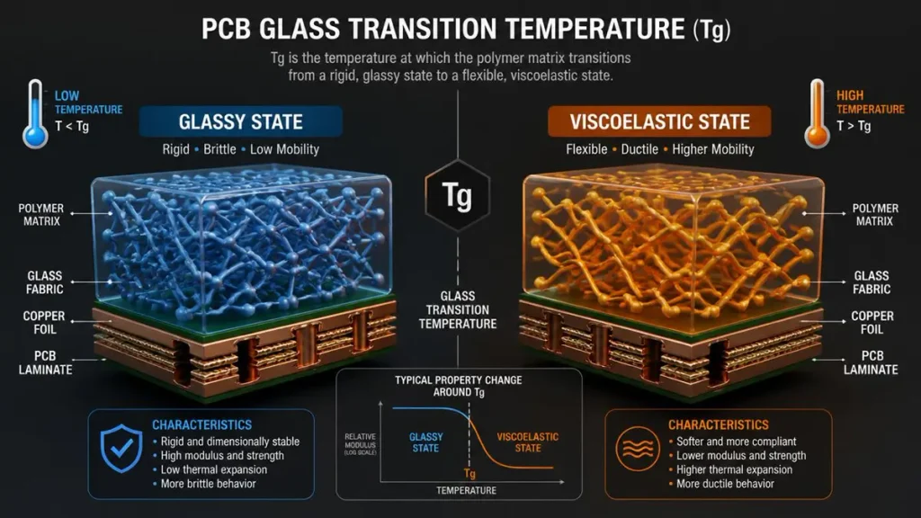
PCB Glass Transition Temperature (Tg): Glassy State vs. Viscoelastic State
PCB glass transition temperature, or PCB Tg, describes the thermal transition behavior of the resin system used in a laminate. It is normally reported as a temperature obtained by a specified test method, rather than as a universal “maximum safe temperature” for the finished circuit board.
A PCB laminate contains a resin system reinforced by materials such as glass fiber. When temperature increases, the polymer network absorbs more thermal energy. Below its glass transition region, the resin generally remains relatively rigid. As temperature approaches Tg, molecular mobility increases and the material becomes increasingly viscoelastic.
This matters because the physical behavior of the laminate does not remain constant across the entire temperature range.
A useful engineering model is: Temperature increase → approach Tg → resin behavior changes → CTE behavior changes → thermal‑mechanical stress increases → reliability margin may decrease
The important point is that Tg is a material‑property indicator, not a standalone reliability rating.
What does PCB Tg actually describe?
Tg primarily describes the transition behavior of the polymer matrix. It does not directly tell an engineer:
- The maximum continuous operating temperature
- The maximum reflow temperature
- The decomposition temperature
- The thermal‑cycling lifetime
- The delamination time
- The complete reliability of a finished PCB
Those characteristics require additional material data and application‑specific evaluation.
For example, Panasonic publishes separate values for Tg, Td, Z‑axis CTE and T288 on its circuit‑board materials. One current material family lists Tg values ranging from 133°C to 173°C depending on the laminate grade, while Z‑axis CTE and T288 performance are reported separately.
Therefore, when a supplier states that a PCB uses a “high‑Tg material,” the next question should be: High Tg according to which test method, for which laminate grade, and with what supporting thermal‑reliability data?
What Happens to PCB Materials Below Tg?
Below Tg, the cured resin generally maintains a relatively rigid mechanical state, and its thermal expansion is lower than in the region above Tg.
This does not mean that the laminate stops expanding below Tg.
All PCB materials expand and contract with temperature. The key difference is that the magnitude and behavior of expansion can change significantly as the resin approaches and passes through its glass transition.
Why does the below‑Tg region matter?
In the lower‑temperature region, engineers normally evaluate:
- X/Y CTE
- Z‑axis CTE
- Flexural behavior
- Dimensional stability
- Moisture effects
- Copper‑to‑laminate mechanical interaction
For multilayer boards, dimensional stability is especially important because copper layers, resin systems and glass reinforcement do not all respond identically to temperature.
The result is a composite mechanical system rather than a single homogeneous material.
Does a PCB remain mechanically stable at every temperature below Tg?
Not necessarily.
A board can experience mechanical deformation, thermal stress, moisture‑related effects or other reliability mechanisms without reaching Tg.
Therefore: Below Tg does not mean zero thermal risk.
It simply describes a different material‑behavior region.
What Happens to PCB Materials Near Tg?
As a PCB laminate approaches Tg, the resin system becomes increasingly viscoelastic, and changes in thermal‑mechanical behavior become more significant.
This is one of the most important concepts for understanding PCB thermal reliability.
A common mistake is to imagine Tg as a switch: 169°C → normal 170°C → failure
Real polymer behavior is more gradual.
Tg represents a transition region detected through a defined measurement technique. The exact reported value can vary depending on the method used.
For example, one published laminate specification reports:
- Tg by DMA: 200°C
- Tg by TMA: 170°C
- Td by TGA: 355°C
for the same material system.
This illustrates why engineers should never compare Tg numbers without checking the test method.
Why is the Tg transition region important?
Near Tg, changes in resin behavior can affect:
- Mechanical stiffness
- Dimensional stability
- Z‑axis expansion
- Internal stress
- Plated‑hole stress
- Interlayer interfaces
- Thermal‑cycling behavior
For a high‑layer‑count PCB, even relatively small dimensional changes can accumulate through the thickness of the board.
That is why Tg becomes more relevant when thermal exposure is combined with repeated heating and cooling.
Why Does PCB Glass Transition Temperature Matter?
PCB Tg matters because thermal exposure near or above the resin transition can change the mechanical and expansion behavior of the laminate, affecting the reliability margin of the finished board.
The significance of Tg increases when a design experiences:
- High operating temperatures
- Repeated thermal cycling
- Lead‑free reflow
- Multiple assembly operations
- High layer counts
- Thick multilayer constructions
- Large temperature excursions
- High reliability requirements
How does PCB Tg affect thermal reliability?
Consider a multilayer PCB exposed repeatedly to elevated temperatures.
During heating: PCB temperature rises → laminate expands
During cooling: PCB temperature falls → laminate contracts
Repeated expansion and contraction can create mechanical stress at material interfaces and plated structures.
The risk becomes more important when the material’s Z‑axis expansion increases substantially around the Tg region.
Published material data provides a useful illustration. Panasonic’s R‑1755D high‑Tg material lists a DSC Tg of 163°C, Z‑axis CTE of 43 ppm/°C below the transition region and 236 ppm/°C in the higher‑temperature region, together with a T288 value of 15 minutes. The conventional FR‑4 comparison material in the same table has Tg of 140°C, Z‑axis CTE values of 65 and 270 ppm/°C, and T288 of 1 minute.
These numbers are material‑specific typical data, not universal PCB design limits.
Is PCB Tg the Maximum Operating Temperature?
No. PCB Tg should not be treated as the maximum operating temperature of a circuit board.
This is one of the most important distinctions in PCB material selection.
Suppose a laminate has: Tg = 175°C
It would be incorrect to conclude:
“The PCB can continuously operate at 175°C.”
The actual operating limit depends on the complete material system, component ratings, copper structures, assembly conditions, environmental exposure and reliability requirements.
A published TU‑768 high‑Tg laminate, for example, lists Tg values of 190°C by DMA, 180°C by DSC and 170°C by TMA, while separately identifying a 130°C maximum operating temperature for that material specification.
This provides a useful real‑world example of why: Tg ≠ maximum operating temperature
How should engineers interpret thermal margin?
A better approach is: Maximum expected application temperature < validated material operating capability
while separately evaluating: Tg + CTE + Td + thermal cycling + assembly exposure + reliability requirements
The exact margin should come from the material supplier’s qualification data and the product’s reliability requirements.
How Does PCB Tg Compare With Soldering Temperature?
PCB Tg and soldering temperature describe two different things and should not be directly substituted for each other.
Lead‑free assembly can expose a PCB to temperatures around the high‑200°C range for short periods. That does not mean the board must have a Tg above the reflow peak.
Instead, engineers evaluate whether the laminate can survive the time‑temperature profile and the associated mechanical and chemical stresses.
Why can reflow temperature exceed PCB Tg?
Because Tg is a transition characteristic, not an absolute failure temperature.
A PCB can temporarily experience temperatures above Tg without immediately delaminating or decomposing.
However, repeated high‑temperature exposure can increase reliability stress.
A useful way to think about the assembly process is: Preheat → soak → liquidus → peak temperature → cooling
The board experiences a thermal profile rather than one constant temperature.
IPC technical material has reported simulated lead‑free assembly testing using a target peak of approximately 260°C, with testing after multiple reflow cycles. Such evaluations illustrate why thermal reliability must consider the actual assembly profile rather than Tg alone.
Why do multiple reflow cycles matter?
A prototype may pass one assembly cycle but experience greater stress after:
- Multiple reflow cycles
- Rework
- Connector soldering
- Thermal cycling
- Moisture conditioning
- High‑temperature storage
For this reason, buyers should communicate the expected assembly process when selecting PCB laminate materials.
How Does PCB Tg Affect Z‑Axis Expansion?
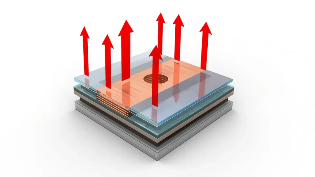
3D Diagram of PCB Z-Axis Thermal Expansion Above Tg
PCB Tg strongly matters to Z‑axis expansion because the laminate’s thickness‑direction CTE can increase substantially in the higher‑temperature region.
This relationship is particularly important for multilayer PCBs and plated‑through structures.
The engineering distinction is: Tg tells you where a major resin‑property transition occurs. Z‑axis CTE tells you how much the material expands in the thickness direction.
These are related but different parameters.
What is Z‑axis CTE?
CTE means coefficient of thermal expansion.
For PCB laminates, engineers normally consider:
- X‑axis CTE
- Y‑axis CTE
- Z‑axis CTE
The Z direction is particularly important because the board contains copper‑plated holes and interconnections extending through its thickness.
Published KB‑6167F material data, for example, specifies:
- Tg by DSC: 175°C typical
- Z‑axis CTE below Tg: 40 ppm/°C typical
- Z‑axis CTE in the higher‑temperature region: 230 ppm/°C typical
- Z‑axis expansion from 50–260°C: 2.6% typical
Again, these figures describe a particular laminate and should not be copied as generic values for all FR‑4 or high‑Tg materials.
Why can Z‑axis expansion increase around Tg?
The resin matrix becomes more compliant as it approaches and passes through the transition region.
Consequently, the composite laminate can exhibit significantly greater thickness‑direction expansion.
That expansion creates additional mechanical movement between: Copper plating ↔ resin ↔ glass reinforcement ↔ adjacent layers
Repeated temperature cycles can therefore increase mechanical fatigue in plated structures.
How Does PCB Tg Affect Plated‑Through‑Hole Reliability?
Tg influences plated‑through‑hole reliability indirectly through the thermal expansion behavior of the laminate.
A plated‑through hole is mechanically connected to multiple PCB layers.
During a temperature excursion: Laminate expands ↓ Copper‑plated barrel experiences mechanical interaction ↓ Heating/cooling repeats the stress cycle ↓ Potential fatigue accumulates
This is why a high‑reliability PCB specification should not stop at: “Tg ≥ 170°C.”
The more useful material evaluation includes:
- Tg
- Z‑axis CTE
- Td
- Thermal stress resistance
- T260/T288
- Copper adhesion
- Thermal cycling data
- Moisture‑conditioned performance
IPC technical literature comparing high‑Tg materials with conventional high‑Tg FR‑4 demonstrates that differences in Z‑axis CTE can accompany differences in thermal‑cycling and reliability performance.
How Does PCB Tg Relate to Delamination?
PCB Tg can influence delamination risk, but Tg alone does not determine whether a PCB will delaminate.
Delamination is a system‑level failure mechanism involving material interfaces, thermal exposure, moisture and manufacturing quality.
A simplified relationship is: Thermal exposure → resin expansion / contraction → interfacial stress → repeated thermal loading → potential delamination
What other factors influence PCB delamination?
Engineers should also consider:
- Resin system
- Laminate construction
- Moisture absorption
- Copper adhesion
- Thermal history
- Lamination quality
- Voids
- Material compatibility
- Number of thermal excursions
- Reflow profile
Therefore, it is technically incorrect to state:
“Higher Tg means the PCB cannot delaminate.”
A better engineering statement is:
A suitable Tg can provide additional thermal margin, but delamination resistance must be evaluated using the complete material and process system.
What Is the Difference Between Tg, Td, T260 and T288?
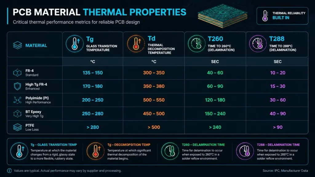
PCB Material Thermal Properties Comparison: Tg, Td, T260, and T288
Tg, Td, T260 and T288 are different thermal‑performance indicators and should not be treated as interchangeable specifications.
| Property | Meaning | Engineering Use |
|---|---|---|
| Tg | Glass transition temperature | Indicates resin transition behavior |
| Td | Thermal decomposition temperature | Indicates onset of significant thermal decomposition under a defined test |
| T260 | Delamination resistance at 260°C under a defined method | Evaluates thermal reliability under specified conditions |
| T288 | Delamination resistance at 288°C under a defined method | Evaluates higher‑temperature thermal resistance |
| Z‑axis CTE | Thickness‑direction thermal expansion | Helps evaluate thermal‑mechanical stress |
Material manufacturers publish these values separately.
For example, Panasonic’s R‑1755E data lists Tg 133°C, Td 370°C, Z‑axis CTE values of 42 ppm/°C below the transition region and 250 ppm/°C in the higher‑temperature region, and T288 of 25 minutes under its stated test conditions.
A separate TU‑872‑LK specification reports Tg values of 220°C DMA, 200°C DSC and 190°C TMA, together with Td of 340°C and separate T260/T288/T300 performance.
These examples demonstrate why a procurement specification should identify both the property and test method.
Does a Higher Tg Always Mean Better PCB Thermal Reliability?
No. Higher Tg can improve thermal margin, but a higher Tg value alone does not guarantee better PCB reliability.
This is a critical engineering distinction.
A PCB material with higher Tg may still have problems if the design or manufacturing process produces:
- Excessive Z‑axis expansion
- Poor copper adhesion
- Weak interfaces
- Moisture‑related degradation
- Poor lamination
- Inadequate plated‑hole reliability
- Excessive thermal cycling stress
For example, Panasonic’s published material data shows that different laminate grades can have substantially different combinations of Tg, Td, Z‑axis CTE and T288.
Therefore, the correct material‑selection question is not: “Which PCB has the highest Tg?”
It is: “Which laminate provides the required thermal margin and reliability under our actual temperature profile?”
How Should Engineers Choose PCB Tg?
Choose PCB Tg from the application’s complete thermal and reliability profile rather than selecting the highest available Tg.
A practical evaluation should begin with five questions.
1. What is the maximum operating temperature?
Determine the actual temperature at the PCB location, not simply the ambient temperature.
For example: Ambient temperature ≠ PCB hotspot temperature
Power components, processors, LEDs and high‑current copper structures can create localized thermal gradients.
2. How long is the board exposed to elevated temperature?
A short thermal excursion and continuous high‑temperature operation create different reliability conditions.
Consider:
- Seconds
- Minutes
- Hours
- Continuous operation
- Repeated thermal cycles
3. What assembly temperature will the PCB experience?
Define:
- Reflow peak
- Number of reflow cycles
- Rework exposure
- Soldering process
- Preconditioning
4. Is Z‑axis reliability important?
For multilayer boards, evaluate: Tg + Z‑axis CTE + plated‑through‑hole reliability
rather than Tg alone.
5. What reliability evidence is required?
Depending on the application, the material qualification may require:
- Thermal stress testing
- T260/T288 data
- Thermal cycling
- Moisture conditioning
- Insulation reliability
- Plated‑through‑hole reliability
What Should PCB Buyers Ask About PCB Glass Transition Temperature?
A PCB RFQ should identify the exact laminate grade and required thermal properties, rather than simply requesting “high‑Tg FR‑4.”
At minimum, ask the PCB manufacturer for:
- Laminate manufacturer
- Exact material grade
- Tg value
- Tg test method
- Td
- Z‑axis CTE
- T260/T288 where applicable
- Maximum application temperature
- Thermal cycling requirements
- Reflow exposure
- Relevant material datasheet
Why does the test method matter?
Tg is not always reported using the same technique.
Common methods include:
- DSC — Differential Scanning Calorimetry
- TMA — Thermomechanical Analysis
- DMA — Dynamic Mechanical Analysis
The same material can produce different numerical Tg values depending on the method.
For example, the TU‑768 specification reports 190°C by DMA, 180°C by DSC and 170°C by TMA.
Consequently, comparing: Material A: Tg 180°C
with: Material B: Tg 175°C
without identifying the test method may produce a misleading conclusion.
How Does Hongda Circuit Approach PCB Tg Selection?
At Shenzhen Hongda Circuit Technology Co., Ltd., PCB material selection is evaluated as part of the engineering specification rather than as an isolated Tg number.
Our manufacturing and engineering capabilities cover high‑reliability multilayer, high‑speed, HDI and other complex PCB structures, with current capability information published on our official technology and capability pages.
For projects where thermal reliability is important, the engineering review can consider: Application temperature ↓ Material Tg ↓ Z‑axis CTE ↓ Stackup construction ↓ Thermal exposure ↓ Reliability requirement
This approach is particularly useful when a board will experience repeated reflow, high‑temperature operation or severe thermal cycling.
What manufacturing technologies support thermal‑reliability control?
For complex PCB construction, Hongda’s current published capability includes precision lamination, LDI imaging, laser drilling, HDI structures, fine‑line processing and inspection technologies.
These processes do not “increase Tg” themselves.
Their role is different: Material selection establishes the thermal property. Manufacturing process control helps preserve the intended structure and reliability of the finished PCB.
This distinction is important when qualifying a PCB supplier.
PCB Glass Transition Temperature FAQ
What is a good Tg for a PCB?
There is no single Tg value that is correct for every PCB. The required Tg depends on operating temperature, assembly exposure, thermal cycling, material construction and reliability requirements. A material around 150°C may be appropriate for one application, while high‑temperature or high‑reliability designs may require a higher‑Tg laminate.
Is PCB Tg the maximum operating temperature?
No. Tg indicates a resin‑property transition and should not automatically be used as the continuous operating‑temperature limit. The material datasheet and application‑specific reliability requirements should determine the appropriate operating range.
How does PCB Tg affect Z‑axis expansion?
The resin’s thermal expansion in the Z direction can increase significantly in the temperature region above Tg. Greater Z‑axis movement can increase mechanical stress on plated‑through holes and other vertical interconnect structures during thermal cycling.
What should I ask a PCB manufacturer about Tg?
Ask for the exact laminate grade, Tg value, test method, Z‑axis CTE, Td and relevant T260/T288 or thermal‑cycling data. Also provide the expected operating temperature, assembly/reflow profile and reliability requirements so the manufacturer can recommend a suitable material system rather than simply quoting the highest available Tg
Final Engineering Perspective on PCB Tg
PCB glass transition temperature is best understood as one part of a thermal‑reliability system.
The most useful engineering relationship is: Tg → resin transition → CTE behavior → thermal‑mechanical stress → interconnect reliability
Tg tells engineers when a major change in polymer behavior occurs. It does not independently define:
- Maximum operating temperature
- Reflow capability
- Thermal decomposition
- Delamination resistance
- Plated‑hole lifetime
For a reliable PCB specification, Tg should therefore be reviewed together with Z‑axis CTE, Td, T260/T288, thermal exposure and application‑specific reliability requirements.
The most important procurement principle is simple:
Do not select a PCB laminate because it has the highest Tg. Select a material system whose documented thermal properties match the actual temperature profile and reliability requirements of the product.
For engineering teams developing a new multilayer, HDI or high‑reliability PCB, Shenzhen Hongda Circuit Technology can support the material‑selection discussion before fabrication begins.
Ask Our PCB Engineers About Material Selection.
About Author
David Chen https://www.linkedin.com/in/pcbcoming
David Chen boasts an extensive professional background in PCBA manufacturing, PCBA testing, and PCBA optimization, with specialized expertise in high-precision PCBA fault analysis and rigorous PCBA reliability testing. The author has worked with high-layer-count server PCB fabrication, ultra-low-loss backplane stackups, and thermo-mechanical reliability optimization for AI infrastructure projects involving 112G and 224G PAM4 architectures. Skilled in complex circuit design and cutting-edge advanced PCB manufacturing processes, he delivers solutions that elevate product durability and performance across industrial applications. His technical articles focusing on PCBA manufacturing workflows and testing methodologies are widely cited by industry peers, research institutions, and technical platforms, solidifying his reputation as a recognized technical authority in the global circuit board manufacturing sector.