
Data Center Switch PCB: Manufacturing, Material Selection, and Supplier Qualification
A Data Center Switch PCB connects switching ASICs, high-speed SerDes interfaces, network ports, power distribution circuits, and management components in data center networking equipment. Reliable manufacturing requires a carefully engineered stackup, suitable low-loss materials, controlled impedance, appropriate via structures, and verifiable electrical performance. For OEM buyers, selecting the right PCB manufacturer also means evaluating material traceability, fabrication tolerances, quality documentation, production consistency, and the ability to support the project from prototype through volume production.
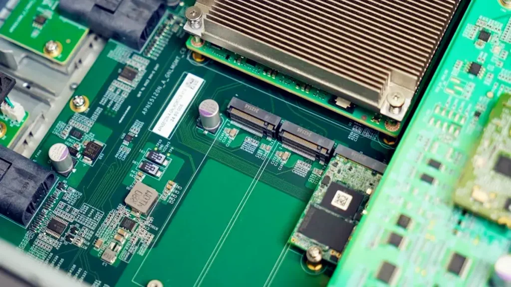
High-speed data center switch PCBs support high-bandwidth Ethernet connectivity and demanding signal-integrity requirements.
What Makes Data Center Switch PCB Manufacturing Different from Standard PCB Manufacturing?
Data Center Switch PCB manufacturing must address high-speed signal transmission, dense component routing, power delivery, and mechanical reliability within a single board architecture. The required manufacturing processes depend on the switching platform, interface specifications, board dimensions, and electrical acceptance criteria.
How Do Switch Mainboards, Line Cards, and Backplanes Differ?
Different switch board types have different manufacturing priorities.
| Board type | Primary engineering requirements | Manufacturing considerations |
|---|---|---|
| Switch mainboard | ASIC connectivity, SerDes routing, power distribution | Multilayer stackup, impedance control, dense BGA fan-out |
| Switch line card | High-speed network interfaces, connector transitions | Insertion loss, via design, connector alignment |
| Switch backplane | High-speed inter-board connections and mechanical interfaces | Board thickness, connector fit, signal loss, backdrilling where required |
| Management board | Control interfaces, monitoring, and lower-speed communication | Cost-effective stackup and appropriate electrical testing |
| Power distribution board | High-current delivery and thermal performance | Copper thickness, conductor resistance, insulation, and temperature rise |
These categories can overlap depending on the platform architecture. The final requirements should therefore be established from the actual circuit design rather than inferred from the board name alone.
How Do Switching ASICs and SerDes Interfaces Affect PCB Requirements?
Switching ASICs concentrate large numbers of high-speed connections into dense BGA footprints. Routing these connections requires careful escape routing, reference-plane continuity, controlled-impedance structures, and suitable via transitions.
The interface specification determines the relevant signaling rate, channel bandwidth, and electrical performance requirements. For example, 400G and 800G Ethernet systems can use different combinations of lane counts and signaling rates. A system-level data rate should not be confused with the signaling rate of an individual differential pair.
Before fabrication, engineers should confirm:
- ASIC package dimensions and BGA pitch.
- SerDes interface requirements and channel topology.
- Target impedance and acceptable tolerance.
- Channel insertion-loss budget.
- Connector and via-transition models.
- Power distribution and thermal constraints.
These inputs allow the fabricator to assess whether the proposed stackup and manufacturing processes are appropriate for the design.
How Should Buyers Specify a Data Center Switch PCB Stackup?
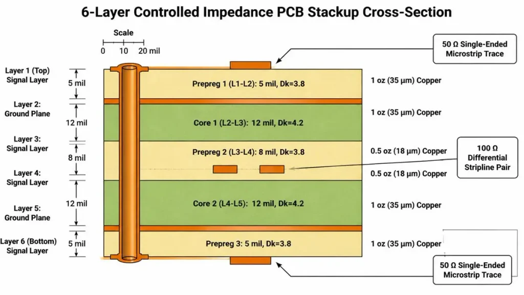
Data Center Switch PCB Multilayer Stackup Design
A suitable Data Center Switch PCB stackup must balance routing density, electrical performance, power distribution, mechanical stability, and manufacturing feasibility. Layer count should be determined by the actual design requirements rather than a universal rule for all data center switches.
How Should Layer Count Be Determined?
The number of layers depends on the number of high-speed routing channels, ASIC escape requirements, power and ground planes, board dimensions, and via architecture.
A higher layer count does not automatically produce better signal integrity. Poorly selected dielectric thicknesses, unsuitable reference planes, or excessive via transitions can still compromise electrical performance.
During stackup planning, engineers should define:
- Total layer count and layer functions.
- Core and prepreg materials.
- Finished board thickness and tolerance.
- Copper thickness on each layer.
- Controlled-impedance layers.
- Blind, buried, and through-via structures.
- Backdrilling requirements, if applicable.
- Mechanical and warpage limits.
When Are HDI, Blind Vias, and Buried Vias Necessary?
High-density interconnect (HDI) construction can help route fine-pitch ASIC connections and improve routing density. Blind and buried vias may reduce the routing burden associated with conventional through-hole structures.
However, HDI adds process complexity. Sequential lamination, microvia formation, copper filling, registration, and reliability requirements must be evaluated together.
Before selecting an HDI structure, buyers should ask the manufacturer to review the proposed via architecture, aspect ratios, pad dimensions, lamination sequence, and applicable reliability requirements.
Learn more about high-speed PCB manufacturing and how multilayer construction supports demanding electrical designs.
How Can Stackup Symmetry Reduce Warpage Risk?
An appropriately balanced stackup can reduce residual stress caused by differences in copper distribution, dielectric construction, and thermal expansion.
The design review should consider copper balance, material compatibility, board thickness, lamination conditions, and the mechanical requirements of connectors and enclosures. Warpage acceptance criteria should be specified in the fabrication documentation when flatness is critical to assembly.
Which Low-Loss PCB Materials Are Suitable for 400G and 800G Data Center Switches?
The appropriate PCB material is the one that meets the complete channel’s electrical requirements while remaining compatible with the design’s manufacturing, reliability, and cost constraints. Material selection should consider dielectric properties, copper roughness, dielectric thickness, glass construction, and the intended operating frequency.
How Do Dk and Df Affect High-Speed Switch PCB Performance?
The dielectric constant (Dk) affects signal propagation and transmission-line geometry. The dissipation factor (Df) describes dielectric energy loss under specified measurement conditions.
Both properties influence high-speed circuit behavior, but neither should be evaluated in isolation. Actual channel performance also depends on copper roughness, conductor geometry, glass weave, connectors, vias, and total interconnect length.
Buyers should request material data relevant to the intended frequency range and verify that the selected construction supports the project’s insertion-loss budget.
How Should Engineers Compare Megtron 6, Megtron 7, and Alternative Laminates?
Materials such as Panasonic Megtron 6, Megtron 7, and other low-loss laminate systems may be candidates for demanding high-speed designs. The appropriate selection depends on the specific material grade, construction, frequency-dependent properties, availability, and cost.
A meaningful comparison should include:
| Evaluation factor | What buyers should verify |
|---|---|
| Dielectric performance | Dk and Df under relevant test conditions |
| Copper foil | Roughness profile and compatible copper type |
| Dielectric thickness | Available constructions and manufacturing tolerances |
| Thermal performance | Glass-transition and decomposition properties where relevant |
| Manufacturing compatibility | Lamination, drilling, plating, and registration requirements |
| Supply continuity | Availability, batch traceability, and approved alternatives |
| Total cost | Material price, fabrication complexity, yield, and testing |
Do not choose a laminate based only on its brand name or a single Df value. The complete stackup and channel must be evaluated.
When Can a Hybrid Stackup Reduce Material Costs?
A hybrid stackup combines different laminate systems within one board. It may reduce material cost when expensive low-loss materials are limited to the layers that need them.
However, hybrid construction introduces additional considerations, including material compatibility, resin behavior, thermal expansion, lamination requirements, and dielectric consistency.
Before approving a hybrid stackup, the design and manufacturing teams should confirm that the proposed material arrangement meets the electrical budget and can be fabricated reliably.
How Should Buyers Control Material Substitution Risks?
Material substitutions can affect impedance, insertion loss, dimensional stability, and reliability. Buyers should identify approved material grades in the procurement specification and establish a formal approval process for substitutions.
Request material identification, applicable certificates of conformance, batch traceability, and notification of relevant material or process changes. Any substitute should be evaluated against the original design requirements before production approval.
How Can PCB Fabrication Affect High-Speed Signal Integrity?
High-speed signal integrity depends on the complete electrical channel, including the ASIC package, PCB traces, vias, connectors, and receiving interface. A controlled-impedance PCB alone cannot guarantee that the assembled system will meet its performance target.
How Should Engineers Establish a Channel Insertion-Loss Budget?
The channel budget should allocate allowable loss across all relevant interconnect elements. These can include package transitions, PCB routing, vias, connectors, cables, and other components in the signal path.
The PCB manufacturer needs the relevant design constraints to assess material selection, routing geometry, dielectric thickness, and via structures.
Where possible, the design team should provide the target frequency range, channel length, reference stackup, impedance requirements, and available simulation or measurement data.
Why Are Differential Impedance and Return-Path Continuity Important?
Differential impedance must be controlled to reduce unwanted reflections at impedance discontinuities. Return-path continuity is also important because changes in reference-plane geometry can increase parasitic effects and electromagnetic coupling.
A manufacturable impedance specification should identify:
- The target impedance.
- The applicable tolerance.
- The controlled layers and signal structures.
- The reference-plane arrangement.
- The trace geometry or approved stackup.
- The required test method and reporting format.
For example, 100-ohm differential impedance is common in many high-speed interfaces, but the actual target must come from the project’s electrical specification.
See PCBKR’s controlled-impedance PCB manufacturing information for additional guidance on specifying impedance requirements for fabrication.
When Is Via Backdrilling Required?
Backdrilling removes unused portions of plated through-hole vias that can create unwanted stubs. These stubs may cause reflections and resonances that degrade high-frequency channel performance.
Backdrilling should be specified when the channel analysis indicates that via stubs contribute unacceptable electrical discontinuities.
The manufacturing package should define the affected vias, drill direction, target depth, residual-stub criterion, and applicable tolerances. The fabricator should confirm feasibility before production.
Backdrilling should not be treated as mandatory for every high-speed signal. Its necessity depends on the via geometry, signaling requirements, stackup, and channel budget.
How Can TDR and VNA Measurements Validate PCB Performance?
Time-domain reflectometry (TDR) is used to evaluate impedance behavior along a transmission path or suitable test structure. A vector network analyzer (VNA) can measure frequency-dependent characteristics such as insertion loss and return loss.
These measurements serve different purposes.
A TDR report does not, by itself, establish insertion-loss compliance. Similarly, a VNA result is meaningful only when the test structure, frequency range, calibration, fixtures, and measurement method are appropriate.
For procurement, the test plan should identify the required measurements, acceptance limits, reporting format, and whether results are required for qualification samples, production coupons, or each production lot.
How Should Data Center Switch PCBs Handle High ASIC Power and Thermal Stress?
High-power switching ASICs require a power distribution network that delivers current within voltage-drop and noise limits while supporting the system’s thermal design. PCB copper, component placement, vias, package interfaces, and system cooling must be evaluated together.
How Do Copper Planes Affect Voltage Drop and Current Distribution?
Copper thickness, plane geometry, path length, and via arrangement affect conductor resistance and current distribution.
Increasing copper thickness may reduce resistance, but it also changes etching, spacing, thermal behavior, and manufacturing cost. The correct copper weight should follow the power distribution analysis and fabrication constraints.
Buyers should provide the relevant current requirements, voltage limits, copper specifications, and temperature-rise criteria rather than requesting a generic heavy-copper construction.
When Are Thermal Vias or Embedded Copper Coins Appropriate?
Thermal vias can provide conductive paths through the PCB. Embedded copper coins may provide a more direct thermal path in certain specialized constructions.
Neither approach is universally necessary. Selection depends on package design, heat flux, board architecture, assembly requirements, reliability, and the available cooling system.
The manufacturer should review the proposed structure for fabrication feasibility and compatibility with the board’s mechanical and electrical requirements.
How Can Thermal Stress and Board Warpage Be Controlled?
Thermal stress can affect board flatness, plated structures, solder joints, and connector alignment. Relevant controls include balanced stackups, compatible materials, appropriate lamination profiles, copper distribution, and defined inspection criteria.
Where the application requires it, the project qualification plan should identify thermal cycling, thermal stress, warpage measurement, and other reliability tests applicable to the product.
Which Manufacturing Processes and Quality Controls Matter Most for Data Center Switch PCBs?
Reliable fabrication requires coordinated control of imaging, lamination, drilling, plating, layer registration, surface finishing, and electrical verification. The suitability of these processes must be demonstrated against the actual board specification.
How Does High-Layer-Count Lamination Affect PCB Reliability?
High-layer-count boards require careful control of material alignment, dielectric thickness, resin flow, copper distribution, and lamination conditions.
Inconsistent processing can affect dimensional stability, registration, and finished-board geometry. For complex designs, manufacturing engineering should review the stackup and lamination sequence before the design is released.
How Are Drilling, Backdrilling, and Plated Through-Hole Quality Verified?
Drilling quality affects hole geometry, wall condition, plating integrity, and dimensional accuracy. Backdrilling adds depth-control requirements and must preserve the required electrical connections.
Depending on the specification, verification may include drill records, dimensional inspection, microsection analysis, and electrical testing.
The acceptance criteria should be agreed upon before production rather than inferred from a manufacturer’s general capability statement.
Which Microsection and Reliability Tests Should Buyers Request?
Microsection analysis can be used to examine internal construction, plated hole walls, copper thickness, and relevant structural features.
Additional reliability tests should be selected according to the design, applicable standards, product requirements, and qualification plan. Buyers should distinguish routine production inspection from specialized qualification testing.
How Are Material Traceability and Process Changes Managed?
For production programs, traceability supports investigation of defects and control of approved materials and manufacturing revisions.
The procurement specification should identify the required production records, material documentation, change-notification process, and approval authority. This is particularly important when a material or process change could affect electrical performance or reliability.
Which Quality Tests Should Buyers Require from a Data Center Switch PCB Manufacturer?
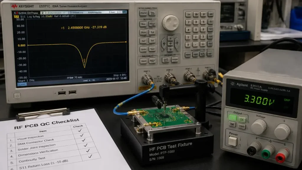
Data Center Switch PCB Impedance Testing
Buyers should define an inspection and test plan that maps each electrical, mechanical, and structural requirement to an appropriate verification method. A generic statement that a board has passed electrical testing is not sufficient to establish high-speed performance.
| Verification item | What it evaluates | What to request |
|---|---|---|
| Impedance testing | Impedance of specified test structures | Target values, tolerances, and TDR results |
| Insertion-loss testing | Frequency-dependent transmission loss | Test curves, frequency range, and measurement method |
| Microsection analysis | Internal construction and plated features | Cross-section records and applicable acceptance criteria |
| Electrical continuity and isolation | Net connectivity and unintended shorts | Test coverage and production results |
| Dimensional inspection | Board dimensions, thickness, and relevant tolerances | Inspection records |
| Material traceability | Material identity and production history | Batch records and applicable material documentation |
| Reliability qualification | Performance under specified stress conditions | Test plan, results, and acceptance criteria |
Not every project requires every test on every production lot. The appropriate scope should be agreed upon by the engineering, quality, and procurement teams.
What Determines Data Center Switch PCB Manufacturing Cost and Lead Time?
Data Center Switch PCB cost and lead time depend on the complete fabrication specification, material availability, process complexity, inspection requirements, order quantity, and production schedule. An accurate quotation requires enough information to assess both engineering feasibility and manufacturing effort.
How Do Layer Count and Low-Loss Materials Affect PCB Cost?
Higher layer counts and specialized laminates can increase material consumption, processing time, and fabrication complexity. The impact depends on the selected stackup, panel utilization, required tolerances, and available material constructions.
Material selection should therefore consider total project cost rather than laminate price alone.
How Do HDI, Backdrilling, and Additional Testing Affect Production?
HDI structures may require additional lamination and microvia processes. Backdrilling adds drilling operations and depth-control requirements. Specialized electrical tests can require dedicated coupons, fixtures, and measurement procedures.
These requirements may affect both cost and lead time. Their impact should be evaluated during DFM and quotation rather than after design release.
How Can Buyers Reduce Cost Without Compromising Signal Integrity?
Useful cost-optimization measures include:
- Selecting the least complex stackup that meets the electrical and mechanical requirements.
- Using specialized laminates only where the channel budget justifies them.
- Avoiding unnecessary sequential lamination and via structures.
- Confirming panel dimensions and material availability early.
- Defining the required test scope before production.
- Resolving DFM issues before releasing the manufacturing data.
- Establishing approved material alternatives where technically acceptable.
Cost reduction should never rely on unapproved material substitutions or relaxation of critical electrical requirements.
What Should Be Planned Before Prototype-to-Production Transfer?
Before moving to volume production, buyers should confirm the approved stackup, material identity, manufacturing revision, inspection plan, electrical acceptance criteria, and required quality records.
The qualification stage should also establish how process changes will be reviewed and how production lots will be evaluated for consistency.
Prototype approval should be based on the project’s acceptance criteria, not solely on the fact that a sample board has been fabricated successfully.
How Can Buyers Qualify a Data Center Switch PCB Manufacturer?
A qualified manufacturer should be able to demonstrate that its materials, processes, inspection methods, and production controls match the requirements of the specific switch design. Buyers should evaluate documented evidence rather than relying on general claims of advanced capability.
Which Fabrication Capabilities Must Be Verified?
Confirm the manufacturer’s ability to process the specified layer count, materials, board thickness, copper weights, via structures, impedance requirements, and mechanical tolerances.
For specialized high-speed projects, also establish whether the manufacturer can support the requested backdrilling and electrical measurement requirements.
Capability limits should be confirmed for the actual design and construction. A machine’s nominal resolution or a general company capability statement does not automatically establish repeatable finished-board performance.
What Test Reports and Quality Documents Should Be Requested?
Depending on the project, buyers may request:
- Approved stackup and fabrication documentation.
- Material identification and applicable certificates.
- Impedance measurement reports.
- Insertion-loss test results, where specified.
- Microsection and plating inspection records.
- Dimensional inspection results.
- Electrical test documentation.
- Relevant qualification and reliability test reports.
- Material and process change-control procedures.
The required documents should be specified in the purchase order or quality agreement.
How Should Buyers Evaluate Prototype and Volume Production Consistency?
Ask how the supplier controls manufacturing revisions, material batches, process parameters, inspection records, and corrective actions.
For demanding applications, define the criteria for engineering samples, pilot builds, and production release before ordering the first prototype. This reduces the risk of discovering late in the project that the production process cannot maintain the approved construction.
What Information Should Be Included in a Data Center Switch PCB RFQ?
A complete RFQ should contain the manufacturing data, electrical targets, mechanical constraints, quantities, schedule, and inspection requirements needed for a meaningful engineering review and quotation.
| RFQ item | Information to provide |
|---|---|
| Application | Mainboard, line card, backplane, or other switch board |
| Manufacturing files | Gerber, ODB++, or IPC-2581, as applicable |
| Stackup | Layer count, layer functions, materials, and dielectric thicknesses |
| Copper | Copper thickness by layer and any special copper requirements |
| Electrical requirements | Impedance targets, tolerances, controlled layers, and relevant interfaces |
| Signal integrity | Insertion-loss targets, frequency range, and specified test requirements |
| Via structures | Through vias, blind vias, buried vias, and backdrill requirements |
| Mechanical requirements | Finished thickness, dimensions, tolerances, and warpage criteria |
| Surface finish | Required finish and applicable acceptance criteria |
| Quantity | Prototype, pilot, and expected production volumes |
| Quality documentation | Inspection, test, traceability, and qualification requirements |
| Delivery | Required delivery date, milestones, and shipment plan |
If some parameters have not yet been finalized, identify them as open engineering items. The manufacturer can then clarify which details are essential for quotation and which require further design review.
How Can Shenzhen Hongda Circuit Technology Support Data Center Switch PCB Projects?
Shenzhen Hongda Circuit Technology Co., Ltd. provides PCB manufacturing services for demanding multilayer, high-speed, and high-density applications. For a data center switch project, the appropriate next step is to review the actual design data, material requirements, electrical specifications, and inspection expectations against the manufacturing processes available for the project.
What Should Be Reviewed Before Manufacturing?
An engineering review should establish:
- The proposed stackup and material system.
- Layer count, copper thickness, and finished board dimensions.
- Impedance requirements and controlled signal layers.
- Via architecture and any backdrilling requirements.
- Relevant mechanical and reliability constraints.
- Required electrical tests and quality documentation.
- Prototype quantities, production expectations, and target delivery dates.
PCBKR’s high-speed PCB manufacturing and high-speed PCB manufacturing guide provide additional information about its high-speed and multilayer manufacturing focus.
Actual process capability, available materials, testing scope, and delivery commitments should be confirmed during the project review.
How Can OEM Buyers Request a Data Center Switch PCB Quote?
To request a manufacturing review, prepare the latest fabrication files, stackup requirements, impedance specifications, material preferences, order quantity, and delivery target.
If insertion-loss testing, backdrilling verification, microsection inspection, or other specialized documentation is required, include those requirements in the RFQ.
Request a Data Center Switch PCB Manufacturing Review
Contact Shenzhen Hongda Circuit Technology Co., Ltd. to discuss your project requirements.
- Website: https://www.pcbkr.com/
- Email: pcb@pcbkr.com
Submit your PCB specifications for a manufacturing feasibility review and quotation based on your actual design requirements.
Frequently Asked Questions About Data Center Switch PCBs
What Is a Data Center Switch PCB?
A Data Center Switch PCB is a printed circuit board used in network switching equipment to connect switching ASICs, high-speed interfaces, power circuits, and management components. Its construction depends on the system architecture and electrical requirements.
How Many Layers Does a Data Center Switch PCB Need?
The required layer count depends on routing density, ASIC package design, power distribution, board dimensions, and signal-integrity requirements. The final stackup should be established through engineering design and manufacturing review.
Which PCB Material Is Best for an 800G Network Switch?
The appropriate material depends on the channel insertion-loss budget, frequency range, copper roughness, dielectric properties, and fabrication constraints. Low-loss or ultra-low-loss laminates may be appropriate for critical signal paths, but the entire channel must be evaluated.
Is Standard FR-4 Suitable for Data Center Switch PCBs?
Standard FR-4 may be suitable for lower-speed management circuits or other non-critical sections when its electrical performance meets the design requirements. High-speed channels may require lower-loss materials, depending on their channel budget and operating frequency.
When Is Backdrilling Required for High-Speed PCBs?
Backdrilling is considered when unused via stubs create unacceptable reflections or resonances. Its necessity and target residual-stub length should be established through channel analysis and confirmed with the PCB manufacturer.
What Impedance Is Commonly Used for Data Center Switch PCBs?
A 100-ohm differential target is common for many high-speed interfaces, but the actual target and tolerance depend on the interface specification and system design. The fabrication drawing should define the controlled structures and verification method.
What Affects Data Center Switch PCB Manufacturing Cost?
Major cost factors include layer count, laminate selection, board dimensions, copper thickness, HDI complexity, backdrilling, special testing, production quantity, and delivery requirements.
Conclusion
Data Center Switch PCB manufacturing requires coordinated decisions across stackup design, low-loss material selection, signal integrity, power delivery, fabrication, and quality verification. The best manufacturing partner is not simply the supplier with the largest advertised layer count or the lowest initial quotation. It is the supplier that can demonstrate a suitable process, verify the required electrical and mechanical characteristics, control production changes, and provide the evidence needed for project acceptance.
For OEM buyers developing data center networking equipment, a complete RFQ and an early manufacturing review can help identify fabrication risks, clarify testing requirements, and improve the transition from prototype to production.
Contact Shenzhen Hongda Circuit Technology Co., Ltd. at pcb@pcbkr.com or visit https://www.pcbkr.com/ to discuss your PCB manufacturing requirements.
About Author
David Chen LinkedIn Profile
David Chen is a Senior RF/PCB Process Engineer at Shenzhen Hongda Circuit Technology Co., Ltd., with over 12 years of experience in high-frequency PCB fabrication, impedance-controlled stack-up design, and Rogers/PTFE laminate processing. He also boasts an extensive professional background in PCBA manufacturing, PCBA testing, and PCBA optimization, with specialized expertise in high-precision PCBA fault analysis and rigorous PCBA reliability testing. The author has worked with high-layer-count server PCB fabrication, ultra-low-loss backplane stackups, and thermo-mechanical reliability optimization for AI infrastructure projects involving 112G and 224G PAM4 architectures. Skilled in complex circuit design and cutting-edge advanced PCB manufacturing processes, he delivers solutions that elevate product durability and performance across industrial applications. His technical articles focusing on PCBA manufacturing workflows and testing methodologies are widely cited by industry peers and technical platforms, and have gained attention and recognition from industry colleagues.