How Should Robotics OEMs Specify a Motor Controller PCB for Manufacturing?
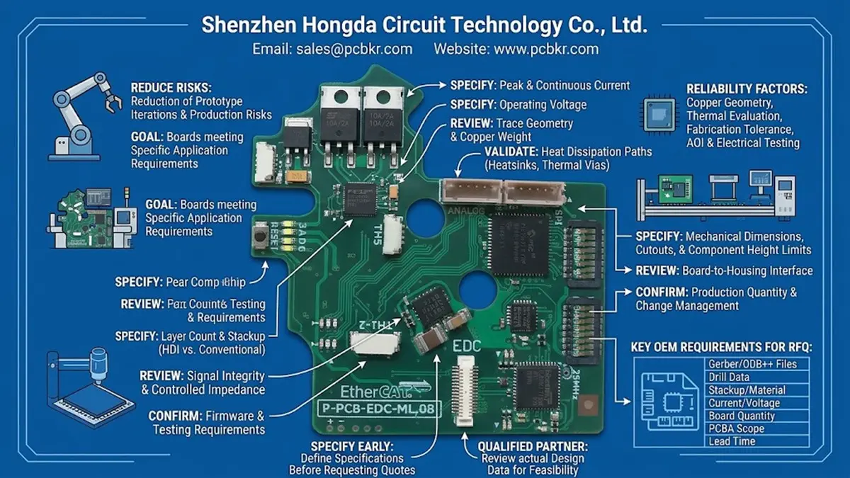
A motor controller PCB for robotics must match the drive circuit’s electrical, thermal, mechanical, and manufacturing requirements. Robotics OEMs should define operating current, voltage, copper weight, stackup, board thickness, component layout constraints, and testing requirements before requesting a quote. A qualified PCB manufacturer should review the actual design data and confirm manufacturing feasibility rather than relying on generic capability claims.
For robotics companies developing collaborative robots, robotic arms, autonomous platforms, and precision motion-control systems, choosing the right manufacturing partner can help reduce prototype iterations and production risks. The goal is not simply to manufacture a circuit board, but to produce a board that meets the requirements of the intended motor-control application.
Shenzhen Hongda Circuit Technology Co., Ltd. supports custom PCB manufacturing and PCBA projects. This guide explains what robotics OEMs should specify, what manufacturing factors deserve attention, and what information to prepare before requesting a motor controller PCB quotation.
What Does a Motor Controller PCB Need to Support in a Robotics System?
A motor controller PCB must provide the electrical connections, component mounting, signal routing, and thermal performance required by its specific motor-drive architecture. Its requirements depend on the motor type, drive topology, operating environment, and control system.
Robotics applications can have substantially different PCB requirements. A compact joint controller for a collaborative robot may prioritize space constraints and encoder interfaces, while a mobile robot traction controller may require careful evaluation of high-current paths, power components, and heat dissipation.
How Do Motor Drivers and Servo Drive PCBs Differ?
Although these terms sometimes overlap, they can describe different levels of a motion-control system.
- Motor driver PCB: Typically supports the circuitry that switches and regulates power delivered to a motor. Depending on the design, it may include MOSFETs, gate drivers, current-sensing components, and protection circuitry.
- Servo drive PCB: May combine power conversion, feedback acquisition, control interfaces, and other functions required for closed-loop motion control.
- Motor control and interface PCB: May handle command signals, encoder communication, sensor inputs, or connections to a separate power stage.
The actual partitioning depends on the OEM’s architecture. Some products integrate control logic and power electronics on one board; others separate them to simplify thermal management, electrical isolation, maintenance, or mechanical integration.
This distinction matters when requesting a quotation. A PCB supplier needs to know whether the project involves a low-voltage control board, a power-stage PCB, or a more integrated assembly.
Which Robotics Applications Use Motor Controller PCBs?
Motor controller PCBs are used in several robotics product categories.
| Robotics application | Typical PCB considerations | Information to clarify before manufacturing |
|---|---|---|
| Collaborative robot joints | Compact layout, motor drive circuitry, encoder connections | Board envelope, interfaces, power architecture |
| Robotic arms | Motion-control signals, power distribution, mechanical integration | Axis configuration, connector locations, vibration environment |
| Autonomous mobile robots | Traction motor power, sensing, communication interfaces | Continuous and peak current, battery voltage, thermal conditions |
| Industrial robotic actuators | Power switching, feedback, electrical robustness | Operating environment, duty cycle, reliability requirements |
| Robotic grippers | Compact motor control, sensor interfaces | Available space, actuator type, connector and cable arrangement |
| Prototype robotics platforms | Design flexibility and engineering revisions | Prototype quantity, revision status, expected production volume |
The PCB design must be evaluated in the context of the complete application. A board that works in a low-duty-cycle laboratory prototype may require further thermal or electrical validation before it can be used in a production robot.
For projects focused on robot integration and manufacturing, see our collaborative robot PCB manufacturing page.
Which PCB Specifications Should Robotics OEMs Define Before Quotation?
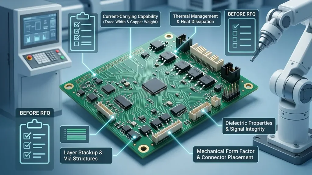
Guide to Specifying Motor Controller PCBs for Robotics OEMs Before Requesting a Quote
Robotics OEMs should provide the electrical, physical, material, and manufacturing requirements that determine whether a PCB can be fabricated and assembled correctly. The more complete the specification, the easier it is for a manufacturer to identify process risks and prepare a meaningful quotation.
How Should OEMs Specify Current, Voltage, and Copper Weight?
Copper weight is an important consideration for motor controller PCBs because power-stage circuits may carry substantial current. However, selecting copper weight based on current alone is not sufficient.
Current-carrying capability also depends on trace width, copper thickness, allowable temperature rise, surrounding copper, layer arrangement, airflow, board construction, and the duration of the load.
Common nominal copper weights include:
| Nominal copper weight | Approximate copper thickness | Potential application considerations |
|---|---|---|
| 1 oz/ft² | 35 µm | Signal routing and some lower-current power circuits |
| 2 oz/ft² | 70 µm | Power routing where the design benefits from thicker copper |
| 3 oz/ft² | 105 µm | Selected high-current applications requiring careful fabrication and layout review |
These are nominal values, not guaranteed finished conductor thicknesses at every location. Plating, etching, and the selected manufacturing process affect the final conductor geometry.
For a motor controller PCB, OEMs should distinguish between:
- Continuous operating current.
- Peak current and its duration.
- Startup or acceleration current.
- Maximum allowable conductor temperature.
- Ambient temperature and cooling conditions.
- Required voltage isolation and clearance.
- Available copper area and routing space.
A practical recommendation: Provide the expected current profile and thermal limits along with the Gerber or ODB++ files. The manufacturer and design engineer can then review the proposed copper weight and conductor geometry against the actual application.
For projects requiring thicker copper conductors, see our heavy copper PCB manufacturing page.
When Should a Motor Controller PCB Use a Multilayer or HDI Stackup?
The choice between a two-layer, conventional multilayer, and high-density interconnect (HDI) PCB depends on routing density, electrical requirements, mechanical constraints, and production economics.
A two-layer PCB may be sufficient for a relatively simple controller. A multilayer design can provide additional routing resources and dedicated reference or power planes. HDI construction may be appropriate when fine-pitch components, dense control circuitry, compact connectors, or restricted board dimensions make conventional routing difficult.
| PCB construction | Potential advantages | Important considerations |
|---|---|---|
| Two-layer PCB | Relatively simple construction and routing | Limited routing resources and plane options |
| Conventional multilayer PCB | More routing layers and greater layout flexibility | Stackup, lamination, registration, and cost |
| HDI PCB | Fine routing and compact component integration | Microvia design, fabrication tolerances, and additional process complexity |
| Heavy copper PCB | Supports selected designs requiring thicker copper conductors | Etching, feature geometry, spacing, and manufacturing feasibility |
Not every motor controller needs HDI technology. If the board has sufficient space and conventional routing meets the electrical requirements, a more complex stackup may add cost without providing a meaningful benefit.
Before choosing HDI, confirm the minimum trace width and spacing, via structure, component pitch, board thickness, and layer count. The selected manufacturer should assess whether the proposed construction can be produced consistently.
Learn more about our HDI PCB manufacturing capabilities and applications.
What Mechanical and Material Details Should Be Included?
Motor controller PCBs often need to fit tightly into actuator housings, robot joints, or compact electronic enclosures. Mechanical requirements should therefore be reviewed before the board enters production.
Important details include:
- Finished board dimensions and thickness.
- Mounting-hole positions and tolerances.
- Connector locations and orientation.
- Component height restrictions.
- Cutouts, slots, and edge clearances.
- Board-to-housing interfaces.
- Thermal contact with heatsinks or chassis.
- Required surface finish.
- Operating temperature and environmental conditions.
Material selection should follow the electrical and thermal requirements of the design. Standard FR-4 may be suitable for many control boards, while specific power or high-temperature applications may require a different material system or board construction.
If the design includes high-speed encoder interfaces, sensitive communication links, or demanding signal-integrity requirements, the engineer should also evaluate dielectric properties, impedance requirements, return paths, and routing constraints.
The final material and stackup should be agreed upon before production, particularly when a prototype is intended to transition to repeat manufacturing.
How Can PCB Manufacturing Affect Motor Controller Reliability?
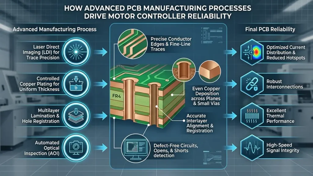
How Advanced PCB Manufacturing Processes Drive Motor Controller Reliability
PCB manufacturing can affect electrical performance, thermal behavior, assembly quality, and long-term reliability. A correct schematic and layout do not eliminate the need to control fabrication tolerances, inspect the finished board, and verify its electrical characteristics.
How Can Copper Geometry Affect Power Distribution?
Power-stage performance depends on the complete current path, including copper geometry, vias, pads, component connections, and return paths.
Narrow conductors, unsuitable via arrangements, or unexpected bottlenecks may create localized resistance and heating. Conversely, increasing copper weight without considering the complete layout may introduce other constraints, including etching limitations, spacing restrictions, and component assembly challenges.
For OEMs, the practical approach is to review the following together:
- The expected continuous and peak current.
- Trace widths and copper thickness.
- Via count, size, and current-path arrangement.
- Copper distribution across the stackup.
- Component-pad and terminal geometry.
- Thermal paths and heat-dissipation arrangements.
Electrical and thermal simulation can help identify potential issues during design, but the assumptions must match the intended operating conditions. Prototype measurements should then verify the design where appropriate.
How Should Thermal Management Be Evaluated?
Motor controllers may contain power MOSFETs, gate drivers, current-sensing components, and other devices that generate heat. Their operating temperatures depend on component losses, switching conditions, PCB copper distribution, airflow, heatsinking, and the surrounding enclosure.
PCB manufacturing and assembly influence whether the intended thermal design can be implemented accurately. However, the PCB alone cannot guarantee acceptable operating temperatures.
OEMs should define:
- Maximum expected ambient temperature.
- Continuous and peak operating conditions.
- Component temperature limits.
- Required thermal interfaces.
- Enclosure and cooling constraints.
- Relevant prototype validation procedures.
If thermal vias, large copper areas, or exposed-pad components are part of the design, their manufacturability and assembly requirements should be reviewed before production.
A prototype thermal test under representative operating conditions is more useful than relying solely on nominal copper weight or a generic PCB current table.
Which Fabrication Defects Should OEMs Discuss With Their Manufacturer?
The inspection plan should reflect the PCB’s complexity, intended use, and reliability requirements.
Potential concerns include:
| Manufacturing concern | Why it matters | Relevant verification |
|---|---|---|
| Open or short circuits | May interrupt or alter electrical connections | Electrical testing and appropriate visual inspection |
| Layer registration problems | Can affect conductor geometry and interlayer connections | Fabrication process controls and applicable inspection |
| Plated-hole defects | May compromise interlayer electrical continuity | Hole-plating process control and relevant verification |
| Etching deviations | Can alter trace width and spacing | Optical inspection and process measurement |
| Solderability issues | Can affect component assembly | Surface-finish control and assembly evaluation |
| Board warpage | Can complicate assembly or mechanical integration | Dimensional and flatness checks against specifications |
Automated optical inspection (AOI) can identify many visible pattern defects. Electrical testing can help detect opens and shorts, while X-ray inspection may be appropriate for certain internal structures or assembled components.
These methods serve different purposes. OEMs should agree with the manufacturer on the applicable inspection and acceptance criteria instead of assuming that one test proves every aspect of board reliability.
How Should Robotics OEMs Qualify a Motor Controller PCB Manufacturer?
Robotics OEMs should assess a PCB manufacturer on process fit, engineering communication, quality controls, traceability, and production readiness—not just quoted unit price.
A supplier that can fabricate the specified construction consistently may be a better choice than one that offers a lower initial price but cannot explain its manufacturing limits or verification process.
Which Manufacturing Capabilities Should Be Reviewed?
The assessment should start with the actual PCB design and its manufacturing requirements.
| Evaluation area | Questions for the supplier |
|---|---|
| Layer count and stackup | Can the proposed construction be manufactured within the specified tolerances? |
| Copper weight | Can the supplier support the required copper construction and conductor geometry? |
| Fine-line routing | Are the specified trace width and spacing compatible with the proposed process? |
| Drilling and vias | Are the hole sizes, aspect ratios, and via structures manufacturable? |
| Material sourcing | Can the specified laminate and approved alternatives be documented? |
| Surface finish | Can the supplier provide the selected finish and applicable process controls? |
| Electrical testing | What testing method and acceptance criteria are available for the design? |
| PCBA integration | Can PCB fabrication and component assembly be coordinated if required? |
| Quality documentation | What inspection records, material records, and production documentation can be provided? |
A capability statement should be supported by project-relevant evidence. If a supplier claims to support a particular trace width, copper weight, or board thickness, ask whether the claim applies to the proposed material, layer count, finished board, and production quantity.
How Important Are Prototype and Production Consistency?
A robotics OEM may begin with a small engineering batch and later require recurring production. The manufacturing plan should accommodate that transition without introducing avoidable changes to materials, stackup, or process assumptions.
Before approving a supplier, clarify:
- Whether the prototype and production versions will use the same approved construction.
- How engineering changes are documented.
- How revisions are identified and controlled.
- What inspection records accompany each order.
- How nonconforming boards are handled.
- Whether the supplier can support the expected production schedule.
Production readiness also depends on the OEM’s design maturity. A board with unresolved component selections, changing mechanical dimensions, or incomplete test requirements may need engineering review before a reliable production plan can be established.
For more complex designs, request a manufacturing review before finalizing the purchase order.
Why Should OEMs Evaluate PCBA Support as Well as Bare PCB Fabrication?
A motor controller project may require bare PCB fabrication only, or it may require component sourcing, SMT assembly, through-hole assembly, and a completed PCBA.
When both fabrication and assembly are required, coordinating the processes can simplify communication around component footprints, solderability, panelization, assembly constraints, and revision control.
Before selecting a supplier, clarify the scope of responsibility.
Bare PCB manufacturing may include:
- PCB fabrication to the approved design.
- Specified surface finish.
- Agreed electrical testing.
- Dimensional inspection and applicable quality documentation.
PCBA services may additionally include:
- Component procurement, where agreed.
- SMT and through-hole assembly.
- Assembly inspection.
- X-ray inspection for applicable packages.
- Agreed functional or electrical testing, if the necessary test procedures and fixtures are available.
Do not assume that a PCB assembly supplier automatically provides complete motor-control system validation. Firmware verification, motor tuning, system integration, and testing under actual robot operating conditions may remain the OEM’s responsibility unless they are explicitly included in the contract.
Learn more about PCB assembly and PCBA services.
What Should a Robotics OEM Include in a Motor Controller PCB RFQ?
A useful motor controller PCB RFQ should provide enough information for the manufacturer to evaluate the design, identify missing requirements, and quote the correct production scope.
Incomplete specifications can lead to quotations based on different assumptions, making supplier prices difficult to compare.
Which Files and Technical Details Should Be Submitted?
Use the following checklist when preparing a request for quotation.
| RFQ item | Recommended information | Why it matters |
|---|---|---|
| Design files | Gerber or ODB++ files, as applicable | Defines the PCB geometry and manufacturing data |
| Drill files | NC drill data and relevant fabrication notes | Clarifies hole sizes and drilling requirements |
| Stackup | Layer count, material, finished thickness, copper weight | Establishes the intended board construction |
| Electrical requirements | Operating voltage, current profile, and applicable isolation requirements | Helps identify design and manufacturing constraints |
| Surface finish | ENIG, HASL, OSP, or another specified finish | Determines the required finishing process |
| Board quantity | Prototype, pilot batch, and forecast production volume | Supports pricing and production planning |
| Mechanical information | Outline, cutouts, mounting holes, and thickness limits | Helps assess fit and dimensional requirements |
| Quality requirements | Inspection, testing, documentation, and acceptance criteria | Defines how the supplied boards will be evaluated |
| PCBA scope | Bare PCB only or PCB plus assembly | Establishes supplier responsibilities |
| Target delivery | Required delivery date and shipping destination | Supports lead-time and logistics review |
If the board includes controlled-impedance requirements, specify the target impedance, tolerance, relevant nets, and applicable reference design information. If the design contains unusual via structures or fine-pitch components, include the relevant fabrication and assembly notes.
For an early-stage design, it is acceptable to identify unresolved items as pending engineering confirmation. Clearly separating confirmed specifications from assumptions helps prevent misunderstandings during quotation.
How Can OEMs Compare Quotations Fairly?
The lowest quoted price does not necessarily represent the lowest project cost.
When comparing motor controller PCB quotations, confirm that all suppliers are quoting the same design revision, quantity, material, copper weight, surface finish, testing scope, and delivery terms.
A structured comparison should include:
- Specification compliance: Does the quote match the submitted design and requirements?
- Manufacturing feasibility: Has the supplier identified any process constraints or proposed changes?
- Quality scope: Which inspection and testing activities are included?
- Assembly scope: Are components, assembly, and additional testing included or excluded?
- Lead time: Does the quoted schedule distinguish fabrication, assembly, and shipping where relevant?
- Engineering communication: Can the supplier explain unresolved technical issues clearly?
- Change management: How will revisions and production changes be handled?
If one quotation is significantly cheaper, check whether it excludes testing, uses a different material assumption, or omits part of the assembly scope.
A comparable RFQ helps procurement teams make a decision based on technical suitability and total project requirements rather than unit price alone.
How Can PCBKR Support Custom Motor Controller PCB Manufacturing?
Shenzhen Hongda Circuit Technology Co., Ltd. supports custom PCB manufacturing and PCBA projects for customers that require manufacturing aligned with their product designs.
For robotics OEMs, the first step is to evaluate the supplied design files and specifications against the requested PCB construction and production scope. This helps establish whether additional information or engineering clarification is needed before quotation.
Depending on the project requirements, the manufacturing discussion can cover:
- Layer count, board thickness, and material selection.
- Copper weight and conductor geometry.
- Trace width, spacing, and via structures.
- Surface finish and fabrication notes.
- Electrical testing and inspection requirements.
- Prototype and production quantities.
- PCB assembly scope and component information.
- Required delivery schedule and shipping arrangements.
The appropriate manufacturing approach depends on the actual design. A compact control board, a high-current motor drive, and a multilayer controller should not automatically be treated as the same type of project.
PCBKR can review the information supplied by the OEM and clarify manufacturing requirements before the order is confirmed. Specific capabilities, tolerances, lead times, and inspection commitments should be verified against the individual project rather than assumed from a general product description.
What Is the Best Way to Start a Motor Controller PCB Project?
To begin, prepare the latest design files, the required board quantity, and any known electrical, mechanical, and quality specifications.
If the project also requires assembly, indicate whether the OEM will supply components or expects the supplier to quote component sourcing. Include the target delivery date and identify any design requirements that are not yet finalized.
This information provides a clearer starting point for a technical review and quotation.
Request a PCB Manufacturing Review
Submit your motor controller PCB requirements to Shenzhen Hongda Circuit Technology Co., Ltd. for an initial manufacturing discussion.
- Email: sales@pcbkr.com
- Website: www.pcbkr.com
If your design is still under development, explain which specifications remain open so that the manufacturing discussion can focus on the most important decisions.
What Questions Do Robotics OEMs Ask About Motor Controller PCBs?
The following questions address common manufacturing and procurement considerations for robotics motor controller PCB projects.
What Copper Weight Is Best for a Motor Controller PCB?
There is no universally correct copper weight for every motor controller. Common options include 1 oz, 2 oz, and 3 oz copper, but the selection depends on continuous and peak current, conductor geometry, temperature limits, board construction, and available space. The final design should be evaluated against its electrical and thermal requirements.
Does Every Robotics Motor Controller Need a Multilayer PCB?
No. A two-layer PCB may be sufficient for a simple design, while multilayer construction may be appropriate for denser routing, multiple reference planes, or more complex power and control circuitry. The required layer count should be determined by the actual layout, electrical performance, and mechanical constraints.
When Should a Robotics OEM Consider HDI PCB Manufacturing?
HDI may be worth evaluating when the board requires fine-pitch component routing, dense interconnections, or a smaller footprint than conventional PCB construction can reasonably support. However, HDI should not be selected solely because the product is a robot. The design must justify the additional process complexity and cost.
Can a PCB Manufacturer Also Supply Assembled Motor Controller Boards?
Some manufacturers offer both bare PCB fabrication and PCBA services. Before requesting a quotation, clarify whether the project requires fabrication only or also component sourcing, SMT assembly, through-hole assembly, inspection, and functional testing. The exact scope should be documented in the RFQ.
What Files Are Needed for a Motor Controller PCB Quote?
Gerber or ODB++ files, drill data, stackup information, board dimensions, copper weight, surface finish, quantity, and relevant fabrication notes provide a useful starting point. For assembly, also provide the bill of materials (BOM), component placement data, and assembly drawings where applicable. Missing information should be identified rather than replaced with unconfirmed assumptions.
Conclusion: How Can Robotics OEMs Reduce Motor Controller PCB Manufacturing Risks?
Robotics OEMs can improve the motor controller PCB procurement process by defining electrical and thermal requirements early, selecting a stackup that matches the actual design, and evaluating manufacturers against documented specifications.
Copper weight, trace geometry, thermal management, via structures, surface finish, and inspection requirements should be considered together. For projects that include assembly, the OEM should also establish component sourcing responsibilities, assembly requirements, and any required testing before comparing quotations.
The most effective next step is to provide the latest design files and a clear RFQ specification. This allows the manufacturer to assess the proposed construction, clarify missing information, and quote against a defined scope.
Planning a motor controller PCB for a robotics product? Contact Shenzhen Hongda Circuit Technology Co., Ltd. at sales@pcbkr.com to discuss your PCB manufacturing or PCBA requirements.
About Author
David Chen LinkedIn Profile
David Chen is a Senior RF/PCB Process Engineer at Shenzhen Hongda Circuit Technology Co., Ltd., with over 12 years of experience in high-frequency PCB fabrication, impedance-controlled stack-up design, and Rogers/PTFE laminate processing. He also boasts an extensive professional background in PCBA manufacturing, PCBA testing, and PCBA optimization, with specialized expertise in high-precision PCBA fault analysis and rigorous PCBA reliability testing. The author has worked with high-layer-count server PCB fabrication, ultra-low-loss backplane stackups, and thermo-mechanical reliability optimization for AI infrastructure projects involving 112G and 224G PAM4 architectures. Skilled in complex circuit design and cutting-edge advanced PCB manufacturing processes, he delivers solutions that elevate product durability and performance across industrial applications. His technical articles focusing on PCBA manufacturing workflows and testing methodologies are widely cited by industry peers and technical platforms, and have gained attention and recognition from industry colleagues.