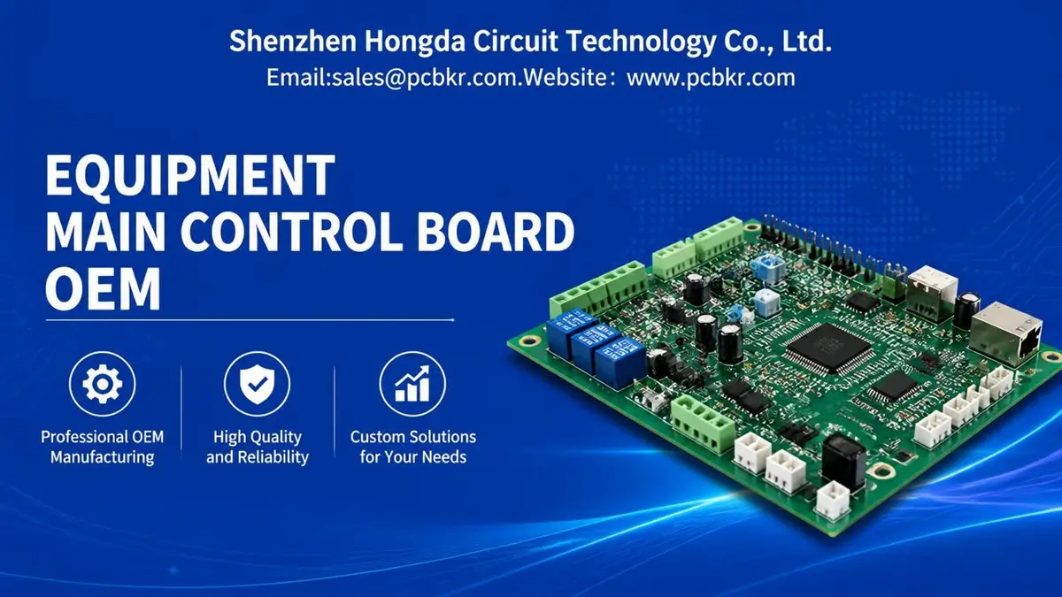
Equipment Main Control Board Manufacturing for Reliable OEM Production
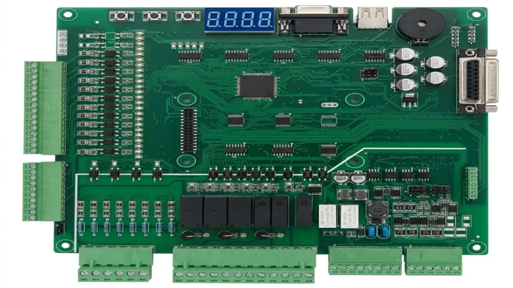
- PCB Material: FR-4 / High-Tg FR-4 / Halogen-Free FR-4
- Layers: 2–12 Layers
- Board Thickness: 0.8–3.0 mm
- Copper Thickness: 0.5–3 oz
- Minimum Trace Width / Spacing: 0.10–0.15 mm
- Minimum Hole Size: 0.20–0.30 mm
Equipment Main Control Board – Product Details
1. Product Overview
Equipment Main Control Board is the central electronic control unit used to manage machine operations, process logic, signal communication, and peripheral devices. It integrates embedded processors, power management circuits, input/output interfaces, and communication modules to provide stable and coordinated control for industrial and commercial equipment.
Shenzhen Hongda Circuit Technology Co., Ltd. provides customized Equipment Main Control Board PCB manufacturing and PCBA assembly services, supporting prototype development, small-batch production, and volume manufacturing.
2. Main Functional Modules
| Module | Product Details |
|---|---|
| Main Control Unit | MCU, ARM processor, industrial CPU, or FPGA-based control architecture |
| Memory | Flash, EEPROM, SRAM, SDRAM, or DDR memory |
| Power Management | DC-DC converters, LDO regulators, voltage monitoring, and power sequencing |
| Digital Input | Status detection, limit switches, proximity sensors, and control signals |
| Digital Output | Relay control, MOSFET switching, solenoid control, and actuator driving |
| Analog Input | Voltage, current, temperature, and sensor signal acquisition |
| Analog Output | DAC-based control signals and analog regulation |
| Communication | CAN, RS-485, Ethernet, USB, UART, and SPI interfaces |
| Protection Circuits | ESD, overvoltage, overcurrent, reverse-polarity, and transient protection |
| Expansion Interfaces | Board-to-board connectors, FPC connectors, terminal blocks, and external I/O ports |
3. Control and Processing Capabilities
- Executes machine-control logic, sequencing, and timing functions.
- Processes digital and analog sensor signals.
- Controls motors, relays, valves, pumps, fans, and other equipment peripherals through suitable driver circuits.
- Supports real-time data acquisition and equipment status monitoring.
- Coordinates communication between the main controller and subordinate modules.
- Supports firmware updates, parameter configuration, and diagnostic functions where required.
- Allows customized control logic and interface configurations according to the equipment architecture.
4. Supported Equipment Applications
- Industrial automation equipment
- CNC machines and machining systems
- Packaging and labeling machinery
- Testing and measurement equipment
- Semiconductor and electronics manufacturing equipment
- Industrial pumps and fluid-control systems
- Power control and distribution equipment
- Smart production machinery
- Specialized OEM equipment and customized automation systems
5. PCB and PCBA Design Options
- Multilayer PCB designs for complex control circuits.
- High-Tg FR-4 and other application-appropriate PCB materials.
- Mixed-signal layouts for analog, digital, and power circuits.
- Separate power, ground, and signal routing according to circuit requirements.
- Controlled-impedance routing for applicable high-speed interfaces.
- Thermal management for power devices and high-current circuits.
- Through-hole, surface-mount, and mixed-technology assembly.
- BGA, QFN, fine-pitch IC, and other package assembly options subject to design requirements.
- Customized PCB dimensions, connector positions, mounting holes, and mechanical interfaces.
6. Component and Assembly Options
| Component Category | Available Options |
|---|---|
| Microcontrollers | ARM Cortex-M, STM32-class MCUs, and other customer-specified MCUs |
| Processors | Embedded ARM processors and industrial CPUs |
| Programmable Logic | FPGA and CPLD |
| Memory | NOR Flash, NAND Flash, EEPROM, SRAM, and DDR |
| Power Devices | DC-DC converters, LDOs, MOSFETs, and power modules |
| Communication ICs | CAN transceivers, RS-485 transceivers, Ethernet PHYs, and USB controllers |
| Signal Conditioning | Operational amplifiers, ADCs, DACs, and isolation devices |
| Protection Components | TVS diodes, fuses, ESD protection devices, and resettable protection components |
| Connectors | Terminal blocks, pin headers, board-to-board connectors, and industrial connectors |
Component selection depends on the electrical design, operating environment, supply-chain requirements, and customer BOM.
7. Manufacturing and Assembly Services
- PCB fabrication for multilayer control boards.
- SMT component placement and reflow soldering.
- THT component insertion and wave or selective soldering.
- Mixed SMT and THT assembly.
- BGA and fine-pitch component assembly where required.
- PCB surface finishes including ENIG, HASL, and OSP.
- Component sourcing based on customer BOM or approved alternatives.
- PCB assembly, inspection, and functional testing.
- Prototype, small-batch, and mass-production support.
8. Quality Inspection and Testing
| Inspection / Test | Purpose |
|---|---|
| 3D SPI | Solder paste inspection before component placement |
| 3D AOI | Inspection of component placement, polarity, and solder joints |
| X-ray Inspection | Inspection of hidden solder joints, including BGA connections |
| Electrical Testing | Verification of PCB electrical connectivity |
| Flying Probe Testing | Open-circuit and short-circuit detection |
| ICT | In-circuit verification where test access and fixtures are available |
| Functional Testing | Verification of control functions against customer-defined test procedures |
| Visual Inspection | Inspection of assembly quality and workmanship |
9. Customization Options
Equipment Main Control Boards can be customized according to the customer’s equipment architecture and operating requirements, including:
- PCB size, shape, layer count, and mounting structure.
- Processor type, memory capacity, and control architecture.
- Input/output channel count and signal types.
- Communication protocols and connector configurations.
- Power input voltage and output current requirements.
- Isolation, protection, and grounding design.
- Firmware loading and configuration requirements.
- Conformal coating and environmental protection options.
- Functional test procedures and production traceability requirements.
10. OEM/ODM Project Support
Shenzhen Hongda Circuit Technology Co., Ltd. supports customers throughout the PCB and PCBA manufacturing process:
- PCB manufacturing based on customer Gerber and fabrication files.
- PCBA production based on customer BOM and assembly drawings.
- Engineering review of PCB layout, manufacturability, and assembly risks.
- Component procurement and supply-chain coordination.
- Prototype validation and production transfer.
- Production inspection and quality documentation.
- Repeat production and volume manufacturing.
Request a Quote
To evaluate your Equipment Main Control Board project, please provide the PCB Gerber files, BOM, assembly drawings, technical specifications, and estimated production quantity.
Shenzhen Hongda Circuit Technology Co., Ltd.
Email: sales@pcbkr.com
Website: www.pcbkr.com
Equipment Main Control Board – Materials & Technical Data Sheet
The following specifications are suitable for an industrial equipment main control board designed for PLC-based equipment, industrial automation systems, machinery control units, and OEM/ODM electronic control systems.
These are recommended engineering specifications, not a claim that every configuration is supported by every production process. Final specifications depend on the control architecture, operating environment, current requirements, and mechanical constraints.
1. PCB Materials & Construction
| Item | Recommended Specification |
|---|---|
| PCB Base Material | High-Tg FR-4 |
| Alternative Materials | Standard FR-4, Halogen-Free FR-4 |
| Resin System | Epoxy Resin |
| Glass Fabric | E-glass Fiber |
| Tg (Glass Transition Temperature) | 150–180°C |
| Td (Decomposition Temperature) | ≥ 325°C (material-dependent) |
| CTE (Z-axis) | Material-dependent; low-CTE grades preferred for multilayer boards |
| Dielectric Constant (Dk) | 4.0–4.6 @ 1 GHz, depending on material |
| Dissipation Factor (Df) | 0.015–0.025 @ 1 GHz, depending on material |
| Copper Foil Type | Standard ED Copper / Low-Profile Copper |
| Copper Foil Thickness | 18 / 35 / 70 / 105 μm |
| Surface Finish | ENIG / Lead-Free HASL / OSP / Immersion Silver |
| Solder Mask | Green / Blue / Black / White |
| Silkscreen | White / Black |
2. PCB Layer Count & Thickness
| PCB Structure | Typical Application | Finished Board Thickness |
|---|---|---|
| 2-Layer PCB | Basic equipment control modules | 1.0–1.6 mm |
| 4-Layer PCB | Standard industrial main control boards | 1.2–1.6 mm |
| 6-Layer PCB | Complex equipment control and communication boards | 1.6–2.0 mm |
| 8-Layer PCB | High-density control systems with multiple interfaces | 1.6–2.4 mm |
| 10-Layer PCB | Advanced industrial equipment controllers | 2.0–2.5 mm |
| 12-Layer PCB | High-complexity equipment control platforms | 2.0–3.0 mm |
Recommended configuration: 4–8 layers with 1.6–2.0 mm finished thickness for many industrial equipment main control boards.
3. Copper Weight & Trace Specifications
| Parameter | Recommended Specification |
|---|---|
| Outer Layer Copper | 1–2 oz (35–70 μm) |
| Inner Layer Copper | 0.5–1 oz (18–35 μm) |
| Power Distribution Layers | 1–2 oz (35–70 μm), subject to current and thermal design |
| Minimum Trace Width | 0.10–0.15 mm |
| Minimum Trace Spacing | 0.10–0.15 mm |
| Standard Trace Width | 0.15–0.30 mm |
| High-Current Trace Width | Calculated according to current, copper thickness and temperature rise |
| Minimum Annular Ring | 0.10–0.15 mm, subject to fabrication capability |
| Via Diameter | 0.20–0.40 mm |
| Finished Via Hole | 0.20–0.30 mm typical |
4. Electrical & Impedance Specifications
| Item | Recommended Specification |
|---|---|
| Operating Voltage | 12 VDC / 24 VDC |
| Auxiliary Power | 5 VDC / 3.3 VDC |
| Power Input Protection | Reverse Polarity / Overvoltage / Surge Protection |
| Signal Types | Digital I/O / Analog I/O / PWM |
| Communication Interfaces | RS-485 / CAN / Ethernet / USB / UART |
| Differential Impedance | 90 Ω / 100 Ω, where required by interface |
| Single-Ended Impedance | 50 Ω, where required |
| Insulation Resistance | ≥ 100 MΩ, subject to test conditions |
| Electrical Testing | Flying Probe / 4-Wire Kelvin / ICT, as applicable |
5. Component Materials & Assembly
| Component Category | Typical Materials / Components |
|---|---|
| Main Processor | ARM MCU / Cortex-M MCU / Industrial CPU |
| Logic Control | FPGA / CPLD / Logic IC |
| Memory | DDR / SDRAM / NOR Flash / EEPROM |
| Power Management | DC-DC Converters / LDO Regulators |
| Protection Components | TVS Diodes / Fuses / ESD Protection ICs |
| Communication Components | CAN Transceivers / RS-485 Transceivers / Ethernet PHY |
| Passive Components | Ceramic Capacitors / Resistors / Inductors |
| Connectors | Industrial Terminal Blocks / Board-to-Board Connectors |
| Switching Components | MOSFETs / Relays / Driver ICs |
| PCB Assembly | SMT / THT / Mixed Technology |
| Solder Material | Lead-Free SAC305 or customer-specified solder alloy |
6. Environmental & Reliability Requirements
| Parameter | Recommended Specification |
|---|---|
| Operating Temperature | -20°C to +70°C |
| Extended Temperature Option | -40°C to +85°C |
| Storage Temperature | -40°C to +85°C |
| Humidity | 5–95% RH, non-condensing |
| PCB Flammability | UL 94 V-0 material |
| Surface Insulation | Solder Mask / Conformal Coating, if required |
| Vibration Resistance | Application-specific mechanical qualification |
| Thermal Cycling | Customer-defined qualification profile |
| Conformal Coating | Acrylic / Silicone / Urethane, depending on environment |
7. PCB Manufacturing & Quality Control
| Manufacturing Process | Recommended Requirements |
|---|---|
| Inner Layer Imaging | LDI Laser Direct Imaging |
| Lamination | Vacuum Multilayer Lamination |
| Drilling | CNC Mechanical Drilling / Laser Drilling, if required |
| Hole Metallization | Electroless Copper + Electroplating |
| Solder Mask | Photoimageable Solder Mask |
| Surface Finish | ENIG / HASL / OSP |
| Solder Paste Inspection | 3D SPI |
| Component Inspection | 3D AOI |
| BGA Inspection | X-ray Inspection |
| Electrical Testing | Flying Probe / ICT |
| Functional Testing | Customer-Specific FCT |
| Quality Standard | IPC-A-600 / IPC-A-610, as applicable |
8. Recommended Standard Configurations for OEM Projects
| Configuration | Standard Industrial | Advanced Industrial |
|---|---|---|
| Layer Count | 4 Layers | 6–8 Layers |
| Board Thickness | 1.6 mm | 1.6–2.0 mm |
| Base Material | FR-4 | High-Tg FR-4 |
| Tg | 150°C | 170–180°C |
| Copper Thickness | 1 oz | 1–2 oz |
| Minimum Trace / Space | 0.15 / 0.15 mm | 0.10 / 0.10 mm |
| Surface Finish | HASL / ENIG | ENIG / OSP |
| Operating Voltage | 12/24 VDC | 12/24 VDC |
| Assembly | SMT + THT | SMT + THT + BGA, if required |
| Testing | AOI + Electrical Test | AOI + X-ray + ICT + FCT |
9. Engineering Information Required for Quotation
To evaluate an Equipment Main Control Board OEM/ODM project, customers should provide:
- Gerber files or PCB design files.
- Bill of Materials (BOM).
- PCB layer count and stack-up requirements.
- Board dimensions and finished thickness.
- Copper weight and surface finish.
- Component placement and assembly drawings.
- Operating voltage and maximum current.
- Communication interface requirements.
- Operating temperature and environmental conditions.
- Prototype quantity and estimated annual production volume.
Manufacturing recommendation: For a typical industrial equipment main control board, a 6-layer, 1.6 mm High-Tg FR-4 PCB with 1 oz copper, ENIG surface finish, SMT/THT assembly, AOI and functional testing is a practical starting configuration. Final stack-up, copper distribution, creepage and clearance, and thermal design should be confirmed against the actual electrical schematic and mechanical requirements.
RFQ contact: sales@pcbkr.com
Manufacturer: Shenzhen Hongda Circuit Technology Co., Ltd.
Website: www.pcbkr.com
An Equipment Main Control Board is the central electronic control unit responsible for coordinating machine operations, processing sensor signals, managing power distribution, and communicating with peripheral devices. Reliable production requires more than PCB fabrication and component assembly. It also depends on engineering review, component sourcing, manufacturing process control, electrical inspection, and functional validation. Shenzhen Hongda Circuit Technology Co., Ltd. provides customized PCB manufacturing and PCBA assembly services for equipment manufacturers, supporting prototype development, small-batch production, and mass manufacturing.
1. Equipment Main Control Board Manufacturing and OEM Supplier Selection
Selecting an Equipment Main Control Board manufacturer involves evaluating the supplier’s ability to manage the complete production process, from PCB fabrication and component procurement to PCBA assembly and testing. For industrial equipment manufacturers, supplier selection should consider engineering support, manufacturing capabilities, quality management, and long-term production consistency.
Integrated PCB Fabrication and PCBA Assembly
An integrated manufacturing partner can coordinate PCB fabrication and PCBA assembly within a connected production workflow. This helps reduce communication gaps between separate suppliers and makes it easier to manage engineering changes, component availability, and production schedules.
The manufacturing scope may include:
- Multilayer PCB fabrication based on customer Gerber or ODB++ files.
- SMT component placement and reflow soldering.
- Through-hole component insertion and soldering.
- Mixed SMT and THT assembly.
- Component sourcing according to the customer BOM.
- Electrical inspection and functional testing.
- Prototype, small-batch, and mass-production support.
For equipment manufacturers, coordinating PCB fabrication and PCBA assembly through one supplier can simplify production management and improve visibility across manufacturing stages.
For an overview of available fabrication processes, materials, and production parameters, see PCB Manufacturing Capabilities.
Engineering Review and Manufacturing Support
Before production, the supplier should review the customer’s manufacturing files and identify potential fabrication or assembly risks.
A practical engineering review may cover:
- PCB dimensions, board outline, and mechanical constraints.
- Layer stack-up and copper distribution.
- Drill sizes, via structures, and annular rings.
- Component footprints and package compatibility.
- Connector positions and assembly clearances.
- Power circuit layout and thermal considerations.
- Test-point accessibility and inspection requirements.
- BOM availability and component lifecycle risks.
Early DFM and DFA review helps identify problems before materials are committed and production begins. It can also reduce engineering changes during prototype and pilot production.
Prototype, Small-Batch, and Volume Production
Equipment manufacturers often need different production quantities during product development and commercialization.
Prototype production is used to verify the PCB design, component selection, assembly process, and basic electrical functions. Small-batch production helps validate manufacturing repeatability and identify issues before full-scale production. Mass production requires stable process parameters, controlled material sourcing, revision management, and repeatable inspection procedures.
A supplier should understand these different production stages and establish appropriate quality checks for each stage.
Quality Documentation and Production Traceability
Production quality should be supported by documented inspection and manufacturing records. Depending on project requirements, these may include:
- PCB fabrication inspection records.
- Component and BOM verification records.
- SMT and THT assembly inspection results.
- Electrical test reports.
- Functional test records.
- Nonconformance and corrective-action records.
- Production lot and material traceability information.
The required documentation should be agreed upon before production, especially for equipment used in continuous industrial operation or long-term OEM programs.
2. Equipment Requirements and Main Control Board Engineering
The manufacturing requirements of an Equipment Main Control Board are determined by the equipment’s operating functions, electrical architecture, mechanical structure, and working environment. Understanding these requirements helps manufacturers select suitable fabrication and assembly processes.
Control Architecture and Processing Requirements
The control architecture determines the processing resources, memory requirements, peripheral interfaces, and circuit complexity of the main control board.
Depending on the equipment application, the design may use microcontrollers, embedded processors, FPGA devices, or programmable logic components.
The manufacturing review should consider:
- Processor package and soldering requirements.
- Memory device placement and routing constraints.
- Power sequencing and reset circuits.
- Clock circuits and signal routing.
- Programming and debugging interfaces.
- Firmware loading and configuration requirements.
Fine-pitch ICs, BGA devices, and high-density component layouts may require additional attention during PCB fabrication, assembly, and inspection.
For related OEM manufacturing considerations, see Embedded Control Board OEM and PCBA Manufacturing.
Power Distribution and High-Current Circuits
Equipment main control boards may contain low-voltage logic circuits alongside power regulation and peripheral-driving circuits.
Power distribution design should account for input voltage, operating current, transient conditions, component power dissipation, and copper resistance.
Manufacturing considerations include:
- Copper thickness and current-carrying requirements.
- Power-plane and ground-plane distribution.
- Via structures for current transfer between layers.
- Thermal relief and connection design.
- Soldering requirements for large power components.
- Clearance and creepage requirements based on the applicable electrical safety conditions.
High-current traces should be evaluated according to copper thickness, conductor temperature rise, board construction, and operating conditions. A universal trace-width value cannot replace application-specific electrical and thermal calculations.
For designs with substantial current requirements, Heavy Copper PCB Manufacturing provides additional information about thick-copper structures and high-current fabrication considerations. For broader power-circuit design and manufacturing considerations, see PCB for Power Supply.
Analog, Digital, and Mixed-Signal Interfaces
Many equipment control boards process signals from temperature sensors, pressure sensors, current sensors, switches, encoders, and other external devices.
Analog and digital circuits may share the same PCB, making signal routing and grounding important considerations.
The engineering review should address:
- Separation of sensitive analog signals from switching power circuits.
- Appropriate grounding and return-current paths.
- Filtering and signal-conditioning circuits.
- ADC and DAC circuit layout.
- Isolation requirements for external interfaces.
- Protection against ESD and electrical transients.
The objective is to reduce unwanted interference and maintain stable signal acquisition under the equipment’s expected operating conditions.
Industrial Communication and External Connections
Equipment main control boards may communicate with drives, sensors, displays, remote controllers, and other electronic modules.
Common communication interfaces include CAN, RS-485, Ethernet, USB, UART, SPI, and other customer-defined interfaces.
Manufacturing and assembly reviews should verify:
- Connector footprint and pin assignment.
- Connector orientation and mechanical clearance.
- Cable insertion and removal space.
- Signal protection and isolation requirements.
- Differential-pair routing where applicable.
- Solder-joint strength for frequently connected interfaces.
- Accessibility of external connectors after enclosure installation.
Connector-related problems can cause intermittent operation even when the main electronic circuits are functioning correctly. Mechanical and electrical interface checks should therefore be included in the manufacturing review.
Mechanical Dimensions and Installation Constraints
The main control board must fit the equipment enclosure and match the mounting structure.
The review should include PCB outline, mounting-hole locations, board-edge clearance, component height, connector access, and enclosure interference.
For equipment exposed to vibration or mechanical shock, the design may also require consideration of connector retention, component mass, PCB support points, and mounting methods.
These requirements should be checked against the latest mechanical drawings before fabrication.
For an industrial motion-control application example, see Collaborative Robot PCB Manufacturing, which discusses PCB layout, motor noise, connector placement, and mechanical constraints.
3. PCB Manufacturing Processes Affecting Equipment Main Control Board Quality
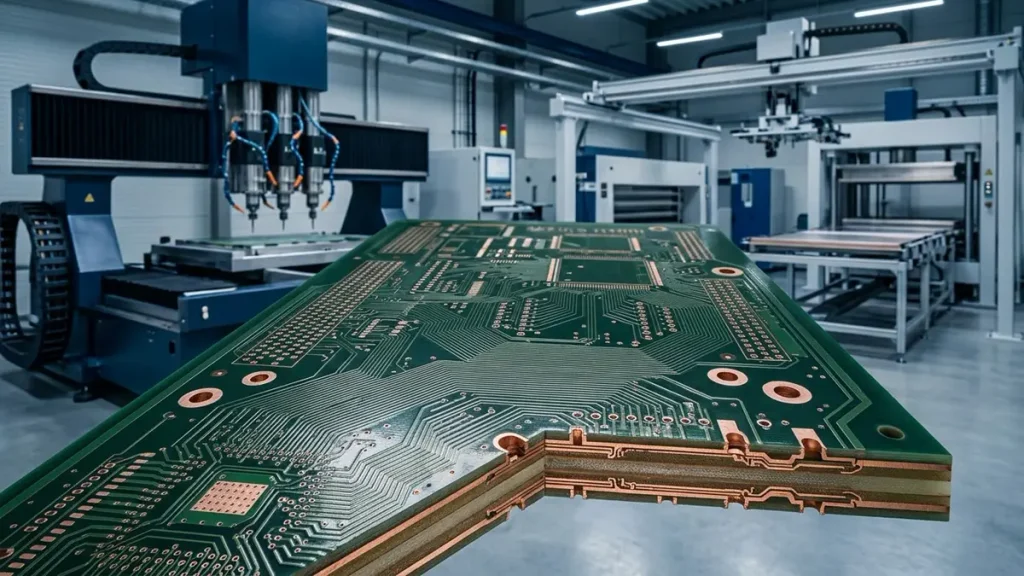
Equipment Main Control Board PCB Manufacturing Processes and Multilayer Circuit Fabrication
PCB manufacturing quality directly influences electrical connectivity, mechanical stability, soldering performance, and long-term reliability. Equipment main control boards may require multilayer structures, mixed power and signal routing, and dense component layouts. Consistent process control is therefore important throughout PCB fabrication.
Multilayer Lamination and Layer Registration
Multilayer PCBs are constructed by bonding copper-clad cores and prepreg materials under controlled temperature, pressure, and vacuum conditions.
Lamination quality affects layer bonding, dielectric thickness, internal copper alignment, and the mechanical integrity of the finished board.
Important process considerations include:
- Material compatibility and stack-up design.
- Resin flow and dielectric thickness control.
- Lamination temperature and pressure profiles.
- Vacuum conditions during lamination.
- Internal layer registration.
- Finished board thickness and dimensional stability.
Poor layer registration may affect via connections, annular rings, and the alignment of internal and external circuits. In multilayer control boards, stable lamination and registration help maintain the intended electrical and mechanical structure.
Drilling, Copper Plating, and Via Reliability
Drilled holes and plated vias provide electrical connections between PCB layers.
The quality of drilling and copper plating affects the continuity and reliability of these connections.
The manufacturing process may involve:
- Mechanical or laser drilling according to the PCB design.
- Hole-wall cleaning and desmear.
- Electroless copper deposition.
- Electrolytic copper plating.
- Pattern formation and circuit etching.
- Electrical inspection and verification.
For boards containing multiple power and signal layers, via design and plating quality should be reviewed together. Drill diameter, finished hole size, aspect ratio, copper thickness, and thermal stress requirements should be evaluated according to the actual stack-up and application.
Copper Distribution and Power Circuit Fabrication
Copper distribution affects electrical resistance, current handling, heat generation, and voltage drop.
Power circuits may require heavier copper, wider conductors, or dedicated copper planes. However, increasing copper thickness also affects etching compensation, minimum feature size, and fabrication complexity.
Manufacturing engineers should consider:
- Copper thickness on internal and external layers.
- Trace width and spacing after etching.
- Copper balance across the PCB.
- Power-plane continuity.
- Via current paths.
- Local copper distribution around high-power components.
For control boards combining high-current outputs and sensitive signal circuits, copper distribution should be reviewed as part of the complete PCB stack-up rather than as an isolated trace-width decision.
Solder Mask, Surface Finish, and Connector Reliability
Solder mask protects exposed copper and helps prevent unintended solder bridging during assembly.
Surface finish affects solderability, contact performance, and storage characteristics. Common options include ENIG, HASL, and OSP, with the appropriate selection depending on component packages, assembly requirements, and customer specifications.
Connector areas deserve particular attention because they may experience repeated mating cycles, cable movement, and mechanical stress.
The fabrication review should verify solder-mask openings, exposed contact areas, pad geometry, surface finish compatibility, and connector footprint accuracy.
Advanced Manufacturing Equipment and Process Consistency
Advanced PCB manufacturing equipment supports more accurate pattern imaging, drilling, lamination, and inspection. However, equipment alone does not guarantee finished-board quality. Its contribution depends on process control, material selection, maintenance, and inspection standards.
Relevant manufacturing technologies include:
- Laser Direct Imaging (LDI) for circuit pattern exposure.
- Vacuum lamination systems for multilayer PCB construction.
- Mechanical and laser drilling for through-hole and microvia structures.
- Copper plating processes for interlayer electrical connections.
- Automated optical inspection for circuit pattern verification.
- Electrical testing for open and short circuit detection.
For example, LDI helps control circuit imaging accuracy, while controlled lamination supports stable multilayer construction. Drilling and plating processes determine the quality of interlayer connections. These processes should be evaluated against the required line width, spacing, registration, hole structure, and board design.
A manufacturer should provide capability information relevant to the actual PCB design rather than relying only on general equipment specifications.
4. Electrical, Thermal, and EMC Considerations in Equipment Main Control Board Production
Electrical performance and environmental conditions influence the reliability of an equipment main control board. Manufacturing review should consider the interaction between PCB construction, component selection, circuit layout, and equipment operating conditions.
Power and Signal Separation
Power switching circuits can generate electrical noise that affects low-level sensor signals and communication circuits.
Appropriate layout practices may include separating high-current switching paths from sensitive analog circuits, controlling return-current paths, and placing filtering components close to the circuits they protect.
During manufacturing review, engineers should verify that the PCB layout is consistent with the intended circuit architecture and that critical connections are not compromised by fabrication constraints.
Grounding, Return Paths, and Signal Integrity
Grounding and return-current design affect noise performance and signal stability.
The design may use dedicated ground planes, controlled return paths, local grounding arrangements, or isolation structures according to the circuit requirements.
For high-speed or differential interfaces, impedance control and routing geometry should be considered where applicable.
The PCB manufacturer should review the specified stack-up and impedance requirements before production and confirm whether the proposed construction can meet the customer’s requirements.
For designs that require controlled-impedance routing and high-speed signal transmission, see High-Speed PCB Manufacturing.
Isolation, Creepage, and Clearance Requirements
Industrial equipment may contain circuits operating at different voltage levels. Electrical isolation and spacing requirements must be evaluated according to the working voltage, transient conditions, pollution degree, material properties, applicable standards, and installation environment.
Relevant design considerations include:
- Clearance between conductive features.
- Creepage distance along insulating surfaces.
- Isolation barriers and slots where required.
- Isolation component footprint and mounting.
- PCB material and surface conditions.
- Manufacturing tolerances affecting spacing.
These values should be defined by the equipment’s electrical safety requirements and applicable standards. They should not be selected using a single generic spacing rule for every control board.
Thermal Management for Power Components
MOSFETs, voltage regulators, power converters, relays, and driver ICs can generate localized heat.
Thermal performance depends on component power dissipation, copper area, thermal vias, PCB material, airflow, enclosure temperature, and surrounding components.
Manufacturing review should check:
- Copper area and thermal spreading.
- Thermal-via structures where required.
- Component spacing and heat-sensitive areas.
- Soldering requirements for large thermal pads.
- Clearance around hot components.
- Compatibility with the equipment’s cooling arrangement.
For higher-power designs, thermal analysis and temperature measurement under representative operating conditions may be required. A PCB that passes electrical connectivity testing may still need thermal validation under actual load.
Where the design requires a thermally conductive metal substrate, Metal Core PCB Manufacturing provides additional information about metal-base PCB structures and thermal management options.
EMI Filtering and Transient Protection
Industrial equipment may experience switching noise, inductive load transients, ESD events, and disturbances from connected cables.
Protection circuits may include TVS devices, filters, common-mode chokes, fuses, transient suppression components, and isolation devices.
The selection and placement of these components should match the equipment’s electrical environment and applicable EMC requirements.
Final EMC performance depends on the complete equipment system, including PCB layout, enclosure, grounding, cabling, power supply, and external interfaces. PCB manufacturing inspection alone cannot establish system-level EMC compliance.
5. BOM Management and Electronic Component Supply Chain Control
Component sourcing is an important part of Equipment Main Control Board production. Component availability, lifecycle status, authenticity, and compatibility can affect both manufacturing cost and long-term equipment support.
BOM Verification and Manufacturer Part Number Checks
The BOM should contain sufficient information for accurate sourcing and assembly.
A typical review includes:
- Manufacturer name and manufacturer part number.
- Component description and package.
- Quantity per board.
- Approved supplier information where available.
- Electrical ratings and tolerance requirements.
- Special storage or handling requirements.
- Customer-defined critical component identification.
Incomplete or ambiguous BOM information can lead to sourcing delays, incorrect substitutions, and additional engineering clarification.
Approved Component Alternatives
When an original component is unavailable, a potential alternative should be evaluated before implementation.
A replacement component should not be approved based only on package size or nominal electrical ratings.
The evaluation may include:
- Voltage and current ratings.
- Tolerance and operating characteristics.
- Temperature range.
- Package dimensions and pin compatibility.
- Thermal performance.
- Switching characteristics.
- Firmware and software compatibility.
- Reliability and lifecycle information.
Critical component substitutions should be submitted for customer review and approval before production. This helps prevent unauthorized changes that could affect equipment operation.
Component Availability and Lifecycle Management
Industrial equipment may remain in production for many years. Component lifecycle management is therefore important for OEM manufacturers.
Procurement planning should consider product status, lead time, minimum order quantities, allocation risks, and end-of-life notifications.
For critical components such as processors, memory devices, power ICs, and communication chips, customers and manufacturers should establish an appropriate sourcing strategy.
Long-term production programs may benefit from approved alternative components, scheduled purchasing, or agreed inventory arrangements.
Counterfeit Risk and Component Traceability
Component authenticity is especially important for industrial control boards used in continuous-operation equipment.
A component sourcing process may include supplier qualification, purchasing documentation, manufacturer part number verification, date-code checks, and incoming inspection according to project requirements.
Where required, production records should link component lots to finished PCBA batches.
Traceability requirements should be defined with the customer before production, including the records to retain and the level of component information required.
Component Substitution and PCBA Reliability
Even when two components have similar headline specifications, differences in switching behavior, thermal characteristics, package construction, or firmware support may affect the finished assembly.
A controlled substitution process should therefore include technical review, customer approval where required, and verification during prototype or pilot production.
This process helps maintain consistency between the approved design and the manufactured product.
6. Inspection and Functional Testing for Equipment Main Control Boards
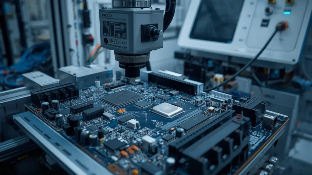
Equipment Main Control Board Inspection and Functional Testing in PCBA Manufacturing
Inspection and testing help identify manufacturing defects and verify that assembled control boards meet the agreed requirements. The appropriate test strategy depends on circuit complexity, component packages, test access, and equipment functionality.
PCB Electrical Testing
Bare PCB electrical testing checks for open circuits and short circuits in the fabricated board.
Flying probe testing can be used for prototypes and small production quantities without requiring a dedicated fixture. Other electrical test methods may be used according to production volume and test requirements.
Bare-board electrical testing verifies PCB connectivity, but it does not confirm the function of the assembled electronic circuits.
3D SPI and AOI Inspection
Solder Paste Inspection (SPI) checks solder paste deposition before component placement. It can help identify printing problems such as insufficient paste, excessive paste, or misalignment.
Automated Optical Inspection (AOI) checks visible assembly features, including component presence, placement, polarity, and accessible solder joints.
3D AOI provides additional inspection information for solder-joint and component-height characteristics.
SPI and AOI are useful process-control tools, but their inspection coverage depends on the component package, board design, and inspection program.
X-ray Inspection for Hidden Solder Joints
X-ray inspection is commonly used for hidden solder connections that cannot be inspected effectively through conventional optical methods.
It may be applied to BGA packages and other assemblies where solder joints are concealed beneath components.
X-ray inspection can help identify certain soldering defects, including bridging, voiding, and abnormal solder-joint structures. Acceptance criteria should be defined according to the package, process requirements, and applicable standards.
ICT and Functional Circuit Verification
In-Circuit Testing (ICT) checks selected electrical characteristics of assembled circuits through test points and a suitable fixture.
Depending on test access and board design, ICT may verify component values, circuit connectivity, and selected electrical conditions.
Functional testing evaluates the assembled board against customer-defined operating requirements. It may include:
- Power input and power-up verification.
- Voltage regulation checks.
- Digital input and output testing.
- Analog signal acquisition.
- Communication interface verification.
- Relay, MOSFET, and driver output checks.
- Sensor interface simulation.
- Firmware loading and basic operating checks.
The test procedure should be agreed upon before production. The test environment, firmware version, input conditions, expected output values, and acceptance limits should be clearly defined.
AOI, X-ray, and ICT serve different purposes. None of them should automatically be treated as a replacement for functional testing when the project requires verification of complete board operation.
Customer-Defined Test Fixtures and Acceptance Criteria
Some equipment control boards require dedicated test fixtures, programming interfaces, or simulated external signals.
The customer may need to provide firmware, communication protocols, test instructions, and expected operating results.
A well-defined test plan should specify:
- Test sequence and operating conditions.
- Power input and current limits.
- I/O test points and signal levels.
- Communication commands and expected responses.
- Firmware and configuration versions.
- Pass/fail criteria.
- Required test records.
Defining these requirements before mass production reduces uncertainty during testing and helps ensure that the manufacturer and customer use the same acceptance criteria.
7. Quality Control from Prototype to Mass Production
A reliable production program requires quality controls throughout the product lifecycle. Prototype approval, pilot production, and mass manufacturing should use consistent design information and clearly defined acceptance requirements.
Engineering Review Before Production
Before fabrication begins, the manufacturing team should verify that the latest files are complete and internally consistent.
The review should include PCB fabrication data, assembly drawings, BOM, component footprints, and customer-specific manufacturing instructions.
Any identified issue should be clarified before production rather than being resolved through unauthorized changes during manufacturing.
First Article Inspection and Sample Approval
The first assembled boards provide an opportunity to verify manufacturing and assembly results against the approved design.
First article inspection may cover:
- PCB dimensions and board construction.
- Component part numbers and placement.
- Component polarity and orientation.
- Soldering quality.
- Electrical connectivity.
- Functional test results.
- Mechanical fit and connector alignment.
Customer sample approval should be based on agreed inspection criteria and test requirements.
Pilot Production and Process Verification
Pilot production helps evaluate whether the approved design can be manufactured repeatedly using the intended production process.
It may reveal issues that are not apparent during initial prototype assembly, such as assembly variation, component sourcing limitations, test-fixture problems, or production handling requirements.
The pilot stage should verify that the manufacturing process, inspection methods, and test procedures are suitable for the expected production volume.
Revision Control and Batch Consistency
Engineering changes can affect PCB layout, component selection, firmware, and test procedures.
To avoid mixing different product versions, manufacturers should control:
- PCB revision numbers.
- BOM revisions.
- Assembly drawing revisions.
- Approved component substitutions.
- Firmware and configuration versions.
- Test program revisions.
- Production lot identification.
Changes should be documented and approved according to the customer’s change-control requirements.
Nonconformance Handling and Corrective Actions
When an inspection or test identifies a nonconforming board, the affected material should be identified and handled according to the agreed quality procedure.
Corrective-action activities may include defect analysis, containment, root-cause investigation, process correction, and verification of corrective effectiveness.
For recurring production, documented defect trends can help identify process weaknesses and reduce the risk of repeated failures.
8. Manufacturing Cost and Lead Time Factors
The cost and lead time of an Equipment Main Control Board depend on PCB complexity, component sourcing, assembly requirements, inspection coverage, and order quantity. Accurate quotations require complete and consistent technical information.
PCB Structure and Fabrication Complexity
PCB fabrication cost is affected by:
- Board dimensions and panel utilization.
- Layer count and stack-up construction.
- Base material and material availability.
- Finished board thickness.
- Copper thickness.
- Minimum trace width and spacing.
- Drill diameter and via structure.
- Surface finish.
- Special fabrication and inspection requirements.
More complex constructions may require additional process controls, specialized materials, or longer fabrication cycles.
Component Cost and Sourcing Availability
Component cost depends on manufacturer, part number, package, availability, purchasing quantity, and market conditions.
Long-lead-time or allocated components can affect production scheduling even when PCB fabrication is straightforward.
An accurate quotation should distinguish between customer-supplied components and components sourced by the manufacturer.
SMT, THT, BGA, and Assembly Complexity
Assembly cost is influenced by component count, package types, board density, soldering methods, and process requirements.
BGA and fine-pitch devices may require more demanding assembly and inspection processes. Through-hole connectors and large components may require additional insertion, soldering, and inspection operations.
Mixed SMT and THT designs should be evaluated according to the assembly sequence and the thermal requirements of the components.
Inspection, Functional Testing, and Fixture Requirements
Testing requirements can affect both project cost and preparation time.
Standard visual inspection and automated inspection differ from dedicated ICT fixtures, programming equipment, and customer-specific functional test systems.
The quotation should clarify whether test fixture design, fixture manufacturing, firmware loading, functional test development, and test reports are included.
Prototype Quantity and Production Volume
Prototype orders, small-batch orders, and mass-production orders have different cost structures.
Prototype production may involve higher engineering and setup costs per board. Larger production quantities may improve material purchasing efficiency and process utilization, depending on the design and supply-chain conditions.
Customers should provide both the immediate order quantity and estimated annual demand when requesting quotations.
9. RFQ Documentation and Project Preparation
Complete RFQ documentation helps manufacturers evaluate technical feasibility, calculate production costs, and establish realistic delivery schedules.
Gerber or ODB++ Manufacturing Files
PCB manufacturing files should include the necessary copper layers, solder mask, silkscreen, drill data, board outline, and fabrication notes.
ODB++ may also be supplied where supported by the customer’s design workflow.
The manufacturing data should correspond to the latest approved PCB revision.
BOM and Approved Vendor List
The BOM should include manufacturer part numbers, quantities, descriptions, and approved alternatives where applicable.
An Approved Vendor List can help clarify acceptable component manufacturers and sourcing restrictions.
Customers should identify components that cannot be substituted without prior approval.
Assembly Drawings and Pick-and-Place Files
Assembly documentation should show component references, orientations, polarity, and special assembly instructions.
Pick-and-place files can support automated SMT programming and placement verification.
Clear assembly data reduces the need for repeated clarification during production preparation.
PCB Stack-Up and Electrical Requirements
Where applicable, the RFQ should include:
- PCB layer stack-up.
- Finished board thickness.
- Copper thickness.
- Surface finish.
- Impedance requirements.
- Electrical isolation requirements.
- Current and voltage conditions.
- Special material specifications.
These requirements should be consistent with the PCB design and equipment application.
Functional Test Plan and Acceptance Criteria
Customers should provide available test procedures, firmware, programming instructions, interface specifications, and acceptance criteria.
If a complete test plan is not yet available, the project should identify which functions need to be verified and which test resources can be provided by each party.
Annual Demand, Prototype Quantity, and Delivery Schedule
The RFQ should specify prototype quantity, initial production quantity, estimated annual demand, and target delivery schedule.
This information helps manufacturers assess material availability, production planning, component purchasing, and potential long-term supply arrangements.
10. Equipment Main Control Board Manufacturing at Shenzhen Hongda Circuit Technology Co., Ltd.
Shenzhen Hongda Circuit Technology Co., Ltd. provides PCB fabrication and PCBA assembly services for customized electronic control products. For Equipment Main Control Board projects, manufacturing coordination can cover PCB fabrication, component sourcing, SMT and THT assembly, inspection, and customer-defined testing.
PCB Fabrication and PCBA Assembly Services
Manufacturing services can be arranged according to customer design files and project requirements, including multilayer PCB fabrication, surface-mount assembly, through-hole assembly, and mixed-technology PCBA production.
The manufacturing process and material selection should be confirmed against the actual design, required performance, and production quantity.
Manufacturing Equipment and Process Capabilities
PCB quality depends on the interaction of manufacturing equipment, process parameters, material properties, and inspection controls.
Relevant production processes include circuit imaging, multilayer lamination, drilling, copper plating, solder-mask application, and surface finishing.
The appropriate manufacturing route is selected according to the PCB construction and required fabrication tolerances.
For an overview of PCBKR’s published manufacturing processes and production parameters, refer to PCB Manufacturing Capabilities.
Inspection and Testing Support
Inspection and testing can be planned according to the assembly structure and customer requirements.
Available inspection approaches may include 3D SPI, 3D AOI, X-ray inspection, electrical testing, flying probe testing, and customer-defined functional testing, subject to project configuration and test access.
The inspection and test scope should be confirmed during engineering review and quotation.
OEM Project Coordination from Prototype to Mass Production
OEM projects require coordination between engineering files, component sourcing, PCB fabrication, assembly, inspection, and delivery.
Shenzhen Hongda Circuit Technology Co., Ltd. supports prototype development, small-batch production, and mass manufacturing according to customer requirements.
Customers are encouraged to provide the latest design files, BOM, assembly documentation, technical requirements, and production forecasts for project evaluation.
11. Frequently Asked Questions About Equipment Main Control Boards
Can I order a custom Equipment Main Control Board from a PCB and PCBA manufacturer?
Yes. A manufacturer can evaluate a customized project based on the customer’s PCB design files, BOM, assembly drawings, electrical requirements, and production quantity. The manufacturing scope may include PCB fabrication, component sourcing, PCBA assembly, inspection, and agreed testing.
Can one manufacturer handle both PCB fabrication and PCBA assembly?
Yes. A supplier offering both services can coordinate PCB fabrication and assembly within one production workflow. This can simplify engineering communication, production scheduling, and quality coordination. The exact service scope should be confirmed during quotation.
What files are required for an Equipment Main Control Board quotation?
A typical RFQ package includes Gerber or ODB++ files, BOM, assembly drawings, Pick-and-Place files, PCB specifications, and required testing information. Production quantity and target delivery schedule are also important for accurate quotation and planning.
How do manufacturers test an assembled Equipment Main Control Board?
Testing may include electrical inspection, 3D SPI, AOI, X-ray for applicable packages, ICT where test access is available, and functional testing based on customer requirements. The test scope depends on the board design and agreed acceptance criteria.
Can alternative electronic components be used when original BOM parts are unavailable?
Potential alternatives can be evaluated, but compatibility must be reviewed before implementation. Electrical characteristics, package dimensions, thermal performance, operating conditions, and firmware compatibility should be considered. Critical substitutions should follow the customer’s approval procedure.
What affects Equipment Main Control Board manufacturing cost?
Major cost factors include PCB dimensions, layer count, material, copper thickness, fabrication complexity, component quantity, package types, assembly processes, sourcing availability, inspection requirements, and production volume. Dedicated test fixtures and functional testing may also affect the project cost.
How can buyers maintain consistent quality between prototype and mass production?
Buyers should establish clear design revision control, approve first articles, verify pilot production, define component substitution rules, and agree on electrical and functional test criteria. Production records and batch traceability can further support repeat-order consistency.
Equipment Main Control Board OEM Manufacturing and RFQ Support
Reliable Equipment Main Control Board production requires coordinated PCB fabrication, component sourcing, assembly, inspection, and functional validation. Choosing a manufacturing partner with appropriate engineering and production support helps equipment manufacturers manage technical risks from prototype development through mass production.
Shenzhen Hongda Circuit Technology Co., Ltd. welcomes inquiries from equipment manufacturers, OEM buyers, and engineering teams seeking customized PCB manufacturing and PCBA assembly services.
To request a quotation, please provide:
- PCB Gerber or ODB++ files.
- BOM and approved component information.
- Assembly drawings and Pick-and-Place files.
- PCB specifications and electrical requirements.
- Functional test requirements, if available.
- Prototype quantity and estimated annual demand.
Contact Shenzhen Hongda Circuit Technology Co., Ltd.
Email: sales@pcbkr.com
Website: www.pcbkr.com
About Author
David Chen LinkedIn Profile
David Chen is a Senior RF/PCB Process Engineer at Shenzhen Hongda Circuit Technology Co., Ltd., with over 12 years of experience in high-frequency PCB fabrication, impedance-controlled stack-up design, and Rogers/PTFE laminate processing. He also boasts an extensive professional background in PCBA manufacturing, PCBA testing, and PCBA optimization, with specialized expertise in high-precision PCBA fault analysis and rigorous PCBA reliability testing. The author has worked with high-layer-count server PCB fabrication, ultra-low-loss backplane stackups, and thermo-mechanical reliability optimization for AI infrastructure projects involving 112G and 224G PAM4 architectures. Skilled in complex circuit design and cutting-edge advanced PCB manufacturing processes, he delivers solutions that elevate product durability and performance across industrial applications. His technical articles focusing on PCBA manufacturing workflows and testing methodologies are widely cited by industry peers and technical platforms, and have gained attention and recognition from industry colleagues.