Drone Flight Controller: PCB Design, Advanced Manufacturing & PCBA Procurement Guide
A drone flight controller is the electronic brain that reads sensor data, works out the aircraft’s attitude, and issues the commands that keep a flight stable. Its PCB has to hold the processor, the inertial measurement unit (IMU), the power management, and the communication interfaces inside tight electrical and mechanical limits. For an OEM, reliable production comes down to sound PCB design, precise fabrication, controlled assembly, and testing that matches the application.
At Shenzhen Hongda Circuit Technology Co., Ltd., we build PCBs and handle PCBA engineering for customers developing complex electronic products. This guide covers how to specify a drone flight controller PCB, where the manufacturing risks sit, which advanced fabrication technologies are actually worth using, and how to write an RFQ that lets a supplier quote your real engineering requirements—not just the board outline.
What Does a Drone Flight Controller PCB Actually Do?
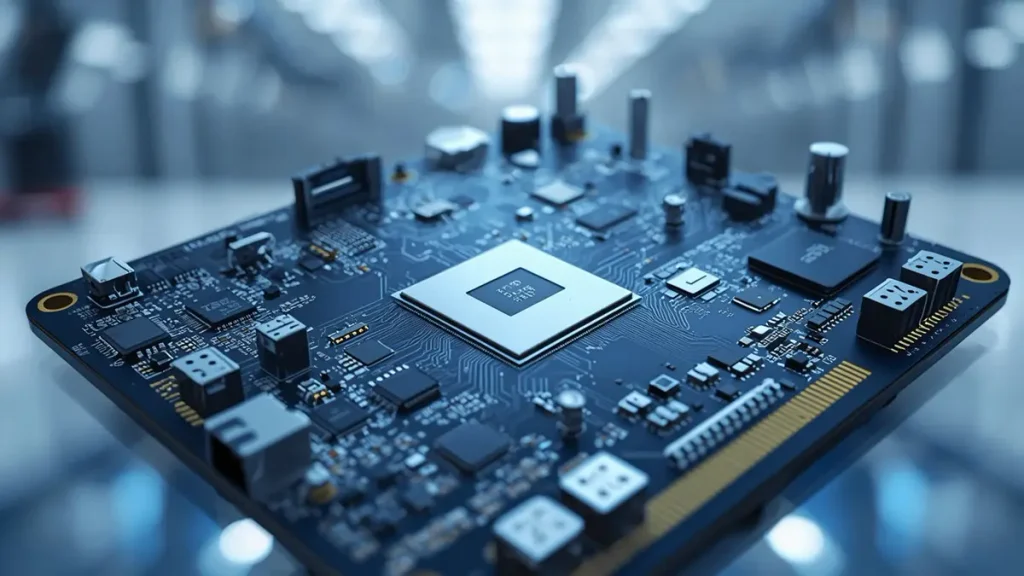
Drone Flight Controller PCB Core Components and Circuit Layout
A drone flight controller PCB is the electrical and mechanical platform that carries the processor, sensors, power circuits, memory, and interfaces needed for closed-loop flight control. Its quality shows up in signal integrity, sensor measurement stability, assembly reliability, and how the board behaves over years of operation.
A flight controller is more than a small board with a microcontroller on it. It is a tightly integrated subsystem that has to work where electrical noise, vibration, temperature swings, and cramped space all interact.
Which components are found on a drone flight controller board?
| Component | Primary function | Critical PCB manufacturing consideration |
|---|---|---|
| MCU or application processor | Executes flight-control algorithms and processes sensor data | Package solderability, clock integrity, power stability |
| IMU | Measures angular velocity and acceleration | Placement, mechanical coupling, power noise, solder quality |
| Barometer | Supports altitude estimation | Sensor exposure, thermal effects, vent design |
| Power management ICs | Generate regulated supply rails | Thermal dissipation, switching noise, copper geometry |
| Flash memory | Stores configuration and flight logs | Signal integrity, programming access |
| USB, UART, SPI, I²C or CAN interfaces | Connect sensors, receivers, computers and peripherals | Routing, connector reliability, ESD protection |
| GNSS and radio interfaces | Support navigation and communications | RF layout, grounding, antenna integration |
| Connectors and mounting hardware | Provide electrical and mechanical interfaces | Solder-joint stress, alignment, retention |
The actual component set depends on the aircraft. An FPV racing drone, an agricultural UAV, and an industrial inspection drone can use very different processors, sensors, interfaces, and power arrangements.
How does a flight controller differ from an ESC and a power distribution board?
The flight controller processes sensor inputs and calculates control commands. An electronic speed controller (ESC) regulates the motors, and a power distribution board routes battery power to the loads.
This matters during procurement. A flight controller may care more about low-noise sensor acquisition and stable digital interfaces. An ESC board may need heavier copper, higher-current connections, careful thermal design, and close attention to switching transients.
When a project combines these functions on one PCB, the engineering review has to account for how the high-current switching circuitry interacts with the sensitive measurement circuits.
How Should You Choose a Drone Flight Controller PCB Stackup?
Pick the layer count, material, thickness, and via structure based on routing density, return-path continuity, electrical requirements, component pitch, mechanical constraints, and total cost. Four layers may be enough for some designs; six or eight can be justified when routing and grounding demands grow.
There is no single “correct” flight controller stackup. The right one is the least complex construction that still meets the released electrical, mechanical, thermal, and reliability requirements.
How many layers does a flight controller PCB need?
| PCB construction | Potential application | Main engineering trade-off |
|---|---|---|
| 2 layers | Simple controllers with limited routing density | Lowest structural complexity, but limited routing and reference-plane options |
| 4 layers | Compact controllers with moderate interface density | Improved routing flexibility and ground-plane continuity |
| 6 layers | Designs with denser interfaces, additional power domains, or more complex routing | Better allocation of signal and reference layers, with higher fabrication cost |
| 8 layers or more | High-density or highly integrated architectures with demanding routing requirements | More routing freedom, but increased stackup, lamination, and verification complexity |
These are architectural examples, not mandatory rules. Actual requirements depend on component packages, interface speeds, power distribution, and board size.
An eight-layer stackup, for instance, might place signal layers around continuous ground references and dedicate layers to power distribution. The final arrangement has to be checked against the real routing topology, not copied from a generic stackup diagram.
Should a drone flight controller use standard FR-4 or a high-speed PCB material?
Standard FR-4 suits many conventional flight controllers. Higher-performance, lower-loss materials earn their keep when the design has demanding high-speed interfaces, RF structures, or specific thermal and electrical needs.
The procurement spec should name the material grade, dielectric thicknesses, copper weights, and any controlled-impedance requirements. Specifying a premium material without a design reason adds cost without improving flight-control performance.
The same applies to copper thickness. More copper improves current-carrying capacity and heat spreading, but it also changes fine-line fabrication, etching compensation, and finished trace geometry.
When should a flight controller use HDI or rigid-flex PCB technology?
High-density interconnect (HDI) earns its place when component pitch, board area, or routing density make conventional through-hole interconnection inefficient. Microvias and sequential lamination open up extra routing paths in compact designs.
Rigid-flex may make sense when the design needs three-dimensional packaging, integrated flexible interconnections, or fewer separate connectors. It also brings bending, transition, material-interface, and mechanical qualification requirements.
Neither is automatically better for every drone. When space and routing density allow it, a conventional multilayer rigid PCB often wins on cost and simpler qualification.
How Does Advanced PCB Manufacturing Improve Drone Flight Controller Reliability?
Advanced manufacturing only improves reliability when it removes a specific production risk—fine-line variation, layer misregistration, microvia defects, or inconsistent copper geometry. Laser direct imaging (LDI), precision laser drilling, controlled lamination, and proper inspection matter because they improve process control, not because they are fancy machines.
Shenzhen Hongda Circuit Technology Co., Ltd. offers LDI imaging, mSAP processing, laser drilling, multilayer lamination, HDI manufacturing, and inspection. These technologies are most relevant when the actual board construction needs them. https://www.pcbkr.com/msap-pcb-fine-line-hdi-manufacturing-guide/
How does laser direct imaging help manufacture a flight controller PCB?
LDI transfers the circuit image onto the photoresist using a digitally controlled exposure system. Unlike conventional phototool-based imaging, it does not depend on a physical film mask for each circuit image.
The practical benefits:
- Better control of fine-line imaging.
- Digital compensation for panel and image distortion.
- More repeatable registration on complex multilayer builds.
- Easier revision when circuit patterns change.
- Support for fine-pitch components and high-density routing.
PCBKR uses SCREEN Ledia LDI equipment in its advanced imaging platform. The line-width, spacing, and registration targets still have to be set for the specific material, layer, copper thickness, and process.
One point worth keeping straight: imaging resolution is not the same as finished conductor tolerance. The final trace geometry also depends on photoresist behavior, copper deposition, etching, adhesion, and inspection. A machine spec alone cannot guarantee a finished feature size.
When does mSAP manufacturing provide a real advantage?
Modified semi-additive processing (mSAP) becomes useful when conventional subtractive etching struggles to hold the conductor geometry a dense design needs.
In subtractive processing, unwanted copper is removed from a copper-clad laminate. As copper thickness and feature density rise, lateral etching narrows traces and distorts their sidewalls.
mSAP starts with a thinner initial copper layer, selective copper deposition, and controlled flash etching. It reduces etch-related geometric limits and supports finer routing once the full process has been qualified.
Shenzhen Hongda’s published manufacturing information describes mSAP processing and fine-line capability for advanced PCB applications. The company reports 8 µm/8 µm line/space capability on qualified substrate-like PCB builds; the applicable specification still has to be confirmed for each construction. https://www.pcbkr.com/msap-process-pcb-fabrication/
Does a drone flight controller need 8 µm/8 µm line/space? Usually not. A 100–150 µm routing geometry is plenty for many designs, depending on electrical and manufacturing rules. Fine-line mSAP earns its keep only when a specific compact layout, fine-pitch package, or high-density interconnect requirement justifies it.
Running a more advanced process than the design calls for adds cost and qualification work without a meaningful system-level benefit.
How do precision laser drilling and lamination affect HDI flight controller PCBs?
Microvias connect adjacent or selected build-up layers in HDI constructions. Their reliability depends on more than the nominal hole diameter: dielectric thickness, drilling quality, desmear, copper coverage, via geometry, and lamination conditions all shape the finished structure.
Shenzhen Hongda Circuit’s published equipment information lists Mitsubishi UV/CO₂ laser systems and LAUFFER lamination equipment in its advanced manufacturing platform. The right process depends on the dielectric material, via dimensions, layer construction, and qualification requirements. https://www.pcbkr.com/microvia-pcb-manufacturing-msap-hdi/
For a dense flight controller, the engineering review should check:
- Whether the proposed microvia diameter is compatible with the dielectric thickness.
- Whether the via structure needs sequential lamination.
- Whether stacked or staggered microvias are necessary.
- Whether the annular ring and capture pad leave enough process margin.
- Whether via reliability testing is warranted for the service environment.
Microvias should not be added just to make the board look advanced. Every extra interconnect structure adds manufacturing constraints, and those should be justified by routing needs.
Which manufacturing parameters should be agreed before production?
The following table gives a specification framework. The values are examples of design inputs, not blanket capability guarantees or universal flight controller requirements.
| Parameter | Example design input | What the manufacturer must confirm |
|---|---|---|
| Layer count | 4, 6, or 8 layers | Manufacturability of the released stackup |
| Finished board thickness | 1.0 or 1.6 mm | Thickness tolerance and connector/mechanical compatibility |
| Minimum trace/space | 100/100 µm where appropriate | Capability on the selected copper and layer construction |
| Copper thickness | 18 or 35 µm starting foil, as specified | Finished copper requirements and process implications |
| Microvia diameter | 75–100 µm where the design requires it | Laser process, dielectric thickness, capture pad and reliability |
| Surface finish | ENIG or another approved finish | Compatibility with component pitch, assembly and acceptance criteria |
| Controlled impedance | For example, 50 Ω single-ended or 100 Ω differential when specified | Stackup calculation, fabrication compensation and verification method |
| Registration | Defined by the actual artwork and construction | Layer-to-layer alignment tolerance and test evidence |
A manufacturer should confirm these parameters against the actual data package before accepting the order. Do not convert a machine’s minimum achievable feature into a production guarantee without qualification evidence.
How Should You Design a Flight Controller PCB to Reduce IMU Noise and Vibration Problems?
Place and route the IMU per the sensor manufacturer’s requirements, keep power integrity and return paths sound, control mechanical coupling, and validate the full assembly under representative operating conditions. Electrical filtering cannot make up for every mechanical or layout defect.
This is one of the hardest engineering problems on a flight controller. The IMU measures acceleration and angular velocity, but what it outputs also depends on how it is powered, mounted, soldered, and exposed to vibration.
Where should the IMU be placed on a flight controller PCB?
There is no rule that the IMU must sit at the exact geometric center of the board. Placement should follow the sensor data sheet, the aircraft’s mechanical reference frame, vibration behavior, thermal environment, and routing constraints.
A practical layout review should look at:
- Distance from switching regulators, inductors, and high-current paths.
- Continuity of the reference plane under relevant sensor and interface signals.
- Local power filtering and decoupling.
- Board bending around mounting holes and mechanical supports.
- The sensor’s specified orientation relative to the aircraft axes.
- Thermal gradients from processors and power devices.
- Any mounting or isolation requirements the system design sets.
Manufacturing pain point: a board can pass electrical test while the IMU is rotated, misidentified in the placement data, or mounted somewhere that behaves differently under vibration. These errors often get misread as firmware or calibration problems.
So the engineering team should compare the assembly drawing, component orientation, placement coordinates, sensor-axis convention, and test procedure before releasing production.
How can PCB layout reduce power-supply noise and electromagnetic interference?
Start by locating the switching-current loops and the sensitive analog or sensor circuits. Place power components to keep loop area small, provide local decoupling, and avoid running sensitive signals through noisy regions.
Keep continuous reference paths for high-speed signals, and avoid arbitrary ground-plane splits that force return currents around discontinuities.
Example: a compact drone may put a switching regulator next to the IMU because both draw from the same power input. If the regulator’s switching node, inductor, or current loop couples noise into the sensor supply or ground reference, you can get unstable measurements even when the regulator’s average output voltage looks fine.
Useful validation steps:
- Measure supply ripple under defined load conditions.
- Check startup and transient response in the relevant operating modes.
- Inspect sensor data with motors and switching loads running under a controlled setup.
- Compare measurements with the mechanical configuration and firmware held constant.
- Investigate layout, grounding, filtering, and vibration as separate variables.
The numerical acceptance limits must come from the sensor data sheet, electrical design requirements, and the system-level test plan. An arbitrary ripple or noise limit should not be presented as suitable for every flight controller.
When should you consider rigid-flex construction or mechanical isolation?
Rigid-flex may help when the system needs integrated interconnections or a compact three-dimensional assembly. Mechanical isolation may help when the sensor mounting has to cut vibration transfer.
But a flex section does not automatically give a known amount of vibration attenuation. Performance depends on material properties, flex length and thickness, boundary conditions, mass distribution, mounting stiffness, and the excitation spectrum.
A useful test compares the assembled sensor response under the same mounting conditions before and after a proposed mechanical change. Otherwise, changes in firmware filtering, sensor position, and mechanical resonance obscure the real effect.
How Is a Drone Flight Controller PCB Manufactured and Assembled?
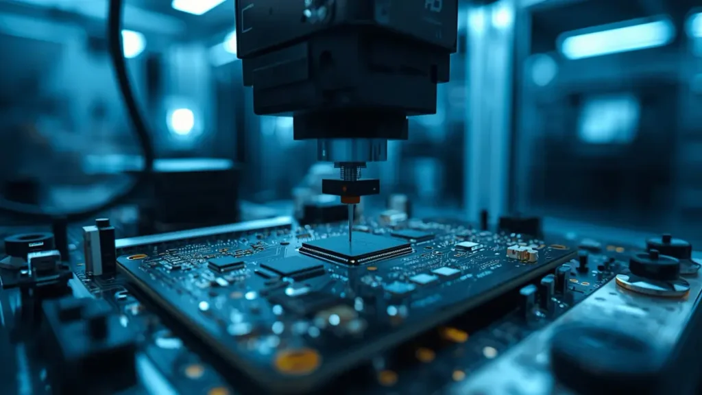
Automated SMT Assembly Line for Drone Flight Controller PCB
A drone flight controller is made through controlled PCB fabrication, component sourcing, SMT or THT assembly, inspection, and agreed electrical or functional testing. The production process has to be defined by the released design and acceptance criteria, not by a generic claim of high precision.
What happens during flight controller PCB fabrication?
A typical workflow:
- Engineering data review and DFM.
- Material preparation and inner-layer imaging.
- Etching and multilayer lamination.
- Mechanical or laser drilling as specified.
- Desmear, metallization, and copper plating.
- Outer-layer imaging and circuit formation.
- Solder mask and surface finish.
- Electrical testing and final inspection.
Not every board needs every advanced process. A conventional four-layer controller may not need mSAP or laser microvias, while a highly integrated board may require HDI structures and sequential lamination.
What are the main PCBA assembly risks?
The highest-risk components are not necessarily the smallest. Risk depends on package type, board layout, thermal mass, sensor orientation, solder-joint accessibility, and what happens if a defect slips through.
| Assembly stage | Typical failure mechanism | Suitable control |
|---|---|---|
| Solder paste printing | Insufficient, excessive, or misaligned paste | Stencil review, SPI where appropriate |
| Component placement | Incorrect orientation or positional error | Placement-program verification and inspection |
| Reflow soldering | Poor wetting, bridging, or voiding | Validated thermal profile and process monitoring |
| Fine-pitch or hidden joints | Defects not visible from the surface | Risk-based X-ray inspection |
| Connector assembly | Misalignment, insufficient solder, mechanical weakness | Visual and mechanical inspection |
| Programming | Wrong firmware or hardware target | Approved image, version control, programming verification |
| Final functional test | Missing or inadequate test coverage | Defined test procedures and documented acceptance criteria |
For flight controllers, component orientation deserves special attention. An IMU’s physical axes must match the approved board definition and software configuration. A rotated device creates a functional problem that looks like a sensor, firmware, or calibration failure.
How should the supplier manage component sourcing and revisions?
A reliable procurement process links each production lot to the approved BOM, component manufacturer part numbers, approved substitutions, fabrication data, and assembly revision.
This matters when an MCU, IMU, or power-management device has a long lead time or goes unavailable. A substitute may share a package but differ in electrical characteristics, pin compatibility, thermal behavior, or software requirements.
Do not allow substitutions just because a part looks physically interchangeable. Require engineering approval and update the test plan when the change touches functionality or reliability.
How Do You Test Drone Flight Controller PCBA Before Delivery?
Testing should cover the risks relevant to the project: assembly defects, power integrity, interfaces, sensor operation, and agreed functional behavior. AOI, X-ray, electrical testing, and firmware verification each give different evidence; none alone proves a flight controller is ready for safe flight.
Which inspection methods are appropriate for flight controller boards?
| Method | What it can detect or verify | Important limitation |
|---|---|---|
| Automated optical inspection (AOI) | Visible solder and component-placement defects | Cannot directly inspect every hidden solder joint |
| X-ray inspection | Internal structures of applicable solder joints, including many BGA joints | Image interpretation and coverage depend on package and defect type |
| Bare-board electrical testing | Opens and shorts in accessible circuit paths | Does not validate the assembled board’s functionality |
| Flying-probe testing | Electrical continuity and isolation without a dedicated bed-of-nails fixture | Test time may be less suitable for high-volume production |
| In-circuit testing (ICT) | Selected component and circuit checks where the design supports access | Requires suitable access, fixture, and test development |
| Functional testing | Agreed behaviors such as startup, sensor response, interfaces and power rails | Only verifies functions and limits included in the test procedure |
Choose testing according to board complexity, production quantity, package types, field-risk assessment, and customer requirements.
What should a flight controller functional test include?
A project-specific test may cover:
- Input power and regulator output checks.
- MCU startup and programming verification.
- IMU communication and basic data plausibility.
- Barometer or other installed sensor communication.
- USB, UART, CAN, SPI, or other required interfaces.
- Receiver and actuator signal paths where applicable.
- Firmware identification and version verification.
- Current consumption under defined operating states.
- A documented record of failures and retest results.
A bench test is not a substitute for aircraft-level validation. Final flight testing, control-algorithm validation, environmental qualification, and aviation-related compliance remain the system owner’s responsibility.
How should vibration and thermal testing be specified?
Do not pick vibration or thermal cycling hours just because another supplier uses them.
Define the operational environment, mounting configuration, temperature range, vibration spectrum, duration, acceptance criteria, and the inspection performed afterward. Name any applicable customer specs or recognized test standards.
A compact inspection UAV has a very different mechanical load profile from a lightweight racing drone or an agricultural aircraft. The qualification plan should reflect the real use case.
How Do You Choose a Reliable Drone Flight Controller PCB Manufacturer?
Choose a supplier that can demonstrate the required process capability, understand the design’s failure mechanisms, control assembly and component revisions, and prove the agreed acceptance criteria were met. A machine list or a low unit price is not evidence of manufacturing suitability.
Shenzhen Hongda Circuit Technology Co., Ltd. supports PCB fabrication and engineering review for prototype, small-batch, and production needs. Our platform includes LDI, HDI and mSAP processing, laser drilling, multilayer lamination, and inspection. The right production route should be confirmed against each customer’s actual design.
Which equipment capabilities matter for a flight controller PCB?
| Equipment or process | Why it matters | When it is most relevant |
|---|---|---|
| SCREEN Ledia LDI | Digital circuit imaging and registration control | Fine-line or registration-sensitive multilayer designs |
| Mitsubishi UV/CO₂ laser drilling | Microvia formation in suitable HDI constructions | Compact routing and build-up layer interconnection |
| LAUFFER lamination equipment | Controlled multilayer and sequential lamination processes | Complex multilayer and HDI constructions |
| mSAP processing | Fine conductor formation with reduced etch-related limitations | Dense routing and fine-pitch package escape |
| AOI and electrical inspection | Defect detection and circuit verification | Production quality control |
| X-ray inspection | Examination of suitable hidden solder joints | BGA or other assemblies with inaccessible joints |
These technologies are not all mandatory for every flight controller. Their value comes from picking the right process for the board and holding repeatability under the agreed conditions.
What should you ask a PCB supplier before placing an order?
Ask the supplier how the released design will be manufactured, what limitations need engineering approval, which tests are included, and how revisions and nonconforming product are controlled.
A supplier review should cover:
- Evidence that the proposed stackup and feature sizes are manufacturable.
- DFM findings and documented resolution of critical issues.
- PCB and PCBA inspection scope.
- Component sourcing and substitution controls.
- Traceability and revision management.
- Lead-time assumptions and material availability.
- Quality-system certificates relevant to the actual facility and service scope.
- Defined acceptance criteria and responsibility for corrective action.
When a supplier cites a capability such as a minimum line/space, ask for evidence tied to your board construction and production route. A capability reached on a special test vehicle should not automatically become a standard production spec.
How should you compare PCB-only, partial turnkey, and turnkey PCBA suppliers?
| Procurement model | Customer responsibility | Supplier responsibility |
|---|---|---|
| PCB-only | Supplies approved manufacturing data | Fabricates and tests the bare PCB to the agreed specification |
| Consigned PCBA | Supplies the PCB and some or all components | Performs the contracted assembly and inspection |
| Partial turnkey PCBA | Supplies selected critical parts or approved components | Sources the remaining items and performs agreed assembly |
| Turnkey PCBA | Supplies design files, BOM, requirements, and approvals | Sources agreed components, fabricates or procures the PCB, assembles and tests within the contracted scope |
For an OEM, turnkey procurement cuts supplier coordination and simplifies accountability. It does not remove the need for BOM approval, revision control, test coverage, and clear responsibility boundaries.
How Much Does a Drone Flight Controller PCB Cost?
Cost depends on layer count, material, copper thickness, feature sizes, via construction, surface finish, order quantity, and delivery schedule. PCBA cost adds component prices, assembly complexity, inspection, programming, and functional testing.
A credible quotation needs the actual design and scope. Publishing a universal price per board without those inputs would mislead.
What increases PCB fabrication cost?
Common drivers:
- Additional layers and sequential lamination.
- HDI, blind/buried vias, or microvia structures.
- Fine-line requirements that need special process controls.
- Tight registration or controlled-impedance requirements.
- Special materials, heavier copper, or nonstandard thickness.
- Low order quantities and panel utilization.
- Additional inspection, testing, or documentation.
- Expedited manufacturing and material procurement.
A board that needs 8 µm/8 µm mSAP features should not be quoted like a standard four-layer FR-4 board. And a conventional design should not be pushed into an advanced process without a technical reason.
What increases PCBA cost?
Component sourcing, fine-pitch packages, stencil requirements, setup costs, assembly yield, inspection coverage, programming, and test development all affect the finished assembly price.
For prototypes, nonrecurring engineering and test-fixture costs can be a large share of total spend. At higher volumes, material pricing, process yield, and cycle time matter more.
The best way to cut cost is to remove unnecessary complexity while keeping the features that protect electrical performance and reliability.
How Do You Prepare an RFQ for a Drone Flight Controller PCB?
Provide a complete manufacturing data package, BOM, quantity, stackup, assembly requirements, testing scope, and delivery target. The clearer the RFQ defines the actual build, the easier it is for a manufacturer to spot risks, compare alternatives, and quote accurately.
Which files should you send to a PCB or PCBA manufacturer?
Prepare where applicable:
- Gerber files or another agreed fabrication-data format.
- NC drill files and the layer stackup.
- Fabrication drawing with dimensions, tolerances, and finish requirements.
- BOM with manufacturer part numbers and approved alternatives.
- Pick-and-place or centroid file.
- Assembly drawing showing component orientation and special instructions.
- Controlled-impedance requirements and relevant design notes.
- Firmware image, hardware target, and programming instructions if programming is included.
- Functional test requirements and acceptance limits.
- Quantity, required delivery date, packaging instructions, and shipping destination.
For an early-stage design, schematic or native design files also help the engineering team investigate manufacturability, under agreed confidentiality arrangements.
What information should the RFQ include?
| RFQ field | Information to provide |
|---|---|
| Product | Drone flight controller PCB or PCBA |
| Quantity | Prototype, pilot lot, and forecast production quantities |
| PCB construction | Layer count, dimensions, thickness, material, copper weights |
| Fabrication details | Minimum features, via construction, surface finish, impedance requirements |
| Assembly scope | PCB-only, consigned, partial turnkey, or full turnkey |
| BOM | Approved manufacturers, part numbers, sourcing restrictions |
| Testing | AOI, X-ray where applicable, electrical tests, functional requirements |
| Programming | Firmware version and programming scope, if required |
| Schedule | Required ship date and prototype-to-production milestones |
| Quality | Documentation, traceability, acceptance criteria and change-control expectations |
What should happen between prototype approval and mass production?
A controlled transition includes DFM review, first-article inspection, prototype functional verification, closure of identified issues, revision freeze, pilot production where appropriate, and confirmation of the production test plan.
Changes to the IMU, power-management circuitry, stackup, component supplier, or assembly process may require renewed engineering review. A prototype that works once does not prove every later production lot will behave the same.
So the RFQ should define both the physical manufacturing requirements and the evidence needed for product acceptance.
Why Should OEMs Work with Shenzhen Hongda Circuit Technology Co., Ltd.?
OEMs should judge Shenzhen Hongda Circuit Technology Co., Ltd. against their actual PCB and PCBA requirements, with particular attention to engineering review, suitable fabrication technology, inspection coverage, and production consistency. The right supplier is the one that can demonstrate a controlled process for your specific board—not the one with the longest equipment list.
For drone flight controller projects, the best starting point is a joint review of the PCB construction, IMU and power-layout constraints, BOM availability, assembly risks, and required functional tests.
Our advanced processes—LDI imaging, HDI, mSAP, laser drilling, multilayer lamination—can be relevant to compact or high-density designs when their specifications justify them. Conventional multilayer manufacturing remains the sensible choice for many less demanding boards.
We recommend defining the product requirements first, then selecting the process route. That avoids unnecessary manufacturing complexity and helps align price, lead time, inspection, and qualification with the intended application.
Request a Drone Flight Controller PCB & PCBA Quote
Send your Gerber files, drill data, stackup, BOM, assembly drawing, quantity, and required testing scope to:
Shenzhen Hongda Circuit Technology Co., Ltd. Email: mailto:pcb@pcbkr.com
Our team can review the available manufacturing information, flag items needing clarification, and help establish a quotation scope for your prototype, pilot, or production build.
Frequently Asked Questions About Drone Flight Controller PCB Suppliers
How do I find a reliable drone flight controller PCB manufacturer in China?
Evaluate the supplier’s actual process capabilities, DFM review, material sourcing, inspection methods, revision control, traceability, and how it answers engineering questions. Ask for evidence that the proposed construction can be made consistently and that the quoted tests match your acceptance requirements.
Can a PCB manufacturer supply complete drone flight controller PCBA?
Yes, if the supplier offers the required turnkey or partial-turnkey assembly scope. Confirm who supplies the PCB and components, how substitutions are approved, whether firmware programming is included, and which electrical and functional tests will be performed.
What files are required to get a drone flight controller PCB quote?
A typical RFQ includes Gerber files, drill files, stackup, fabrication drawing, BOM, pick-and-place data, assembly drawing, quantity, surface finish, and required test specs. Add firmware or functional-test information when programming or testing is part of the order.
How can I verify a supplier’s advanced PCB manufacturing capabilities?
Ask for the applicable process limits, construction-specific qualification evidence, inspection records where available, and confirmation that the stated capability applies to your actual board design. Equipment names and minimum-feature claims should not replace evidence of repeatable production.
What determines the lead time for a custom drone flight controller PCBA?
Lead time depends on PCB complexity, material availability, component lead times, production quantity, assembly setup, inspection, programming, and functional testing. The most useful quotation states the assumptions behind the schedule and flags long-lead or allocation-constrained components before production begins.
Final procurement recommendation: align the PCB drawing, BOM, assembly data, firmware revision where applicable, and acceptance test plan before approving a supplier. That gives a more reliable basis for comparing quotations than unit price alone.
About Author
David Chen LinkedIn Profile
David Chen is a Senior RF/PCB Process Engineer at Shenzhen Hongda Circuit Technology Co., Ltd., with over 12 years of experience in high-frequency PCB fabrication, impedance-controlled stack-up design, and Rogers/PTFE laminate processing. He also boasts an extensive professional background in PCBA manufacturing, PCBA testing, and PCBA optimization, with specialized expertise in high-precision PCBA fault analysis and rigorous PCBA reliability testing. The author has worked with high-layer-count server PCB fabrication, ultra-low-loss backplane stackups, and thermo-mechanical reliability optimization for AI infrastructure projects involving 112G and 224G PAM4 architectures. Skilled in complex circuit design and cutting-edge advanced PCB manufacturing processes, he delivers solutions that elevate product durability and performance across industrial applications. His technical articles focusing on PCBA manufacturing workflows and testing methodologies are widely cited by industry peers and technical platforms, and have gained attention and recognition from industry colleagues.