Motor Drive Control Board Manufacturing for OEM Projects
A motor drive control board is a critical electronic assembly that manages motor operation through control logic, power-stage interfaces, feedback signals, and protection functions. For OEMs, successful sourcing requires more than selecting a PCB supplier. It involves defining the board architecture, electrical requirements, PCB fabrication specifications, PCBA scope, testing procedures, and production controls before moving from prototype to volume manufacturing.
For industrial equipment, robotics, automation systems, electric actuators, pumps, and other motor-driven products, the quality of the motor drive control board directly affects system reliability, operating stability, and product lifecycle performance. Selecting a manufacturing partner with appropriate PCB fabrication, component assembly, engineering communication, and quality-control capabilities helps reduce development risks and improve production consistency.
1. Motor Drive Control Board Product Overview
A Motor Drive Control Board is an electronic board or assembly responsible for coordinating motor operation. Depending on the product architecture, it may contain control processors, gate-driver circuits, power-management components, current and voltage sensing circuits, feedback interfaces, communication circuits, and protection functions.
The exact configuration depends on the motor type, operating voltage, current requirements, control method, and integration strategy.
Typical applications include:
- Industrial automation equipment
- Robotics and collaborative robots
- BLDC and PMSM motor systems
- Electric actuators and motion-control equipment
- Industrial pumps, fans, and compressors
- Automated production machinery
- Battery-powered equipment
- Specialized motor-driven OEM products
A motor drive control board may be designed as a standalone control board, a power-drive board, or an integrated assembly combining control and power functions. These configurations have different electrical, thermal, mechanical, and manufacturing requirements.
For OEM procurement teams, defining the product architecture at the beginning is essential. A supplier cannot accurately evaluate manufacturing requirements or prepare a complete quotation if the control functions, power-stage boundaries, interfaces, and testing responsibilities remain unclear.
2. Motor Drive Control Board Architecture and Functional Configuration
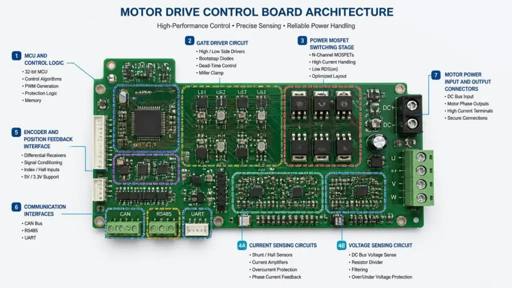
Motor Drive Control Board Architecture and Functional Configuration
Motor drive control boards are not limited to one standard circuit architecture. Their design depends on how the OEM divides motor-control functions, power conversion, feedback acquisition, and external communication.
2.1 Control Logic and Processing Section
The control section processes operating commands and feedback signals to determine motor behavior.
Depending on the application, it may include:
- Microcontrollers or digital signal processors
- Motor-control processing circuits
- Clock and reset circuits
- Memory and configuration components
- PWM signal generation
- Communication interfaces
- Fault detection and status circuits
The processing platform should be selected according to the required control algorithm, processing performance, interface count, operating environment, and firmware requirements.
For custom OEM projects, the processor and peripheral configuration should be defined before PCB layout and manufacturing documentation are finalized. Changes to the processor, pin assignment, or peripheral interface can affect routing, component placement, power distribution, and the overall board design.
2.2 Power-Drive Interface and Switching Section
The power-drive section controls the electrical energy delivered to the motor. Depending on the system architecture, it may include MOSFETs, IGBTs, gate drivers, switching circuits, protection components, and power connections.
Some products integrate the power stage and control logic on one PCB. Others separate them into different boards to address thermal management, electrical isolation, serviceability, or mechanical constraints.
The manufacturing requirements of the power section may include:
- Appropriate copper weight and conductor geometry
- Power and ground distribution
- High-current connection design
- Thermal management provisions
- Component spacing and solder-joint reliability
- Suitable PCB material and stack-up
- Electrical clearance and insulation requirements
These requirements must be evaluated against the actual operating voltage, current, switching frequency, environmental conditions, and applicable product standards.
2.3 Current, Voltage, and Position Feedback
Feedback circuits allow the control system to monitor motor operation and respond to changing operating conditions.
Common feedback inputs include:
- Phase-current sensing
- DC-bus voltage monitoring
- Temperature sensing
- Hall-effect sensor signals
- Encoder signals
- Position and speed feedback
- Fault and protection signals
The accuracy and integrity of feedback signals depend on circuit design, component selection, grounding, routing, noise control, and the physical relationship between power and signal circuits.
OEMs should provide the required sensor types, signal ranges, connector definitions, and interface specifications during the quotation stage. These details help the manufacturing partner understand the board configuration and identify potential assembly or test requirements.
2.4 Communication and External Interfaces
Motor drive control boards may communicate with host controllers, industrial equipment, sensors, or other electronic assemblies.
Common interfaces include:
- CAN and CAN FD
- RS-485
- UART
- SPI and I²C
- PWM and digital I/O
- Analog input and output
- Encoder and Hall sensor connections
- Ethernet or other application-specific interfaces
The interface list should include connector types, pin assignments, electrical levels, isolation requirements, and communication functions. Connector selection also needs to consider cable routing, vibration, installation space, and the expected service environment.
2.5 Integrated and Separate Board Architectures
OEM projects generally use one of three architecture approaches.
| Architecture | Configuration | Main considerations |
|---|---|---|
| Integrated control and power board | Control logic and power-drive circuits share one PCB | Compact design, electrical interaction, thermal distribution, and layout complexity |
| Separate control and power boards | Control and power functions are implemented on different PCBs | Board-to-board connections, isolation, thermal separation, and mechanical integration |
| Multi-board control system | Control, power, sensing, or communication functions use multiple assemblies | System integration, connectors, cable interfaces, assembly coordination, and serviceability |
An integrated design can reduce the number of separate assemblies and interconnections. However, it may increase layout complexity because sensitive control signals and high-power switching circuits share the same board.
A separate-board design can provide more flexibility in thermal and electrical partitioning, but it introduces additional connectors, mechanical interfaces, and assembly considerations.
The most suitable architecture should be determined by the complete OEM product requirements rather than by PCB cost alone.
3. Electrical and Interface Specifications for Custom Motor Drive Control Boards
A clear technical specification is the foundation of accurate quotation, engineering review, and manufacturing preparation. Incomplete electrical information can lead to repeated clarification, incorrect component assumptions, and unexpected changes after prototype production.
3.1 Motor and Operating Requirements
The first step is to identify the motor and its operating conditions.
| Specification | Information to provide |
|---|---|
| Motor type | BLDC, PMSM, brushed DC, stepper, servo, or other type |
| Rated voltage | Normal operating voltage |
| Input voltage range | Minimum and maximum supply voltage |
| Continuous current | Expected continuous operating current |
| Peak current | Maximum current and permitted duration |
| Power rating | Rated and maximum operating power |
| Speed range | Required motor speed range |
| Operating mode | Speed, torque, position, or application-specific control |
| Operating environment | Temperature, humidity, vibration, and installation conditions |
Peak and continuous current should be identified separately. A design that operates at a particular current for a short acceleration period may have different thermal and electrical requirements from one that operates continuously at the same current.
3.2 Power Supply and Protection Requirements
The power supply specification should include the input source, voltage range, polarity, expected transients, and power-distribution requirements.
Relevant protection functions may include:
- Overcurrent protection
- Overvoltage and undervoltage protection
- Short-circuit protection
- Overtemperature protection
- Reverse-polarity protection
- Emergency-stop or enable control
- Fault reporting and recovery functions
The required protection architecture depends on the product’s electrical design and applicable safety requirements. The OEM should identify which protection functions are implemented in hardware, firmware, or external system components.
3.3 Feedback and Communication Requirements
The technical package should identify all feedback and communication interfaces, including signal type, operating range, connector, pin assignment, and isolation requirements.
For example, a motor drive control board using encoder feedback requires different interface considerations from a basic BLDC controller using Hall sensors.
For industrial products, communication requirements may also include protocol selection, termination, isolation, connector placement, and compatibility with the host controller.
3.4 Mechanical and Environmental Requirements
Mechanical requirements influence PCB dimensions, component height, mounting holes, connector positions, and enclosure integration.
OEMs should provide:
- PCB dimensions and thickness
- Maximum component height
- Mounting-hole locations
- Connector orientation and position
- Enclosure and mechanical drawings
- Cooling and airflow conditions
- Vibration and shock requirements
- Operating and storage temperature ranges
Mechanical information is particularly important when the board is installed close to motors, heat sinks, metal enclosures, or moving equipment.
3.5 PCB Stack-Up and Manufacturing Inputs
The PCB stack-up should be selected according to the electrical design, current distribution, signal requirements, mechanical constraints, and manufacturing feasibility.
Typical inputs include:
- Number of layers
- Board thickness
- Copper weight for each layer
- Minimum trace and spacing requirements
- Via structures and hole sizes
- Controlled-impedance requirements, where applicable
- Surface finish
- Solder-mask and legend requirements
- Dimensional and registration tolerances
High-current motor-drive designs may require heavy copper, wider power conductors, suitable via structures, and carefully designed thermal paths. The actual copper weight and layer configuration should be confirmed through electrical and thermal design rather than selected solely by application category.
For more detailed manufacturing considerations, refer to PCBKR’s High Current PCB Manufacturing guide.
4. PCB Design and Manufacturing Requirements for Reliable Motor Drive Control Boards
Motor drive control boards combine switching power circuits with sensitive control and feedback signals. PCB manufacturing quality is therefore important to electrical performance, assembly reliability, and long-term product consistency.
4.1 Copper Distribution and High-Current Paths
Power circuits may carry substantial current during normal operation, acceleration, braking, or transient conditions.
The PCB design should account for:
- Current distribution across copper layers
- Trace width and copper thickness
- Via current capacity
- Connector and terminal design
- Temperature rise
- Power and ground return paths
Copper weight alone does not determine current capacity. Conductor geometry, copper distribution, ambient temperature, airflow, board thickness, and operating duty cycle also influence thermal performance.
For complex high-current designs, manufacturing review should consider the complete copper structure and the intended operating conditions.
4.2 Thermal Management and Component Placement
Power semiconductors, gate drivers, current-sensing components, and power-management devices can generate heat during operation.
Thermal design may involve:
- Copper planes and thermal spreading
- Thermal vias
- Component spacing
- Heat-sink mounting areas
- Airflow paths
- Thermal interface materials
- Separation of high-temperature and temperature-sensitive components
The PCB manufacturer’s role is to manufacture the specified board structure consistently. Thermal performance validation also depends on component selection, PCB layout, enclosure design, cooling arrangements, and the OEM’s operating conditions.
4.3 Switching Noise and Signal Integrity
Fast switching transitions can generate electromagnetic interference and affect nearby control or feedback circuits.
Design measures may include:
- Appropriate power-loop layout
- Controlled switching-current return paths
- Separation of sensitive signals from noisy power circuits
- Grounding strategy
- Decoupling and filtering
- Suitable placement of gate drivers and switching devices
- Isolation where required
For manufacturing, the board supplier should be able to review the supplied design data against applicable fabrication rules and raise manufacturability concerns. Final EMI and EMC performance must be validated in the intended product configuration.
4.4 PCB Materials and Stack-Up Selection
Material selection should consider operating temperature, mechanical requirements, electrical properties, copper configuration, and manufacturing process compatibility.
Common material considerations include:
| Material or construction | Typical consideration |
|---|---|
| Standard FR-4 | General-purpose control boards and moderate electrical requirements |
| High-Tg FR-4 | Applications requiring higher thermal resistance during assembly or operation |
| Heavy-copper PCB | Power sections requiring higher copper cross-section |
| Metal-core PCB | Designs where the thermal path and mechanical structure suit a metal-core construction |
| Multilayer FR-4 | Boards requiring more complex routing, power distribution, or signal separation |
Not every motor drive control board requires high-frequency or advanced HDI materials. Material selection should follow the actual electrical, thermal, mechanical, and cost requirements.
4.5 Advanced PCB Fabrication and Process Control
Advanced fabrication equipment helps manufacturers control critical dimensions and maintain repeatable production processes.
Relevant manufacturing processes include:
- Laser Direct Imaging (LDI) for circuit pattern transfer
- Controlled lamination for multilayer board construction
- Mechanical and laser drilling for different via structures
- Copper plating and pattern control
- Automated Optical Inspection (AOI)
- Electrical testing
- Dimensional and registration inspection
PCBKR’s manufacturing capabilities include SCREEN Ledia LDI equipment, controlled multilayer lamination, laser-drilling processes, and inspection technologies such as AOI and X-ray. The actual process route should be selected according to the board’s layer count, copper structure, hole design, and production requirements.
For advanced circuit structures, PCBKR also has mSAP manufacturing experience with 8/8 µm line/space capability. This is relevant to designs requiring fine circuit features, but it should not be treated as a default requirement for ordinary motor drive control boards.
The manufacturing process should match the design. Unnecessary advanced processes can increase cost without improving the product’s actual performance.
5. Motor Drive Control Board PCBA Assembly Requirements
PCB fabrication is only one part of a complete motor drive control board project. The assembly stage introduces additional requirements involving component sourcing, placement accuracy, soldering quality, inspection, and functional verification.
5.1 Component Procurement and BOM Management
The Bill of Materials defines the components required for the assembly.
Typical components may include:
- Microcontrollers and processors
- MOSFETs or IGBTs
- Gate-driver ICs
- Current and voltage sensors
- Power-management ICs
- Capacitors and resistors
- Inductors and protection components
- Connectors and terminals
- Communication transceivers
- Feedback and interface components
The BOM should identify manufacturer part numbers, approved alternatives, package types, quantities, and special procurement requirements.
For critical power semiconductors and control ICs, component substitutions should not be made without the OEM’s approval. Differences in electrical ratings, package dimensions, thermal characteristics, and switching behavior can affect the final product.
A complete quotation should clearly distinguish customer-supplied components, supplier-procured components, approved alternatives, and components requiring special sourcing.
5.2 SMT and THT Assembly
Motor drive control boards may combine surface-mount and through-hole components.
SMT assembly is commonly used for processors, driver ICs, passive components, and many power devices. THT assembly may be required for connectors, terminals, large components, or parts subject to mechanical stress.
The assembly process should consider:
- Component package and placement requirements
- PCB warpage and thickness
- Solder-paste printing
- Reflow profile
- Through-hole soldering method
- Thermal mass of power components
- Connector alignment
- Inspection access
- Board handling and protection
Large power components and connectors may require particular attention because their mechanical and thermal characteristics differ from those of small signal components.
5.3 Assembly Inspection and Defect Prevention
Inspection methods should be selected according to the component package, assembly complexity, and product risk.
Typical inspection methods include:
| Inspection method | Application |
|---|---|
| 3D AOI | Inspection of component presence, placement, polarity, and visible solder defects |
| X-ray inspection | Examination of hidden solder joints and selected complex packages |
| Visual inspection | Review of assembly condition, connector orientation, and workmanship |
| Electrical testing | Verification of specified electrical connections and continuity |
| Functional testing | Verification of defined board functions under agreed test conditions |
No single inspection method can replace a complete quality plan. For example, AOI can detect many visible assembly defects but does not independently prove that a motor drive control board performs correctly under its intended operating load.
6. Testing and Quality Verification for Prototype and Production Builds
A motor drive control board test plan should be defined before production rather than added after the first prototype has been assembled.
The required tests depend on the board architecture, power rating, interfaces, safety requirements, and the customer’s acceptance criteria.
6.1 Bare PCB Electrical Testing
Bare-board electrical testing verifies the manufactured PCB against the specified electrical connection requirements.
Typical checks include:
- Open-circuit testing
- Short-circuit testing
- Continuity verification
- Isolation checks where specified
- Dimensional inspection
- Visual inspection
The exact testing method and acceptance criteria should follow the PCB drawing, fabrication specification, and applicable standards.
6.2 PCBA Inspection and Electrical Checks
After assembly, inspection and electrical checks help identify assembly defects before functional testing.
These may include:
- Component presence and orientation
- Solder-joint inspection
- Polarity verification
- Connector and terminal inspection
- Power and ground continuity
- Selected in-circuit electrical checks
For critical assemblies, the OEM should define the required inspection coverage and acceptance criteria.
6.3 Functional Testing
Functional testing verifies the board’s operation against the agreed test specification.
Depending on the product, test functions may include:
- Power-up and power-sequence verification
- Control processor startup
- Communication interface checks
- PWM output verification
- Sensor input checks
- Fault and protection response
- Motor enable and disable functions
- Selected speed or direction commands
A functional test requires suitable test fixtures, test software, defined input conditions, and acceptance limits.
Motor operation under load may require a dedicated test setup involving the motor, power supply, load equipment, and safety controls. The OEM and manufacturer should agree on whether this test is included in the PCBA production scope or performed during system-level validation.
6.4 Thermal and Application-Level Validation
Thermal testing may be necessary for boards containing high-power switching devices or operating in restricted enclosures.
The test conditions should define:
- Input voltage
- Continuous and peak current
- Operating duration
- Ambient temperature
- Cooling and airflow conditions
- Measurement locations
- Temperature acceptance limits
EMI/EMC, vibration, environmental, and full-system testing may also be required depending on the final application. These tests should be assigned clearly between the board manufacturer, OEM, and system integrator.
6.5 Production Consistency and Traceability
Passing a prototype test does not automatically guarantee consistent mass production.
A production quality plan should address:
- Approved BOM and component revisions
- PCB fabrication revision control
- Assembly process documentation
- First-article or initial-build inspection
- Production inspection records
- Test results and acceptance criteria
- Nonconformance handling
- Engineering change control
- Batch identification and traceability
These controls help reduce the risk of differences between prototype, pilot production, and subsequent manufacturing batches.
7. Motor Drive Control Board Manufacturer Evaluation
Selecting a manufacturer requires evaluating more than the quoted price per board. OEM procurement teams should review the supplier’s PCB fabrication capability, PCBA process, engineering communication, quality controls, and production planning.
7.1 PCB Fabrication Capability
The supplier should be able to manufacture the specified layer count, board thickness, copper weight, hole structure, material, and dimensional tolerances.
For more demanding designs, buyers should request evidence relevant to the actual project, such as:
- Equipment and process capability
- Stack-up review
- Copper and plating process controls
- Hole and via quality inspection
- Registration and dimensional control
- Electrical test capability
- Sample inspection records
A supplier’s general equipment list is not sufficient by itself. The buyer should confirm that the required process can be applied to the specific board design.
7.2 PCBA and Component Sourcing Capability
For turnkey projects, the manufacturer should explain how it manages component procurement, approved substitutions, incoming inspection, SMT/THT assembly, and final inspection.
Procurement teams should clarify:
- Whether the supplier supports turnkey or consigned assembly
- How component authenticity and sourcing are controlled
- How obsolete or unavailable components are handled
- Whether alternative parts require written approval
- Which inspection methods are included
- Whether functional testing is available for the project
The division of responsibility should be documented in the quotation and manufacturing agreement.
7.3 Engineering Communication and DFM Support
A reliable manufacturing partner should be able to identify manufacturing questions before production begins.
Relevant engineering review topics include:
- PCB fabrication-rule compatibility
- Stack-up and copper requirements
- Drill and via structures
- Component package and assembly constraints
- Board dimensions and mechanical interfaces
- BOM completeness
- Test-point accessibility
- Special process requirements
DFM feedback should identify specific issues and proposed actions. It should not be treated as a general statement that a design is manufacturable without reviewing the actual production files.
7.4 Quality Systems and Process Documentation
OEMs should review the supplier’s quality-management arrangements and verify whether relevant certifications apply to the manufacturing site, business scope, and product category.
Useful evidence may include:
- Valid certification documents
- Inspection and test procedures
- Nonconformance management
- Corrective-action processes
- Production records
- Material and component traceability
- Revision and change management
Certification claims should always be verified against the relevant certificate and its scope. A certification held by a company does not automatically mean every product or process is covered by that certification.
7.5 Prototype, Small-Batch, and Mass-Production Support
The supplier should understand the different requirements of prototype builds, engineering validation, pilot production, and mass production.
A suitable manufacturing process should support controlled transitions between these stages.
| Production stage | Main objective | Key supplier responsibility |
|---|---|---|
| Prototype | Verify design and manufacturing feasibility | Fabrication, assembly, initial inspection, and issue feedback |
| Engineering validation | Confirm board operation against defined requirements | Support agreed test conditions and engineering changes |
| Pilot production | Confirm repeatability and production readiness | Process review, material confirmation, and production inspection |
| Mass production | Maintain stable quality and delivery | Process control, traceability, inspection, and change management |
For OEMs, choosing a supplier that can support multiple production stages may simplify communication and reduce the need to transfer manufacturing data between unrelated vendors.
8. Motor Drive Control Board RFQ and Procurement Requirements
A complete RFQ package allows manufacturers to evaluate the project more accurately and reduces unnecessary quotation delays.
8.1 Essential Technical Files
Buyers should prepare the following information where available:
| File or information | Purpose |
|---|---|
| Gerber or ODB++ files | PCB fabrication data |
| PCB stack-up | Layer configuration, copper weight, and board thickness |
| Drill files | Hole and via information |
| BOM | Component part numbers, quantities, and approved alternatives |
| Pick-and-place file | Component coordinates and orientation |
| Assembly drawings | Component placement and assembly instructions |
| Schematic | Circuit reference and engineering clarification |
| PCB fabrication drawing | Dimensions, tolerances, finish, and special requirements |
| Test specification | Electrical and functional acceptance criteria |
| Mechanical drawings | Enclosure, mounting, and connector integration |
For an early-stage project without completed manufacturing files, buyers should provide a product specification, block diagram, preliminary schematic, and mechanical requirements. The manufacturer can then determine which additional information is necessary for a meaningful quotation.
8.2 Commercial and Production Information
The RFQ should also include:
- Prototype quantity
- Expected monthly or annual volume
- Target delivery schedule
- Required production location
- Packaging requirements
- Shipping destination
- Customer-supplied or supplier-procured materials
- Required certifications or standards
- Expected production forecast
- Special quality or traceability requirements
Quantity information is particularly important because prototype and mass-production quotations may involve different setup, material, component procurement, and inspection costs.
8.3 Quotation Comparison Criteria
OEM buyers should compare quotations using the same technical and commercial scope.
| Evaluation item | Points to confirm |
|---|---|
| PCB fabrication | Layer count, thickness, copper weight, material, finish, and tolerances |
| PCBA scope | SMT, THT, component procurement, and assembly coverage |
| Component sourcing | Approved manufacturers, alternatives, and procurement responsibilities |
| Testing | AOI, X-ray, electrical checks, and agreed functional tests |
| Engineering support | DFM review, file clarification, and change handling |
| Delivery | Prototype lead time, production lead time, and shipping terms |
| Quality | Inspection records, traceability, and acceptance criteria |
| Commercial terms | Tooling, NRE, material costs, payment terms, and quotation validity |
The lowest unit price may not represent the lowest total project cost. Missing test coverage, unclear component substitutions, incomplete engineering review, or repeated production changes can create additional expenses later.
9. PCBKR Motor Drive Control Board Manufacturing and PCBA Support
Shenzhen Hongda Circuit Technology Co., Ltd. provides PCB fabrication and PCBA manufacturing services for OEM and electronics projects. For custom motor drive control board programs, manufacturing requirements should be evaluated against the actual design files, electrical specifications, component list, and production volume.
9.1 PCB Fabrication and Process Capabilities
PCBKR’s manufacturing resources include LDI imaging, multilayer lamination, laser-drilling processes, circuit patterning, and automated inspection.
These processes support different PCB manufacturing requirements:
- LDI imaging for circuit pattern definition
- Controlled lamination for multilayer construction
- Laser drilling for applicable microvia structures
- Copper patterning and plating processes
- AOI for circuit inspection
- X-ray inspection for selected internal structures and assembled components
- Electrical testing for PCB connection verification
The appropriate manufacturing route depends on the board’s layer count, copper weight, via design, line/space requirements, and other fabrication specifications.
9.2 Inspection and Verification Resources
PCBKR’s inspection resources include 3D AOI, X-ray inspection, and four-wire Kelvin flying-probe testing. These methods serve different purposes and should be assigned according to the PCB and PCBA inspection plan.
For designs requiring specialized electrical verification, the test scope should be agreed before production. A complete motor-drive functional test may require customer-specific fixtures, software, motors, loads, and operating conditions beyond standard PCB fabrication inspection.
9.3 Custom PCB and PCBA Project Coordination
A motor drive control board project may involve several connected manufacturing activities:
- Review of PCB fabrication files and specifications
- Stack-up and manufacturing feasibility assessment
- Component and BOM review
- PCB fabrication
- Component procurement according to the agreed sourcing scope
- SMT and THT assembly
- Inspection and agreed electrical tests
- Packaging and delivery
The exact service scope should be confirmed for each project. Firmware development, motor-control algorithm design, system-level certification, and complete motor-load validation should not be assumed to be included unless they are explicitly agreed.
9.4 Prototype to Mass-Production Support
OEM projects often change during development. PCB layout, component selection, connector definitions, and test requirements may be revised after initial samples.
Revision control and clear communication are therefore important throughout the manufacturing process.
PCBKR can evaluate prototype, small-batch, and mass-production requirements according to the supplied technical package and confirmed process scope. Buyers should provide their expected production quantities and development schedule so that manufacturing and material arrangements can be assessed appropriately.
9.5 Related PCB Manufacturing Resources
For projects with specific manufacturing requirements, the following PCBKR resources provide additional technical information:
- High Current PCB Manufacturing — high-current conductor and PCB fabrication considerations.
- PCB Manufacturing Capabilities — manufacturing equipment and process information.
- Motor Driver PCB Manufacturing — motor driver PCB manufacturing and procurement considerations.
- Motor Controller PCB for Robotics OEMs — robotics-oriented motor controller PCB requirements.
10. Motor Drive Control Board RFQ Preparation and Project Initiation
A well-prepared RFQ helps align the OEM’s engineering requirements with the manufacturer’s production capabilities.
Before submitting a project, buyers should confirm the following information:
- Motor type and application
- Input voltage and operating range
- Continuous and peak current
- Control method and processing platform
- Power-stage configuration
- Feedback and communication interfaces
- PCB dimensions, layers, and copper requirements
- Component BOM and sourcing scope
- Assembly and inspection requirements
- Functional test conditions
- Prototype quantity and expected production volume
- Target delivery schedule
If some specifications are not finalized, buyers should identify the open items rather than provide assumptions as confirmed requirements. This allows the manufacturer to identify information gaps before quotation and production preparation.
Submit your Motor Drive Control Board project for manufacturing evaluation.
Shenzhen Hongda Circuit Technology Co., Ltd. welcomes OEM inquiries for custom PCB fabrication and PCBA assembly projects.
Email: sales@pcbkr.com
Website: www.pcbkr.com
To support an efficient review, include your Gerber or ODB++ files, BOM, assembly drawings, technical specifications, and expected order quantity where available.
Frequently Asked Questions About Motor Drive Control Boards
What is the difference between a Motor Drive Control Board and a Motor Driver PCB?
A Motor Drive Control Board may include control processing, feedback acquisition, communication, protection, and power-drive interfaces. A Motor Driver PCB generally refers more specifically to the circuitry responsible for switching or regulating power delivered to the motor. Depending on the product architecture, both functions may be integrated on one PCB or implemented on separate boards.
Can a Motor Drive Control Board be customized for different motor types?
Yes. Custom boards can be developed for BLDC, PMSM, brushed DC, stepper, servo, and other motor applications. The processor, power stage, feedback circuits, communication interfaces, and protection functions must be selected according to the motor and system requirements.
What information is required for a Motor Drive Control Board quotation?
The main information includes PCB manufacturing files, BOM, stack-up, assembly drawings, electrical specifications, interface definitions, test requirements, order quantity, and delivery schedule. For early-stage projects, a schematic, block diagram, and preliminary product specification can help begin the technical review.
Should the control circuit and power stage be integrated on one PCB?
The decision depends on electrical isolation, thermal management, board dimensions, mechanical integration, serviceability, and overall product cost. Integrated designs can reduce interconnections, while separate boards can provide more flexibility in power and control partitioning. The OEM should evaluate the complete system requirements before freezing the architecture.
What testing is required before shipment?
Testing may include bare-board electrical testing, AOI, X-ray inspection, PCBA electrical checks, and agreed functional tests. The required coverage depends on the product design and customer acceptance criteria. Motor-load, thermal, EMI/EMC, and system-level validation should be specifically defined and assigned to the responsible party.
About Author
David Chen LinkedIn Profile
David Chen is a Senior RF/PCB Process Engineer at Shenzhen Hongda Circuit Technology Co., Ltd., with over 12 years of experience in high-frequency PCB fabrication, impedance-controlled stack-up design, and Rogers/PTFE laminate processing. He also boasts an extensive professional background in PCBA manufacturing, PCBA testing, and PCBA optimization, with specialized expertise in high-precision PCBA fault analysis and rigorous PCBA reliability testing. The author has worked with high-layer-count server PCB fabrication, ultra-low-loss backplane stackups, and thermo-mechanical reliability optimization for AI infrastructure projects involving 112G and 224G PAM4 architectures. Skilled in complex circuit design and cutting-edge advanced PCB manufacturing processes, he delivers solutions that elevate product durability and performance across industrial applications. His technical articles focusing on PCBA manufacturing workflows and testing methodologies are widely cited by industry peers and technical platforms, and have gained attention and recognition from industry colleagues.