What Should OEMs Look for in a DIN Rail Module PCBA Manufacturer?
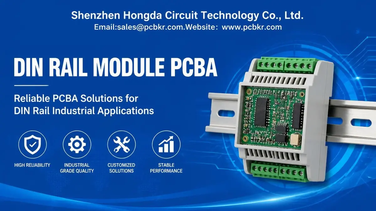
DIN Rail Module PCBA manufacturing requires more than standard PCB assembly. OEMs need reliable PCB fabrication, SMT and through-hole assembly, secure terminal connections, and inspection suited to compact industrial modules. PCBKR provides custom PCB fabrication and PCBA assembly for industrial control, I/O, interface, communication, and power modules, supporting prototype, small-batch, and production requirements. Send your Gerber files and BOM to sales@pcbkr.com for an engineering review and quotation.
1. What Is DIN Rail Module PCBA Manufacturing?
A DIN rail module is an electronic device designed to mount on a standardized DIN rail inside an industrial control cabinet. It may perform signal conditioning, digital or analog I/O, relay switching, power conversion, communication, isolation, or other control functions.
The printed circuit board is only one part of the finished module. Its dimensions, component placement, connectors, terminal blocks, mounting features, and thermal characteristics must work with the intended enclosure and installation environment.
DIN Rail Module PCBA manufacturing therefore involves coordinating several requirements:
- PCB dimensions and mechanical interfaces.
- Electrical connections to field wiring and adjacent modules.
- SMT and through-hole component assembly.
- Power distribution and circuit protection.
- Thermal management within a compact enclosure.
- Inspection and electrical or functional testing.
For OEM buyers, the manufacturing scope should be clearly defined. A PCBA supplier may manufacture the bare PCB and assemble the electronic components, while enclosure molding, DIN rail clips, front panels, mechanical integration, and final product certification may require separate suppliers or separately agreed services.
2. Which Types of DIN Rail Modules Require Custom PCB Assembly?
DIN rail modules are used across industrial automation, building management, instrumentation, power distribution, and machine control. Their circuit designs and assembly requirements vary according to the function of the module.
DIN Rail Digital and Analog I/O Modules
Digital input and output modules connect controllers to field devices such as switches, sensors, relays, and actuators. Analog modules handle signals from devices such as temperature, pressure, and flow sensors.
Their PCB designs may include:
- Input conditioning and filtering circuits.
- Signal conversion and amplification.
- Isolation components.
- Protection against specified electrical disturbances.
- Connector interfaces for field wiring.
- Power regulation for the module electronics.
The number of channels, input ranges, output current, isolation architecture, and connector arrangement should be defined in the design documentation.
DIN Rail Relay and Interface Modules
Relay and interface modules provide switching or signal conversion between control equipment and external circuits.
Assembly considerations include relay footprint accuracy, coil and contact connections, terminal block installation, component orientation, and the electrical separation required by the design.
Where the module switches inductive loads, the circuit may also require appropriately selected suppression or protection components. These should be specified according to the actual load and operating conditions rather than added as generic design assumptions.
DIN Rail Signal Conditioning and Isolation Modules
Signal conditioning modules adapt electrical signals for use by controllers, measurement systems, or other industrial equipment.
Typical circuit functions include:
- Voltage and current signal conversion.
- Analog filtering and amplification.
- Sensor interface conditioning.
- Galvanic isolation.
- Input and output protection.
PCB layout must account for the signal paths, power domains, grounding strategy, component spacing, and isolation requirements specified for the application.
DIN Rail Communication and Gateway Modules
Communication modules may provide interfaces such as RS-485, CAN, Ethernet, or other wired communication standards.
Their PCB assembly may involve communication ICs, isolation devices, protection components, connectors, and controlled-impedance routing where required by the interface design.
For higher-speed or more demanding signal paths, stack-up and routing should be reviewed against the actual electrical requirements. A suitable reference is PCBKR’s High-Speed PCB manufacturing information.
DIN Rail Power Supply and Power Interface Modules
Power modules convert, regulate, distribute, or monitor electrical power within industrial systems.
Depending on the design, they may contain switching devices, transformers or inductors, power management ICs, protection components, and high-current connectors.
The PCB construction and assembly process must reflect the required operating voltage, current, temperature rise, insulation, and thermal conditions. PCBKR’s Power Electronics PCBA manufacturing provides related information about power-oriented assembly requirements.
3. What PCB Design Requirements Matter in DIN Rail Modules?
A DIN rail module often has limited internal space. PCB design decisions must therefore consider the enclosure, connector arrangement, electrical requirements, and manufacturing process together.
PCB Dimensions and Enclosure Compatibility
The PCB outline should be reviewed against the selected enclosure before fabrication. DIN rail housings may use internal PCB guides, mounting slots, support points, or dedicated terminal interfaces.
Important details include:
- Finished PCB length, width, and thickness.
- Board-edge clearances and insertion areas.
- Mounting-hole locations and tolerances.
- Connector height and orientation.
- Component clearance from enclosure walls.
- Access to front-panel indicators, switches, and interfaces.
A PCB that meets its electrical specifications may still be unsuitable if it cannot fit into the intended housing or if its connectors do not align with the enclosure openings.
OEMs should provide the enclosure drawing or mechanical reference during the engineering review. This allows the PCB outline, mounting features, and component placement to be checked before production.
PCB Layer Count, Material, and Copper Construction
Layer count and laminate selection should follow the circuit’s routing density, electrical performance, current requirements, and operating environment.
| Design factor | Common considerations |
|---|---|
| PCB material | Standard FR-4 or a specified higher-temperature laminate |
| Layer count | Single-sided, double-sided, or multilayer according to routing needs |
| Board thickness | Selected to match enclosure space, mechanical support, and connector requirements |
| Copper thickness | Based on current, conductor geometry, and allowable temperature rise |
| Surface finish | Selected according to component, soldering, and product requirements |
| Impedance control | Required where specified for communication or high-speed signal paths |
These are design-dependent selections, not universal DIN rail module specifications. The final construction should be confirmed using the PCB fabrication data and the customer’s electrical and mechanical requirements.
Component Placement and Connector Accessibility
Component placement must account for both manufacturing access and the final module layout.
For example, terminal blocks may need to face the front or side of the enclosure to allow field wiring. LEDs and status indicators may need to align with front-panel windows. Tall components must not interfere with enclosure covers or adjacent PCB structures.
The design review should consider:
- Connector pitch and orientation.
- Component height and enclosure clearance.
- Cable entry and wiring access.
- Test-point accessibility.
- Separation between power and signal sections.
- Soldering and inspection access.
These checks can prevent avoidable mechanical interference and assembly rework.
4. How Should Terminal Blocks and Connectors Be Assembled?
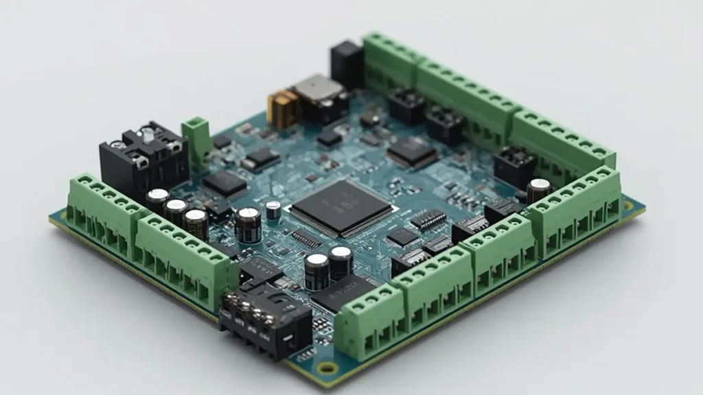
Proper terminal block and connector assembly is essential for reliable electrical connections, mechanical stability, and compatibility with DIN rail module enclosures.
Terminal blocks and connectors are critical interfaces between the PCB and the outside electrical system. Their selection and assembly affect electrical performance, mechanical strength, wiring access, and maintenance.
Fixed and Pluggable PCB Terminal Blocks
Fixed terminal blocks are permanently mounted to the PCB. Pluggable terminal systems use a removable mating connector, allowing field wiring to be disconnected without removing the entire PCB assembly.
The choice depends on:
- Required current and voltage ratings.
- Number of connection positions.
- Wire size and termination method.
- Connector pitch and available space.
- Required insertion and removal cycles.
- Maintenance and replacement requirements.
The selected connector must match the PCB footprint and the mechanical layout of the enclosure. Buyers should provide the exact manufacturer part number or approved connector specification wherever possible.
SMT and Through-Hole Connector Assembly
SMT components are suitable for many compact electronic circuits, but industrial connectors and terminal blocks often use through-hole mounting because of their mechanical structure and connection requirements.
A DIN rail module PCBA may therefore combine:
- SMT resistors, capacitors, ICs, and protection components.
- Through-hole terminal blocks and connectors.
- Relays and other mechanically demanding components.
- Mixed-technology assembly processes.
The assembly sequence and soldering method depend on the component design, PCB layout, soldering requirements, and customer specifications.
Solder Joint and Mechanical Reliability
Terminal blocks may experience wire insertion forces, cable handling, vibration, and repeated connection cycles. These loads can place stress on connector pins and solder joints.
The PCB design should provide suitable pad geometry, hole dimensions, copper connections, and mechanical support. During assembly, solder coverage and joint quality should be inspected according to the agreed acceptance criteria.
Where a connector has substantial mechanical loading, the OEM should identify the expected load conditions and any additional retention or support features in the design documentation.
5. How Can Thermal Management and Electrical Isolation Be Addressed?
DIN rail modules are often installed close to other electronic devices inside control cabinets. Their thermal and electrical design must account for the actual installation environment.
Thermal Management in Compact Enclosures
A compact enclosure restricts the available space for heat dissipation. Heat-producing components may include power semiconductors, regulators, resistors, relays, and communication devices.
Potential PCB-level thermal measures include:
- Appropriate copper area for heat spreading.
- Thermal vias where suitable for the design.
- Component spacing based on expected temperature rise.
- Copper planes designed for power and thermal requirements.
- Placement of heat-producing components with enclosure constraints in mind.
Thermal performance also depends on the enclosure material, ventilation, mounting orientation, surrounding modules, cabinet temperature, and actual operating load.
The DIN rail itself should not automatically be treated as a heat sink. Any heat transfer through the enclosure or mounting structure needs to be evaluated for the specific mechanical design.
For projects with defined temperature limits, OEMs should provide the operating temperature range, power dissipation, duty cycle, cooling arrangement, and required test conditions.
Creepage, Clearance, and Electrical Isolation
Modules connected to different voltage domains may require electrical separation between circuits.
Relevant design considerations include:
- Required working and transient voltages.
- Creepage and clearance distances.
- PCB material and applicable insulation requirements.
- Slots or routing features where specified.
- Isolation component ratings.
- Contamination and environmental conditions.
Creepage and clearance requirements cannot be selected from a generic DIN rail module template. They depend on the applicable product standard, voltage conditions, pollution degree, material characteristics, and other design factors.
The OEM should specify the relevant safety standard and required insulation performance before PCB fabrication.
Protection Against Electrical Disturbances
Industrial modules may be exposed to electrical transients, ESD, switching disturbances, and noise from nearby equipment.
Depending on the application, the circuit may include TVS diodes, filtering components, fuses, surge protection devices, or other protection circuits.
The protection strategy should be reviewed against the actual interface, voltage level, wiring arrangement, and required immunity tests. Component presence alone does not demonstrate compliance with an EMC or safety requirement.
6. What Manufacturing Processes Are Used for DIN Rail Module PCBA?
The manufacturing process depends on the PCB construction and the components listed in the approved BOM.
PCB Fabrication
The bare PCB is manufactured according to the released Gerber or ODB++ data, stack-up, material, copper, surface finish, and dimensional requirements.
The fabrication review should confirm:
- Layer count and stack-up.
- Finished board thickness.
- Copper requirements.
- Drill and finished-hole dimensions.
- PCB outline and mechanical tolerances.
- Surface finish and solder mask.
- Electrical test requirements.
Any controlled-impedance, special material, or advanced via requirements should be clearly identified in the manufacturing data.
SMT Component Assembly
SMT assembly typically involves solder paste application, component placement, and reflow soldering.
For DIN rail modules, particular attention may be needed for fine-pitch ICs, power components, polarity-sensitive devices, and components positioned close to terminal connectors or enclosure boundaries.
The assembly data should include an approved BOM, centroid file, and assembly drawing. Any discrepancies between these files should be resolved before production.
Through-Hole Assembly
Through-hole components may include terminal blocks, connectors, relays, and other parts requiring mechanical attachment.
The process may involve selective soldering, wave soldering, or manual soldering, depending on the PCB design and component arrangement.
The chosen process must be suitable for the component construction and should achieve the agreed soldering and workmanship requirements.
Mixed-Technology Assembly
Many DIN rail modules combine SMT and THT components. Mixed-technology assembly requires coordination between placement, soldering sequence, component clearance, and inspection.
The OEM should identify special assembly requirements, including connector orientation, polarity, soldering restrictions, and any components that must be installed after a particular process stage.
7. What Inspection and Testing Should a DIN Rail Module PCBA Receive?
Inspection and testing should be defined according to the module’s function, component packages, electrical risks, and customer acceptance requirements.
| Inspection or test | Purpose | Application considerations |
|---|---|---|
| Visual inspection | Checks visible assembly workmanship | Component orientation, connector installation, and visible solder defects |
| 3D AOI | Inspects visible component and solder features | Component presence, placement, polarity, and inspectable solder joints |
| X-ray inspection | Examines concealed solder connections | Applicable BGA, bottom-terminated, or other hidden joints |
| Electrical continuity test | Checks specified electrical connections | Open circuits and short circuits within the test coverage |
| Flying probe test | Performs electrical testing without a dedicated fixture | Suitable where the PCB design and test data support the method |
| Functional test | Checks specified circuit operation | Requires defined procedures, fixtures, equipment, and pass/fail limits |
AOI and X-ray Inspection
Automated optical inspection helps identify visible component placement and soldering issues. X-ray inspection is useful for examining concealed solder connections that cannot be assessed through ordinary visual inspection.
Neither method replaces all other tests. The inspection plan should reflect the actual component packages and the risks associated with the assembly.
Electrical Testing
Electrical testing may be used to check continuity, shorts, and other specified electrical characteristics.
PCBKR can provide flying probe and four-wire Kelvin testing options where appropriate to the PCB design and agreed test scope. The required test coverage should be confirmed from the circuit design and manufacturing data.
Functional Testing of I/O and Communication Modules
Functional testing is especially important when the PCBA contains active control, signal conversion, communication, or power circuits.
Depending on the module, a customer-defined test procedure may verify:
- Power input and regulated output voltages.
- Digital input and output operation.
- Analog input and output response.
- Relay switching.
- Communication interface operation.
- Specified protection or monitoring functions.
The test method should identify the input conditions, expected outputs, operating limits, and pass/fail criteria.
If a module must operate with other modules through a shared bus or backplane, that system-level compatibility test should be defined separately. Testing one PCBA does not automatically verify the complete multi-module system.
8. What Should OEMs Prepare Before Requesting a DIN Rail Module PCBA Quotation?
An accurate quotation depends on complete manufacturing data and a clear definition of the supplier’s responsibilities.
Required PCB Fabrication Files
| File or specification | Why it is needed |
|---|---|
| Gerber or ODB++ | Defines PCB copper, solder mask, legend, and other fabrication layers |
| NC drill data | Defines drilled holes and tool information |
| PCB stack-up | Specifies layer arrangement and dielectric construction |
| PCB outline drawing | Defines dimensions, cutouts, and mechanical features |
| Fabrication notes | Specifies material, copper, thickness, finish, and tolerances |
Required PCBA Assembly Files
| File or specification | Why it is needed |
|---|---|
| BOM | Identifies components and manufacturer part numbers |
| Pick-and-place file | Provides SMT component coordinates and orientation |
| Assembly drawing | Shows component locations and special assembly instructions |
| Approved substitutions | Defines whether alternative parts may be used |
| Test procedure | Defines the required electrical and functional verification |
Mechanical and Application Information
For DIN rail modules, PCB files alone may not provide enough information to assess assembly compatibility.
Where available, also provide:
- DIN rail enclosure drawing or model.
- PCB mounting and support details.
- Terminal block and connector specifications.
- Maximum component height.
- Operating temperature range.
- Installation orientation.
- Required electrical isolation and protection conditions.
Commercial Information
To support a useful quotation, include:
- Prototype quantity.
- Expected repeat-order quantity or annual demand.
- Required delivery schedule.
- Component sourcing scope.
- Customer-supplied component details, if applicable.
- Inspection and test requirements.
- Packaging and shipping destination.
Buyers should distinguish between consigned, partial-turnkey, and full-turnkey PCBA requirements. These service models involve different sourcing responsibilities and should be clearly stated in the RFQ.
9. How Should OEMs Select a DIN Rail Module PCBA Manufacturer?
A suitable manufacturing partner should be able to review the technical files, identify manufacturing risks, confirm the assembly scope, and provide a production process aligned with the product requirements.
The following points are useful when evaluating potential suppliers.
| Evaluation area | What buyers should confirm |
|---|---|
| PCB fabrication | Whether the supplier can meet the specified material, layers, copper, thickness, and finish |
| SMT and THT assembly | Whether the supplier can handle the actual component packages and connector types |
| Mixed-technology process | Whether the assembly sequence suits the PCB and BOM |
| Terminal block assembly | Whether connector orientation, hole dimensions, and soldering requirements can be met |
| Inspection | Whether AOI, X-ray, and electrical testing are appropriate for the design |
| Functional testing | Whether the supplier can follow the customer’s defined procedure |
| Component sourcing | Whether approved manufacturer part numbers and substitution controls are followed |
| Production support | Whether prototype, small-batch, and repeat production requirements can be reviewed |
| Quality documentation | Whether inspection records and agreed production documentation can be supplied |
Do not evaluate a supplier only by the equipment listed on its website. Ask how the proposed process applies to your actual PCB, connectors, component packages, and test requirements.
For broader industrial control applications, see PCBKR’s Intelligent Industrial Control PCB manufacturing information. For other OEM control-board requirements, refer to Embedded Control Board OEM and PCBA services.
10. Why Work with PCBKR for DIN Rail Module PCBA Manufacturing?
Shenzhen Hongda Circuit Technology Co., Ltd. (PCBKR) provides PCB fabrication and PCBA assembly services for OEM electronic products. For DIN rail module projects, the manufacturing scope can be reviewed according to the PCB design, component requirements, connector arrangement, production quantity, and customer inspection specifications.
Relevant manufacturing capabilities include:
- PCB fabrication: Manufacturing based on customer Gerber or ODB++ data and approved PCB specifications.
- SMT assembly: Surface-mount component placement and reflow soldering.
- THT assembly: Through-hole component and connector assembly according to the project requirements.
- Mixed-technology PCBA: SMT and THT processes for boards combining compact electronic circuits and industrial connectors.
- Inspection: 3D AOI and X-ray inspection where appropriate to the assembly.
- Electrical testing: Flying probe and four-wire Kelvin testing where applicable.
- Production support: Project review for prototype, small-batch, and production orders.
The final manufacturing and testing scope is confirmed against the actual design files, BOM, assembly drawings, and customer requirements. Enclosure manufacturing, DIN rail mechanical integration, firmware development, and complete finished-module delivery should be specified separately if required.
Request a DIN Rail Module PCBA Quotation
If your company is developing a DIN rail I/O module, relay interface, signal conditioning module, communication module, or industrial power module, PCBKR can review the PCB fabrication and PCBA assembly requirements.
For an initial engineering review, send:
- Gerber or ODB++ files.
- BOM with manufacturer part numbers.
- Pick-and-place file and assembly drawings.
- PCB stack-up and mechanical outline.
- Target quantity and delivery schedule.
- Required inspection and functional test specifications.
Email: sales@pcbkr.com
Website: https://www.pcbkr.com
Contact PCBKR to discuss your DIN Rail Module PCBA manufacturing requirements and request a project-specific quotation.
11. Frequently Asked Questions About DIN Rail Module PCBA Suppliers
What files should I send to a DIN rail module PCBA manufacturer for a quotation?
Provide Gerber or ODB++ files, NC drill data, PCB stack-up, BOM, pick-and-place file, and assembly drawings. For DIN rail modules, enclosure drawings, connector specifications, mounting details, and required functional tests are also useful. Include the target quantity and delivery schedule so the supplier can evaluate the complete manufacturing scope.
Can a PCBA manufacturer handle both SMT components and through-hole terminal blocks?
Yes, a manufacturer with suitable SMT and THT assembly processes can handle mixed-technology boards. The actual process depends on the terminal block construction, PCB hole and pad design, component arrangement, and soldering requirements. Confirm the connector specifications and assembly drawings before production.
How do I ensure the PCB fits the DIN rail enclosure?
Provide the enclosure drawing or mechanical model together with the PCB outline and assembly information. The design review should check PCB dimensions, thickness, mounting features, component height, connector orientation, and clearance from enclosure walls. The final mechanical fit should be verified against the actual enclosure design.
Can DIN rail module PCBA suppliers support prototype, small-batch, and mass production?
Many PCBA suppliers support more than one production volume, but the available process, sourcing arrangements, pricing, and lead time may differ by order size. Ask the supplier to review the prototype quantity, expected production volume, BOM availability, and test requirements before confirming the production plan.
What inspection and functional tests should I require from a DIN rail PCBA supplier?
The test plan depends on the module’s function and design. Typical options include visual inspection, AOI, X-ray for suitable hidden solder joints, electrical continuity testing, and customer-defined functional tests. I/O, relay, communication, and power modules may require different test procedures. Define the required coverage and acceptance limits before quotation.
About Author
David Chen LinkedIn Profile
David Chen is a Senior RF/PCB Process Engineer at Shenzhen Hongda Circuit Technology Co., Ltd., with over 12 years of experience in high-frequency PCB fabrication, impedance-controlled stack-up design, and Rogers/PTFE laminate processing. He also boasts an extensive professional background in PCBA manufacturing, PCBA testing, and PCBA optimization, with specialized expertise in high-precision PCBA fault analysis and rigorous PCBA reliability testing. The author has worked with high-layer-count server PCB fabrication, ultra-low-loss backplane stackups, and thermo-mechanical reliability optimization for AI infrastructure projects involving 112G and 224G PAM4 architectures. Skilled in complex circuit design and cutting-edge advanced PCB manufacturing processes, he delivers solutions that elevate product durability and performance across industrial applications. His technical articles focusing on PCBA manufacturing workflows and testing methodologies are widely cited by industry peers and technical platforms, and have gained attention and recognition from industry colleagues.